
UNI_WATERSOFTENER_500 - Other kitchen appliances Uniprodo - Free user manual and instructions
Find the device manual for free UNI_WATERSOFTENER_500 Uniprodo in PDF.

| Product type | Water softener |
| Brand | Uniprodo |
| Model | UNI_WATERSOFTENER_500 |
| Rated voltage | 230 V / 50 Hz |
| Resin tank capacity | 5 L |
| Resin type | 0713 |
| Flow rate | 1,7 - 3,1 m³/h |
| Working pressure | 1,5 - 5,0 bar |
| Inlet/outlet diameter | 1" |
| Drain port diameter | ∅12 mm |
| Dimensions (L x W x H) | 500 x 222 x 505 mm |
| Weight (without salt) | 10,9 kg |
| Ambient temperature | 1 - 30 °C |
| Main functions | Water softening, automatic regeneration (backwash, brine, fast rinse, fill) |
| Valve type | ASD2 (default) |
| Operating mode | Intelligent flow meter start delay (A-03 by default) |
| Maintenance and cleaning | Clean with a soft cloth; do not immerse in water; use mild detergents |
| Safety | Automatic shutdown in case of power failure (settings lost after 48 h); overpressure protection (max 5 bar) |
| Spare parts and repairability | Resin, seals, bypass valve, flow meter, etc. available on request |
| General information | User manual downloadable; CE compliance; domestic and professional use (restaurants, hotels) |
Frequently Asked Questions - UNI_WATERSOFTENER_500 Uniprodo
User questions about UNI_WATERSOFTENER_500 Uniprodo
0 question about this device. Answer the ones you know or ask your own.
Ask a new question about this device
Download the instructions for your Other kitchen appliances in PDF format for free! Find your manual UNI_WATERSOFTENER_500 - Uniprodo and take your electronic device back in hand. On this page are published all the documents necessary for the use of your device. UNI_WATERSOFTENER_500 by Uniprodo.
USER MANUAL UNI_WATERSOFTENER_500 Uniprodo
Tong Suiyutu, Duihun, Huaizhui, Linjiao, and Tan Fai
(Average Water Used)
Average Water Used
5.00 m ^3
| Parameter description | Parameter value | |
| Product name Water softener | ||
| Model UNL | WATERSOFTENER_2500A | UNL WATERSOFTENER_1000A |
| Rated voltage [V-]/ Frequency [Hz] | 230/30 | |
| Resin tank capacity [l] 25.12 | ||
| Resin tank type 1035 1017 | ||
| Flow speed [m3/h] 1.4 2.7 1.4 - 2.6 | ||
| Operation pressure [bar] | 1.5 - 5.0 | |
| Inlet/oulet diameter [°] | 1 | |
| Drain diameter [mm] | ∅12 | |
| Dimensions [mm] 480x300x1120 510x290x660 | ||
| Weight [kg] (without set) | 36.5 21 | |
| Ambient temperature [°C] | 1-39 | |
| Product name Water softener | ||
| Model UNL | WATERSOFTENER_1300 | UNL WATERSOFTENER_750 |
| Rated voltage [V-]/ Frequency [Hz] | 230/30 | |
| Resin tank capacity [l] 19.5.5 | ||
| Resin tank type 0735 0717 | ||
| Flow speed [m3/h] 1.6 2.9 1.4 - 2.8 | ||
| Operation pressure [bar] | 1.5 - 5.0 | |
| Inlet/oulet diameter [°] | 1 | |
| Drain diameter [mm] | ∅12 | |
| Dimensions [mm] 510x250x1070 510x220x595 | ||
| Weight [kg] (without set) | 24.3 14 | |
| Ambient temperature [°C] | 1-39 | |
| Product name Water softener | ||
| Model UNL | WATERSOFTENER_500 | UNL WATERSOFTENER_3500 |
| Rated voltage [V-]/ Frequency [Hz] | 230/30 | |
| Resin tank capacity [l] 5 | 33 | |
| Resin tank type 0713 1324 | ||
| Flow speed [m3/h] 1.7 - 3.1 2.1 - 4.0 | ||
12 13EN
| Operation pressure [bar] | 1.3-5.0 | |
| Inlet/oulet diameter [°] | 1 | |
| Drain diameter [mm] | Ø12 | |
| Dimensions [mm] | 500x222x305 | 530x360x810 |
| Weight [kg] (without sat.) | 10.9 | 41.3 |
| Ambient temperature [°C] | 1-39 | |
| Product name Water softener | ||
| Model | UNL_WS_10008 | |
| Rated voltage [V/-] / Frequency [Hz] | 230/30 | |
| Resin tank capacity [l] | 12 | |
| Resin tank type | 1017 | |
| Flow speed [m3/h] | 0,1-2,61 | |
| Operation pressure [bar] | 1,5-4,5 | |
| Inlet/oulet diameter [°] | 3/4" / 1" | |
| Drain diameter [mm] | Ø 14 | |
| Dimensions [mm] | 345x350x655 | |
| Weight [kg] (without sat.) | 22 | |
| Ambient temperature [°C] | 5-38 | |
- GENERAL DESCRIPTION
The user manual is designed to assist in the safe and trouble-free use of the device. The product is designed and manufactured in accordance with strict technical guidelines, using state-of-the-art technologies and components. Additionally, it is produced in compliance with the most stringent quality standards.
DO NOT USE THE DEVICE UNLESS YOU HAVE THOROUGHLY READ AND UNDERSTOOD THIS USER MANUAL.
To increase the product life of the device and to ensure trouble-free operation, use it in accordance with this user manual and regularly perform maintenance tasks. The technical data and specifications in this user manual are up to date. The manufacturer reserves the right to make changes associated with quality improvement. The device is designed to reduce noise emission risks to a minimum, taking into account technological progress and noise reduction opportunities.
LEGEND
| The product satisfies the relevant safety standards. |
| Read instructions before use. |
| The product must be recycled. |
| WARNING: or CAUTION! or REMEMBER! Applicable to the given situation (general warning sign). |
| ATTENTION: Electric shock warning! |
07.09.2023
EN
PLEASE NOTE! Drawings in this manual are for illustration purposes only and in some details may differ from the actual product.
The original operation manual is written in German. Other language versions are translations from the German.
2. USAGE SAFETY
ATTENTION! Read all safety warnings and all instructions. Failure to follow the warnings and instructions may result in serious injury or even death.
The terms "device" or "product" are used in the warnings and instructions to refer to
2.1. ELECTRICAL SAFETY
a) The plug must fit the socket. Do not modify the plug in any way. Using original plugs and matching sockets reduces the risk of electric shock.
b) Avoid touching earthed elements such as pipes, heaters, boilers and refrigerators. There is an increased risk of electric shock if the earthed device is exposed to rain, comes into direct contact with a wet surface or is operating in a damp environment. Water getting into the device increases the risk of damage to the device and of electric shock.
c) Do not touch the device with wet or damp hands.
d) Use the cable only for its designated use. Never use it to carry the device or to pull the plug out of a socket. Keep the cable away from heat sources, oil, sharp edges or moving parts. Damaged or tangled cables increase the risk of electric shock.
e) If using the device in a clamp environment cannot be avoided, a residual current device (RCD) should be applied. The use of an RCD reduces the risk of electric shock.
Do not use the device if the power cord is damaged or shows obvious signs of wear. A damaged power cord should be replaced by a qualified electrician or the manufacturer's service centre.
g1 To avoid electric shock, do not immerse the cord, plug or device in water or other liquids. Do not use the device on wet surfaces.
h) The power cord connected to the appliance must be properly grounded and correspond to the technical details on the product label.
2.2.SAFETY IN THE WORKPLACE
a) Make sure the workplace is clean and well lit. A messy or poorly lit workplace may lead to accidents. Try to think ahead, observe what is going on and use common sense when working with the device.
b) Do not use the device in a potentially explosive environment, for example in the presence of flammable liquids, gases or dust. The device generates sparks which may ignite dust or fumes.
c) If you discover damage or irregular operation, immediately switch the device off and report it to a supervisor without delay.
d) If there are any doubts as to the correct operation of the device, contact the manufacturer's support service.
e) Only the manufacturer's service point may repair the device. Do not attempt any repairs independently!
In case of fire, use a powder or carbon dioxide (CO₂) fire extinguisher (one intended for use on live electrical devices) to put it out.
g1 Regularly inspect the condition of the safety labels. If the labels are illegible, they must be replaced.
h) Please keep this manual available for future reference. If this device is passed on to a third party, the manual must be passed on with it.
1) Keep packaging elements and small assembly parts in a place not available to children.
J) Keep the device away from children and animals.
k) If this device is used together with another equipment, the remaining instructions for use shall also be followed.
REMEMBER! When using the device, protect children and other bystanders.
2.3. PERSONAL SAFETY
a) Do not use the device when tired, ill or under the influence of alcohol, narcotics or medication which can significantly impair the ability to operate the device.
b) The device is not designed to be handled by persons (including children) with limited mental and sensory functions or persons lacking relevant experience and/or knowledge unless they are supervised by a person responsible for their safety or they have received instruction on how to operate the device.
c) When working with the device, use common sense and stay alert. Temporary loss of concentration while using the device may lead to serious injuries.
d) The device is not a toy. Children must be supervised to ensure that they do not play with the device.
2.4. SAFE DEVICE USE
a) Disconnect the device from the power supply before commencement of adjustment, cleaning and maintenance. Such a preventive measure reduces the risk of accidental activation.
b) When not in use, store in a safe place, away from children and people not familiar with the device who have not read the user manual. The device may pose a hazard in the hands of inexperienced users.
c) Keep the device in perfect technical condition. If damage is discovered, hand over the device for repair before use.
d) Keep the device out of the reach of children.
e) Device repair or maintenance should be carried out by qualified persons, only using original spare parts. This will ensure safe use.
f) To ensure the operational integrity of the device, do not remove factory-fitted guards and do not loosen any screws.
g) When transporting and handling the device between the warehouse and the destination, observe the occupational health and safety principles for manual transport operations which apply in the country where the device will be used.
h) Do not move, adjust or rotate the device in the course of work.
I) Clean the device regularly to prevent stubborn grime from accumulating.
j) The device is not a toy. Cleaning and maintenance may not be carried out by children without supervision by an adult person.
k) It is forbidden to interfere with the structure of the device. In order to change its parameters or construction.
I) Keep the device away from sources of fire and heat.
m) During transport, installation and use of this product, do not dit the device as this may lead to a damage.
n) During regeneration, the water supplied to the device will NOT be softened. It is NOT recommended to use water during regeneration because it will have a negative effect on the regeneration result.
14 15EN EN
b) If the device has been turned off for a long time, activate the regeneration cycle and unscrew the tap a few minutes before starting normal operation of the device:
p) Disconnection from the power supply may change the settings of the device. After each power break, check the device clock and other parameters.
q) If the water hardness changes significantly, it should be adjusted in the user settings menu.
r) Hot water can cause serious damages to the device. When using a boiler/water heater, make sure that the total length of pipes connecting the softener and the boiler/water heater is at least 3 meters; if the required pipe length cannot be met, it is recommended to install a check valve between the filter and the boiler/water heater.
s) The inlet water pressure must fluctuate between 1.5 and 5 bar. Negative water pressure is not allowed.
t) It is forbidden to use chemicals on the inlet and outlet of the device.
u) Do not allow the device to freeze.
v) Provide a water drain in the floor near the device in the case of leakiness.

A. Overflow pipe
B. Floor drain
w) Do not subject the product to mechanical pressure. x) Do not expose the device to direct sunlight.
y) Use only regenerating salt in tablets.
2) Use only teflon tape to seal pipes and connections.
sa) Connect the device to the power supply only after all operations related to the water installation has been completed.
bb) Do not move the device using hoses, valves, connections and other sensitive elements of the controller.
ATTENTION! Despite the safe design of the device and its protective features, and despite the use of additional elements protecting the operator, there is still a slight risk of accident or injury when using the device. Stay alert and use common sense when using the device.
- USE GUIDELINES
The device is intended to soften water in water-supply systems. The product is intended for private households as well as for businesses such as restaurants, bars or hotels. The user is liable for any damage resulting from unintended use of the device.
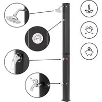
3.1. DEVICE DESCRIPTION Water softener pipes
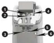
- Drain
- Flow meter
- inlet
- Brine pipe
- Outlet
3.2. DEVICE USE
CAUTION: The controllers are driven by an electrical circuit. Some of the programmed parameters will be lost due to power break which will last longer than 48 hours and then the device will perform the regeneration process at the wrong time.
After each power break, check the device clock.
Operation cycle:
• IN SERV.: Water treatment. Water flows in through the controller, flows through a deposit (resin) and flows out to the water-supply system.
- BACKWASH: Backwash - Water rinses and scarifies the deposit and then goes to the sewage system. This step is necessary before regeneration.
- BRINE AND SLOW RINSE: Regeneration - Brining and slow rinsing. The flow of water through a control head causes sucking the brine in, which regenerates the softening capacity of the deposit. During the regeneration, water is drained away to the sewage system. After all the brine has been sucked in, the lon-exchange deposit is slowly rinsed with water.
- FAST RINSE: Fast rinsing of the deposit out of brine residues. After flowing through the deposit, the water is directed to the sewage system.
• REFILLING: Pouring water into the salt tank to prepare the brine solution for the next regeneration.
During the regeneration of the deposit, it is not possible to uptake raw water. The device cuts off the water supply during regeneration
Usage
The device should be installed and prepared for use by a qualified person. No additional steps are necessary as long as the power supply is maintained all the time and the sufficient amount of salt is in the brine tank. Three water-supply ports (the inlet, outlet, drain) and the power supply are required for installation.
First start
CAUTION: Deposit regeneration is required before the first use. 1. Set the controller to backwash mode, then slowly
open the water inlet valve to approximately 1%. Water will flow into the resin tank (if the valve is opened too quickly or too much, the resin may be rinsed). When all air is removed from the tank (water begins to flow evenly from the drain), fully open the main supply valve.
-
Drain the water until clear will flow out.
-
Shut off the water supply and leave the device for
about five minutes to get rid of the air in the tank
-
Manually start the regeneration cycle after filling the resin tank in order to pour water into the brine tank.
-
Fill the brine tank with salt. The salt level should be higher than the water level.
It is recommended to install a bypass system to ensure water supply in special cases, such as softener breakdown, maintenance, etc.
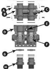
Bypass valve (bypass)
The bypass valve is used when the device needs repair or maintenance. It allows water supply during these operations.
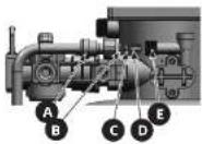
Bypass valve (bypass)
Bypass posit
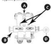
A. Rowmeter port
B. Bypass piston rod
C. Inlet and outlet marks
D. Water hardness control knob
Position for softened water supply
E. Bypass piston
F. Inlet valve nut
Bypass valve installation instructions for models:
UNI WATERSOFTENER 1500,
UNI WATERSOFTENER 750,
UNI_WATERSOFTENER_500
| 1. Take the two screws, two washers, two clamps and the inlet and outlet connectors out of the accessory container. | |
| 2. Insert the bypass valve into the valve connector. | |
| 3. Position the washer so as to connect the bypass valve and the connector. |
| 4. Tighten the screws fixing the washers on the right and left. | |
| 5. Insert the inlet and outlet connectors into the bypass valve. | |
| 6. Insert the clamps into the bypass valve and secure with the inlet and outlet connectors. | |
| 7. Insert the flow meter into the flow meter seat. |
UNI WATERSOFTENER 3500
| 1. Using a screwdriver, remove the two screws on the back of the device cover. | |
| 2. Lift the cover (be careful not to damage the display cable). |
16 17EN EN
| 3. Take all the items shown in the picture out of the accessory box. | 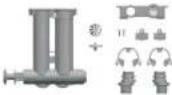 |
| 4. Insert the turbine, turbine positioner and valve connector in the correct order. | 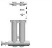 |
| 5. Place the assembled bypass valve in the valve connector. | 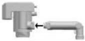 |
| 6. Position the washer so as to connect the bypass valve and connector. | 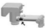 |
| 7. Use a screwdriver to tighten the right and left washers. | 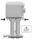 |
| 8. Insert the inlet and outlet connectors into the bypass valve. | 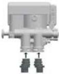 |
| 9. Insert the bypass valve clamps and secure with the inlet and outlet connectors. |  |
| 10. Insert the flow meter into the flow meter seat. |
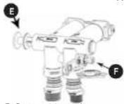
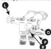
Brine flow controller (BLFC)
A. Quick-connector
D. element 1
C. element 2
D. n°/mm²
E. Bringe port
CAUTION: The end of the Element 3 must be inserted into the brine port first.
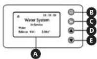
Control panel manual
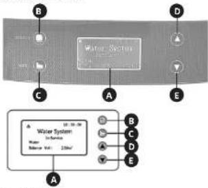
A. Display
B. "Select" button (select)
C. "ESC" button (exit)
D. "UP" Button (up)
L. DOWN BUTTON (DOWN)
1. Display
a) In the service status, the display screen cyclicly shows the following images every 3 seconds:
System efficiency for the deposit regeneration, eg 2.00 m².
| 10:30:00 |
| Water System |
| In-Service |
| Water |
| Balance Vol: 2.00m ^3 |
Temporary water flow speed, eg 1.00 m³/h.
| 10:30:00 |
| Water System |
| In-Service |
| Water |
Regeneration start time, eg 02:00
10:30:00
Water System
In-Service
Water
Trig Time: 02:00
Hint: The current time is displayed in the upper right corner, e.g. 10:30:00
b) When the device operates in other modes, the following messages are displayed:
| Operation status | Display message Description | |
| Backwash Info#tion | 10:30:00Water SystemBack Washing...Left : 2Min | about the remaining rinse time is displayed, e.g. 2 min. |
| Brining and slow rinsing | 10:30:00Water SystemBrine & Slow Rinse ...Down-HowLeft : 30Min | Information about the remaining time until the end of the process is displayed, e.g. 30 min. |
| Drine refilling | 10:30:00Water SystemRefilling ...Left : 5Min | Information about the remaining time until the end of the process is displayed, e.g. 5 min. |
| Fast rinsing Information | 10:30:00Water SystemFast Rinsing ...Left : 3Min | about the remaining time until the end of the process is displayed, e.g. 3 min. |
| Engine works | Motor Running ... | Information about switching between operation processes. |
| Keys blocked | Key LockedPress v.d.s key for 5 seconds to unlock | Press the "UP" button, then the "DOWN" button and hold them both down for approximately 5 seconds to unlock the keys. |
| Controller failure | System Maintenance!** Error 1 ** | When this message appears, contact the manufacturer's service. |
- 'Select' button
a) Press the "Select" button to enter the menu. Use the "UP" and "DOWN" buttons to change the position on the list.
b) After entering the menu and choosing the parameter, press the "Select" button again to choose the parameter to be set. The parameter will start flashing. c) After setting the parameter, press the "Select" button, the device will emit a sound signal confirming acceptance of the entered data. The display will return to its initial state. - ESC button
a) Press the "ESC" button when the menu mode is inactive in order to stop the current operating state and immediately move to the next one. This button allows you to manually control the system.
b) Pressing the "ESC" button while the menu mode is active will cause exit to the settings menu level.
c) Pressing the "ESC" button while entering the settings will cause exit to the setting level (the parameter being set will not be saved). - "LP" and "DOWN" buttons
a) The button is used to change the position on the list and change parameters.
b) Pressing the buttons simultaneously for 5 seconds will unlock the keys. - Other information:
a) Time is displayed in 24h mode.
b) Flow intensity unit: m
c) When the display shows, it means that the keys are locked.
d) Pressing and holding the "UP" or "DOWN" button will continuously change the parameter (increasing or decreasing) until the button is released.
Controller settings - User settings After unlocking the keys, press the "Select" button to enter the menu.
| Set 12/24 Hour Clock |
| Set Clock |
| Set gal/m3/L |
| Set Regen Time |
| Set Resin Vol. |
| Set Water Hardness |
| Set Regen Ratio |
| Set Backwash |
| Set Brine |
| Set Refill |
| Set Fast Rinse |
| Set Regen Day |
| Water Used Today |
| Average Water Used |
a) The clock format setting (Set 12/24 Hour Clock)
| Set 12/24 Hour Clock○12Hour◎24Hour |
b) Clock setting (Set Clock)
Set Clock 12:00
c) The volume unit setting (Set gal/ m3/L)
Set gal/m³/L ○ gal ◎ m³ ○ L
d) Setting time when the regeneration starts (Sat. Page Time).
(Set Regen time)
Set Regen Time 02:00
e) Setting the resin volume (Set Resin Vol.)
Set Resin Vol. 025 L.
CAUTION: The value 008 is given as an example. Do not change the parameter as it may cause improper device operation.
f) Setting water hardness (Set Water Hardness)
Set Water Hardness 5.0 mmol/L
g) Settling the value factor of the brine resin regeneration range (Set Regen Ratio)
Set Regen Ratio 0.65
h) Setting the backwash (Set Backwash)
Set Backwash 02:00 (Min:Sec)
1) Setting brining time (Set Brine)
Set Brine 30:00 (Min:Sec)
j) Setting the brine refilling (Set Refill)
Set Refill 05:00 (Min:Sec)
k) Setting the fast rinsing (Set Fast Rinse)
Set Fast Rinse 03:00 (Min:Sec)
i) Setting time regeneration (Set Regen Day) Temporary - after the appropriate number of days. It is recommended to leave the standard setting, i.e. 30 days.
18 19EN EN
Set Regen Day 30 Days
m) Water used counter for each day (Water Used Today)
Water Used Today 1.00 m ^4
n) Average water used-counter. (Average Water Used)
Average Water Used 5.00 m ^3
- System settings menu After turning on the device, while displaying the valve type (e.g. ASD2), press the "ESC" and "DOWN" buttons to display the system settings menu.
Set Language Set Mode Set Valve Type Set Work Mode
Caution: The value of these parameters has been set by the manufacturer. Do not change the factory settings, as this may affect the operation of the device.
a) The menu language setting (Set Language)
Set Language ◎ English ○ 中文 ○ Spanish
b) Setting the mode: Purifier/Softener (Purifer)/Entharter (Softener)
Set Mode ○Purifier ◎Softener
c) Setting the valve type (Set Valve Type)
Set Valve Type ◎ASD2 ○ASD4 ○ASD10
Caution: Do not change the parameter, otherwise the valve will not work properly. d) The operating mode setting (Set Work Mode)
07.09.2023
| Operating mode | Type Description | |
| A-01 Flow meter delayed start-up | If the available amount of processed water drops to zero, regeneration will start according to the user settings (see previous point). | |
| A-02 Flow meter immediate start-up | If the available amount of processed water drops to zero, regeneration will start immediately. | |
| A-03 Intelligent flow meter delayed start-up | The system calculates the capacity based on the amount of resin, the raw water hardness, and the regeneration rate. If the available amount of processed water drops to zero, regeneration will start according to the time set by the user. | |
| A-04 Intelligent flow meter immediate start-up | The system calculates the capacity based on the amount of resin, the raw water hardness, and the regeneration rate. If the available amount of processed water drops to zero, regeneration will start immediately. | |
| A-05 Flow meter delayed start-up: one day delay | The system will start regeneration after the number of days set by the user in the "Set Regan Day" menu item has elapsed. | |
| A-06 Flow meter immediate start-up after a given time. | The system will start regenerating after the time set in "Set Regan Time" menu item has elapsed. | |
ej Output signal setting [Set Output Signal]
Set Output Signal b-01
Caution: The value of these parameters has been set by the manufacturer. Do not change the factory settings, as this may affect the operation of the device.
Manual starting the regeneration process In the service mode, press the "ESC" button, you will hear the sound of the working engine. The display will show:
Motor Running ...
After few seconds the display will show:
10:30:06 Water System
Back Washing...
Left:2Min
If it is required to complete the procedure, press the "ESC" button. The device will immediately go to the next operation mode. If the ESC button is not pressed, the system will go through the regeneration process.
The remaining steps of the regeneration process can be seen in the following list:
Water System Brine & Slow Rinse ... Down-Flow Left : 30Min
10:30:00 Water System
Refilling
Left:5Min
10:30:00 Water System
Fast Rinsing ...
After the regeneration process is finished, the softener returns to a normal operation mode (the service mode).
3.3. CLEANING AND MAINTENANCE
a) Before starting repairs, replacing accessories, or if the device is not in use, disconnect the device from the power supply and shut off the water supply.
b) Use only mild, food-safe detergents to wash the device.
c) After cleaning the device, all parts should be dried completely before using it again.
d) Store the unit in a dry, cool place, free from moisture and direct exposure to sunlight.
c) Do not spray the device with a water jet or submerge is in water.
f) The device must be regularly inspected to check its technical efficiency and spot any damage.
g) Use a soft cloth for cleaning.
PL PL 20 21
INSTRUKCJA OBSŁUGI
DANE TECHNICZNE
Set clock Set-val/m ^5 /t
Set gat/m²/L
Set Regen Time
Set Resin Vol.
Set Water Hardness
Set Water Hardness Set Power Ratio
Set Regen Kar
Set Backwash
Set Brine
Set Refill
Set Fact Rings
Set Fast Kinse
Set Regen Day
Water Used Today
Average Water Used
Obtokovy ventli (bypass)
A. Displej
B. Tlačitko „Select“ (vybrat)
C. Tlačitko „ESC“ (vybrat)
D. Tlactiko, UP (nanor
E. Tlačitko „DOWN“ (dolů)
- Displej
| Set Mode |
| ○Purifier |
| ◎Softener |
Set Output Signal b-01
E. Steo pistone bypass
UNI WATERSOFTENER 750,
UNI_WATERSOFTENER_500
A. Display
B. Pulsante „Select“ (seleziona)
C. Pulsante, ESC' (esci)
D. Pulmonary UPA (cut)
E. Pulsante „DOWN“ (giú)
- Display
Set Mode ○Purifier ◎Softenc
Set Output Signal b-01
Set Pass Kinoc Set Pass Dr
Set Regen Day
Water Used Today
Average Water Used
(Average Water Used)
Average Water Used
5.00 m ^3
Set Output Signal b-01
UNI WATERSOFTENER 750,
UNI_WATERSOFTENER_500,
UNI WATERSOFTENER 3500
(Average Water Used)
Average Water Used 5.00 m ^4
Set Mode ○Purifier ◎Softener
Set Output Signal b-01
A. Monteringsklemme
B. Blandingsventil
C. Regulator for vandets hardred
D. Bypassventllkalabinet
E. Vandtaellertllslutning
F. Vandatløbs-drejeknap
G. Stor klemme
H. Tillslutning
Sáledes ábnes for del blodgjorte vand
L. Vand flyder gennem venulen
A. Display
D. "Select"-knap
C. "ESC" -knap (forlad)
D. "UP" - knap (gå op)
E. 'DOWN' knap (gà ned)
- Display
μ indouling of supplering of saltvand (Set Refill)
Set Refill
05:00 (Min:Sec)
3.1 APPARAATDESCHRIMING
3.2. WERKEN MET HET APPARAAT
A. Montageklem
B. Menckiep
Leveringspositive onthard water
L. Bypass-zulgerstang
O. Moer inlaatklep
F. Bond Inzetstuk
B. Klein Inzetstuk
NL
Set Regular Full Set Reason Vol
Set Resin Vol.
Set Water Hardness
Set Regen Ratio
Set Backwash
Set Brine
Set Refill
Set Remi
Set Fast Rinse
Set Regen Day
Water Used Today
Average Water Used
(Average Water Used)
Average Water Used
5.00 m³
- Menu systeeminstellingen
| Set Mode |
| ○Purifier |
| ◎Softener |
c) Stel net ventleltype in (Set Valve Type)
| Set Valve Type |
| ○ASD2 |
| ○ASD4 |
| ○ASD10 ↓ |
Set Output Signal b-01
FÖRKLARING AV SYMBOLERNA
Bypassventil (bypass)
Brine flow controller (BLFC)

A. Snabbkoppling
| B. element 1 |
| C. element 2 |
| D. element 3 |
| E. Brine port |
m = 311
Snabh
skolpinos
- 2017年1月1日
1
1
1
1
1
Molom
lungener
1
1
1
- 2014
Mycklen
DASERIF
1
1
1
1
-
Control-
krfel
1
1
1
(No text)
- "VS"
a) Tryck
“UP”
pa
b) After a
pà
som
d Efter
kna
bek
åter
(1)
- ESC
a) Tryck
for
ga
mal
b) Um of
al al
C
gut
1150
1.1.2
96 97 SESE
Set Mode ○Purifier ©Softenc
Set Output Signal b-01
NAMEPLATE TRANSLATIONS
| LNIPRODO | expondo.com | |
| 1 | Product Name | Water Solutioner |
| 2 | Model | |
| 3 | Voltage / Frequency | |
| 4 | Flow Rate | |
| 5 | Working Pressure | |
| 6 | Production Year | |
| 7 | Serial No. | |
| 8 | Manufacturer expendo Polski sp. z o.o. sp. ul Nowy Ksichna-mrzescyjra 7, 06-002 Zielons Gona Polane, SU | CE |
| 1 | 2 | 3 | 4 | 5 | |
| DE Produktname Modell Voltage/Frequency Durchflussrate | |||||
| EN Product Name Model Spannung/Frequency Flow Rate | |||||
| PL | Nazwa produktu | Model | Napiecie znamionowe/Czestatliwość | Prędkość przepływu | |
| CZ | Náczev výrobku | Model | Jmenović nepaljeć napětí/Frekvence | Průček | |
| PR | Nom du produit | Modelo | Tension/Fréquence | Débit | |
| IT | Nome del prodotto | Modello | Tensione/Frequenza | Portato | |
| ES | Nombre del producto | Modelo | Voltaje/Frequencia | Caudal | |
| 5 | 6 | 7 | 8 | 9 | |
| DE | Arbeitsdruck | Produktionsjahr | Ordnungsnummer | Hersteller | |
| EN | Working pressure | Production year | Serial No. | Manufacturer | |
| PL | Cianlenie robouze | Rok produkcji | Numer seri | Producent | |
| CZ | Pracovni itak | Rok výroby | Sarlové číslo | Výrobce | |
| PR | Pression de service | Anode de production | Numéro de serie | Fabricant | |
| IT | Pressione di exercizio | Anno di produzione | Numero di serie | Produzione | |
| ES | Presión de trabajo | Año de produzione | Numero de serie | Fabricante | |
For the disposal of the device please consider and act according to the national and local rules and regulations.
CONTACT
expondo Polska sp. z o.o. sp. k.


- 13EN
- DO NOT USE THE DEVICE UNLESS YOU HAVE THOROUGHLY READ AND UNDERSTOOD THIS USER MANUAL.
- EN
- USAGE SAFETY
- ELECTRICAL SAFETY
- 2.2.SAFETY IN THE WORKPLACE
- PERSONAL SAFETY
- SAFE DEVICE USE
- 15EN EN
- 17EN EN
- 19EN EN
- PL PL 20 21
- Set Output Signal b-01
- NL
- FÖRKLARING AV SYMBOLERNA
- 97 SESE
- Set Mode ○Purifier ©Softenc
- CONTACT
Brand : Uniprodo
Model : UNI_WATERSOFTENER_500
Category : Other kitchen appliances