PrecissionSoldier 650 Vision - Welding machine CECOTEC - Free user manual and instructions
Find the device manual for free PrecissionSoldier 650 Vision CECOTEC in PDF.

User questions about PrecissionSoldier 650 Vision CECOTEC
0 question about this device. Answer the ones you know or ask your own.
Ask a new question about this device
Download the instructions for your Welding machine in PDF format for free! Find your manual PrecissionSoldier 650 Vision - CECOTEC and take your electronic device back in hand. On this page are published all the documents necessary for the use of your device. PrecissionSoldier 650 Vision by CECOTEC.
USER MANUAL PrecissionSoldier 650 Vision CECOTEC
- Parts and components 55
- Before use 55
- Operation 56
- Cleaning and maintenance 57
- Troubleshooting 59
- Technical specifications 60
- Copyright 61
- Technical support and warranty 61
- Declaration of conformity 61
SOMMAIRE
EN · The coding in this manual is generic and applies to all code variants of the appliance.
The instruction manual is part of this product. Contains important safety, use and disposal information. Before using the product, please read all instructions for use and safety. Use the product only as described and for the specified applications.
- The safety instructions provided in this manual do not cover all procedures or problems that may arise when operating, maintaining or cleaning the product.
- Always use common sense and pay special attention to all DANGER, WARNING and NOTICE indications in this manual.
- This is a warning symbol. It is used to warn you of potential injury hazards. Obey all safety messages that follow this symbol to avoid possible injury.
- The equipment is intended for use in the domestic DIY field. It is not designed for commercial, industrial or professional use.
- This appliance is not intended for commercial, industrial or professional use.
- Its commercial, industrial or professional use will void the warranty. Any other use not expressly approved in these instructions may result in damage to the equipment and pose a hazard to the user. The user is responsible for accidents or damage to other people or their property.
- Cecotec is not responsible for damage caused by improper or incorrect use.
- Risk of fire. When using the soldering iron, make sure that the hot tip does not come into contact with combustible materials. Do not leave the appliance unattended while it is hot. Allow it to cool completely down before storing it.
- The soldering tip reaches temperatures of approx. 650 °C. Touching metal parts can cause severe burns.
- The appliance should always be placed on a non-combustible surface when not in use.
- There is a potential fire hazard.
- This product can be used by adults, but also by children aged from 12 years and above and people with reduced physical, sensory, or mental capabilities or lack of experience and knowledge if they have been given supervision or instruction concerning use of the appliance in a safe way and understand the hazards involved.
- Do not allow children to play with the appliance.
- Cleaning and maintenance should not be carried out by children without supervision.
- Always switch on the appliance before it comes into contact with the material to be worked on.
- During the welding process, fumes harmful to health are produced. Good ventilation or adequate vapour removal must be ensured. Protect your eyes with safety goggles and your body with appropriate work clothing against welding spatter and corrosive fumes. It is recommended the use of other PPE (personal protective equipment) such as masks.
- People with electronic devices such as pacemakers should consult their physician before using this product. The use of electrical equipment in the vicinity of a pacemaker may cause interference with or interference to the pacemaker.
- Keep the work area clean and well illuminated. Cluttered workbenches or dark areas can lead to accidents.
- Do not operate power tools in explosive atmospheres, such as in the presence of flammable liquids, gases or dust. Power tools create sparks that can cause fire on dust particles or gaseous fumes.
- Do not expose power tools to rain or wet conditions. Water increases the risk of electric shock.
- Do not use a power tool when you are tired or under the influence of drugs, alcohol or medication.
- Hold the tool by the insulated gripping surface when handling.
DISPOSAL OF OLD ELECTRICAL AND ELECTRONIC APPLIANCES
This symbol indicates that, according to the applicable regulations, the product and/or battery must be disposed of separately from household waste. When this product reaches the end of its shelf life, you should dispose of the cells/batteries/accumulators and take them to a collection point designated by the local authorities.
For detailed information on how to properly dispose of electrical and electronic equipment and/or the corresponding batteries, consumers should contact their local authorities.
Compliance with the above guidelines will help to protect the environment.
INSTRUCTIONS DE SÉCURITÉ
RECICLATGE D'APARELLS ELÈCTRICS I ELECTRÒNICS
EU01_107949 Precision Soldier 650 Vision Full
MODELO: EU01_107948/ EU01_107949
- Cable protector
- Soldering iron handle
- Temperature increase button
- Power button
- Temperature decrease button
- LED display
- Soldering iron cover
- High-temperature resistant union nut
- Fixing nut
- Steel connection tube
- Soldering tip
NOTE:
The graphics in this manual are schematic representations and may not exactly match the product.
2. BEFORE USE
- This appliance comes in packaging designed to protect it during transport. Take the appliance out of its box and remove all packaging materials. You can keep the original box and other packaging materials in a safe place to prevent damage to the appliance if you need to transport it in the future. If you wish to dispose of the original packaging, make sure all items are recycled properly.
- Check that all parts and components are included and in good condition. If any of them are missing or damaged, please contact the Cecotec's Official Technical Support Service immediately.
- Do not remove the serial number of the appliance in order to keep a correct traceability of it in case of assistance.
Box content
EU01_107948 PrecisionSoldier 650 Vision
- Soldering iron
- Soldering tips (x5)
- Soldering iron cover
- Solder wire coil
- Workbench stand
- Instruction manual
ENGLISH
EU01_107949 Precision Soldier 650 Vision Full
- Soldering iron
- Soldering tips (x5)
- Soldering iron cover
- Solder wire coil
- Workbench stand
- Soldering tweezers (x2)
- Wire cutter
- Desoldering pump
- Cable (x2)
- Tip cleaner
- Instruction manual
3. OPERATION
Warning:
Improper use may result in burns and fire hazards. Strictly observe the following:
- Do not touch the metal parts of the soldering tip to avoid burns.
- Do not use it near flammable materials to prevent fire hazards.
- Before replacing the soldering tip, switch off the tool and allow it to cool down.
- Do not wet the soldering iron. Do not operate the soldering iron with wet hands.
- Switch off the soldering iron during breaks and after finishing work and keep it out of the reach of children.
- Do not strike the soldering iron with force to avoid damage.
- Do not modify the soldering iron or replace other parts with unauthorised components.
- Keep it away from children to avoid accidents.
Operating instructions:
- Connect the soldering iron to the mains power supply.
- Press the power button to switch on the tool.
- Press and hold the power button for 3 seconds to switch off the tool.
- Adjust the temperature depending on the type of work to be performed and the material to be soldered. Use the temperature setting buttons to change the temperature in 1 °C increments.
Note: The selected temperature will be automatically saved for future use.
- After setting the temperature, the numbers on the LED display will change until the desired value is reached. Once the target temperature is reached, the numbers will stop flashing and remain steady on the display.
IMPORTANT! Always use the recommended type of solder wire for each soldering task. The use of incorrect solder wire may result in poor joints or component damage. If you have doubts about which type of solder wire to use, always consult the manufacturer's recommendations for the materials or components you are soldering.
WARNING: Do not heat solder wire on surfaces that may be damaged by hot solder drips or splashes. Molten solder can cause serious damage to certain materials.
Always work in designated soldering areas with adequate ventilation and use appropriate safety measures (eye protection, gloves, etc.).
⚠️ BURN HAZARD! Never touch the soldering with your hands to check if it is hot. The tip reaches extremely high temperatures and can cause severe and immediate burns.
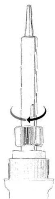
Soldering tip replacement instructions
- Make sure the soldering iron is switched off and unplugged from the mains power supply to avoid any risk.
- Unscrew the fixing nut securing the current soldering tip. Turn the nut counterclockwise as shown in Figure 2.
- Carefully remove the used soldering tip. It may be hot if you have been using the soldering iron recently, so use caution or wait for it to cool down completely.
- Place the new soldering tip, making sure it fits properly inside the steel connection tube and against the heating core.
- Tighten the fixing nut by turning it clockwise as shown in Figure 3 to securely fasten the new tip.
Note: Do not overtighten, just enough to ensure the tip is fixed and does not move.
Standby mode and automatic shut-off. The soldering iron enters standby mode after 30 minutes of inactivity and automatically switches off after 60 minutes of non-use.
4. CLEANING AND MAINTENANCE
To ensure optimal performance and extend the soldering iron's service life, it is important to perform regular cleaning and maintenance. To do it, follow the recommendations below:
Cleaning before use:
- Clean the soldering iron tip regularly, particularly before each new soldering work and when you notice solder or flux residue build-up.
- Dampen a non-abrasive sponge with distilled water and gently wipe the hot tip with it to remove excess solder and residues. Make sure the sponge is only damp, not soaked, to prevent excessive thermal shock to the tip.
ENGLISH
- An alternative to the sponge, especially useful for removing stubborn rust, is using a metal tip cleaner (brass wool). Insert the tip into the brass cleaner and twist gently.
- After cleaning the tip, apply a small amount of new solder to keep it "tinned" and facilitate heat transfer in future soldering operations.
Cleaning after use:
- Clean periodically, e.g., once a month or depending on frequency of use and dirt accumulation.
- Use a soft, slightly damp cloth to clean the handle, cable, and other external parts of the soldering iron. A small amount of mild soap may be used if necessary to remove stubborn dirt.
- Do not over-wet the cloth and make sure no water enters the soldering iron, especially around the buttons or LED display area.
- After cleaning, make sure all parts are completely dry before using or storing the soldering iron.
- Do not use abrasive cleaning agents, strong solvents or immerse the soldering iron in water. This could damage the tool.
Maintenance:
- Check the power cord regularly for signs of damage, cuts or kinks. If you encounter any problems, do not use the soldering iron and contact Cecotec's Official Technical Support Service.
- Check that all connections (tip, fixing nuts, etc.) are secure and properly tightened.

IMPORTANT! Make sure the soldering iron is unplugged and has cooled down completely
before cleaning.
Storage
- Before storing the soldering iron, make sure the tip is clean and lightly tinned to protect it from oxidation during storage.
- Store it in a clean, dry place, preferably in its original box or in a protective case to avoid dust accumulation and potential damage.
- Do not attach the soldering iron cover until the tool has cooled down completely.
5. TROUBLESHOOTING
| Problem Possible cause Possible solution | ||
| The soldering iron does not heat up. | 1. The power cord is not plugged in.2. The power button is in the "off" position.3. Issue with the power socket.4. Internal failure of the soldering iron. | 1. Make sure the power cord is properly connected to both the power socket and the soldering iron.2. Make sure the power switch is in the "on" position.3. Connect and test the soldering iron in a different power socket to rule out issues with the original outlet.4. Contact Cecotec's Official Technical Support Service for inspection or repair. |
| The soldering iron heats up very slowly. | 1. The set temperature is too low.2. Damaged or dirty soldering tip.3. Faulty heating element. | 1. Increase the set temperature to an appropriate level for the type of soldering work you are performing.2. Clean or replace the soldering tip.3. Contact Cecotec's Official Technical Support Service for inspection or repair. |
| The solder wire does not melt properly. | 1. The set temperature is too low.2. Damaged or rusted soldering tip.3. Incorrect type of solder.4. Oxidation on components to be soldered. | 1. Increase the set temperature.2. Clean the soldering tip with a damp sponge or brass tip cleaner.3. Use the proper type of solder for the materials you are soldering.4. Clean the surfaces of the components to be soldered to remove oxidation. |
| Poor solder joints. | 1. Insufficient heat. | 1. Increase the temperature or heat application time. |
| Cold or weak solder joints. | 1. Movement during soldering.2. Dirty or contaminated surfaces.3. Lack of flux. | 1. Make sure the components are stable and immobile during the soldering process.2. Clean the surfaces to be soldered before applying solder wire.3. Use flux to improve solder flow and joint quality. |
ENGLISH
| Problem Possible cause Possible solution | ||
| The LED display does not work. | 1. LED display failure. | 1. Contact Cecotec's Official Technical Support Service for inspection or repair. |
| The soldering tip oxidises quickly. | 1. The working temperature is too high.2. The soldering iron has been left on for extended periods without use.3. Use of harsh flux.4. Low-quality soldering tip. | 1. Reduce the working temperature to an appropriate level.2. Switch off the soldering iron when not actively in use.3. Use a proper, non-corrosive flux.4. Consider using higher quality soldering tips. |
| Problem Possible cause | Solution | |
| The tool does not work. | There is no power supply. | Make sure it is connected to the mains power supply and switched on. |
| It is faulty. | Please contact Cecotec's Official Technical Support Service. | |
| The tool does not heat up enough. | The soldering tip is not properly inserted. | Remove it and let it cool down. After that, remove the soldering tip fixing nut and disassemble it to check that it is correctly positioned. |
| The display does not switch on. | Faulty product. | Please contact Cecotec's Official Technical Support Service. |
6. TECHNICAL SPECIFICATIONS
Product reference: EU01_107948/ EU01_107949
Product: PrecisionSoldier 650 Vision/ PrecisionSoldier 650 Vision Full
Temperature range: 250°C-650°C
Adjustable temperature: ±5°C
Temperature fault: <5 ^ (depending on the contact point of the soldering tip)
Preheating time: 20s
Input voltage: 230 V
Frequency: 50 Hz
Power: Max. 100 W
Technical specifications may change without prior notice to improve product quality. Made in China | Designed in Spain
7. COPYRIGHT
The intellectual property rights over the texts in this manual belong to CECOTEC INNOVACIONES, S.L. All rights reserved. The contents of this publication may not, in whole or in part, be reproduced, stored in a retrieval system, transmitted, or distributed by any means (electronic, mechanical, photocopying, recording or similar) without the prior authorization of CECOTEC INNOVACIONES, S.L.
8. TECHNICAL SUPPORT AND WARRANTY
Cecotec shall be liable to the end user or consumer for any lack of conformity that exists at the time of product delivery under the terms, conditions and deadlines established by applicable regulations.
Repairs should be carried out by qualified personnel.
If at any moment you detect any problem with your product or have any doubt, do not hesitate to contact Cecotec's Official Technical Support Service at +34 96 321 07 28.
9. DECLARATION OF CONFORMITY
MANUFACTURER: CECOTEC INNOVACIONES S.L
ADDRESS: Av. Reyes Católicos, N°60, 46910, Alfafar, Valencia (Spain).
DESCRIPTION: Soldering iron.
PRODUCT IDENTIFICATION: PrecisionSoldier 650 Vision
FUNCTION: Soldering
MODEL: EU01_107948/ EU01_107949
It certifies that the product described has been designed, manufactured and tested and complies with all applicable requirements.
EU DIRECTIVES IMPLEMENTED:
- Directive 2014/35/EU on the harmonisation of the laws of the Member States relating to the making available on the market of electrical equipment designed for use within certain voltage limits.
- Directive 2014/30/EU on the harmonisation of the laws of the Member States relating to electromagnetic compatibility.
ENGLISH
- Directive 2011/65/EU and delegated directive (EU) 2015/863 on the restriction of the use of certain hazardous substances in electrical and electronic equipment.
APPLICABLE HARMONISED NORMS:
- EN 60335-1
- EN 60335-2-45
- EN IEC 55014-1:2021
- EN IEC 55014-2:2021
- EN IEC 61000-3-2:2019+A1
- EN 61000-3-3:2013+A1+A2
- IEC 62321-3-1:2013, IEC 62321-4:2013+A1, IEC 62321-5:2013, IEC 62321-6:2015, IEC 62321-7-1:2015, IEC 62321-7-2:2017
It certifies that the product described has been designed, manufactured and tested and complies with all applicable requirements.
1. PIÈCES ET COMPOSANTS
Image 1
EU01_107949 Precision Soldier 650 Vision Full
MODÈLE : EU01_107948/ EU01_107949
EU01_107949 Precision Soldier 650 Vision Full
MODELL: EU01_107948/ EU01_107949
EU01_107949 Precision Soldier 650 Vision Full
MODELLO: EU01_107948/ EU01_107949
EU01_107949 Precision Soldier 650 Vision Full
MODELO: EU01_107948/ EU01_107949
EU01_107949 Precision Soldier 650 Vision Full
- Soldeerbout
- 5 x soldeertip
- Soldeerbout deksel
- Gratis blikje
- Tafelstandaard
- Klemmen x2
- Kabelschaar
- Desoldeerpomp
- Kabels x2
- Tip reiniger
- Handleiding
3. WERKING
Pas op:
5. PROBLEEMOPLOSSING
OMSCHRIJVING: Soldeerstation.
MACHINE-IDENTIFICATIE: PrecisionSoldier 650 Vision
FUNCTIE: Lassen
MODEL: EU01_107948/ EU01_107949
EU01_107949 Precision Soldier 650 Vision Full
MODEL: EU01_107948/ EU01_107949
MODEL: EU01_107948/ EU01_107949
EU01_107949 Precision Soldier 650 Vision Full
MODEL: EU01_107948/ EU01_107949
EU01_107949 Precision Soldier 650 Vision Full
MINTA: EU01_107948/ EU01_107949
EU01_107949 Precision Soldier 650 Vision Full
MODEL: EU01_107948/ EU01_107949
MONTEΛΟ: EU01_107948/ EU01_107949
IEC 62321-3-1:2013, IEC 62321-4:2013+A1, IEC 62321-5:2013, IEC 62321--
6:2015, IEC 62321-7-1:2015, IEC 62321-7-2:2017
natural_image
Diagram of a mechanical component with a pointed tip and curved arrow indicating rotation (no text or symbols)Fig./Img./Abb./Afb./Rys.2
natural_image
Technical line drawing of a mechanical component with a curved arrow indicating rotation (no text or symbols)Fig./Img./Abb./Afb./Rys. 3
www.cecotec.es