
YT-82555 - Paint spray Yato - Free user manual and instructions
Find the device manual for free YT-82555 Yato in PDF.

| Product type | Paint sprayer (gun + compressor) |
| Brand | Yato |
| Model | YT-82555 |
| Supply voltage | 220-230 V~ |
| Mains frequency | 50/60 Hz |
| Rated power | 1380 W |
| Electrical protection class | II |
| Weight | 6.2 kg |
| Reservoir capacity | 0.8 L |
| Rated flow rate | 1 L/min |
| Nozzle diameters | 1.0 / 1.8 / 2.6 mm |
| Sound level (pressure LpA ± K) | 85.20 ± 3.00 dB(A) |
| Sound level (power LwA ± K) | 96.20 ± 3.00 dB(A) |
| Vibration level ah ± K | < 1.5 m/s² |
| Protection rating | IPX0 |
| Package contents | Compressor unit, spray gun, hose, reservoir, viscosity cup |
| Main functions | Paint spraying, flow and spray pattern adjustment, interchangeable nozzles |
| Safety equipment | Goggles, respiratory protection, hearing protection |
| Maintenance | Cleaning after use with suitable thinner; washable air filter |
| Recommended use | Non-abrasive paints, without large grains, non-corrosive |
Frequently Asked Questions - YT-82555 Yato
User questions about YT-82555 Yato
0 question about this device. Answer the ones you know or ask your own.
Ask a new question about this device
Download the instructions for your Paint spray in PDF format for free! Find your manual YT-82555 - Yato and take your electronic device back in hand. On this page are published all the documents necessary for the use of your device. YT-82555 by Yato.
USER MANUAL YT-82555 Yato
NL HVLP VERFSPUITSET
CE
PL GB DE RU UA LT LV CZ SK HU RO ES FR IT NL GR BG
natural_image
Close-up of hands holding a black cylindrical object with a white handle, no visible text or symbols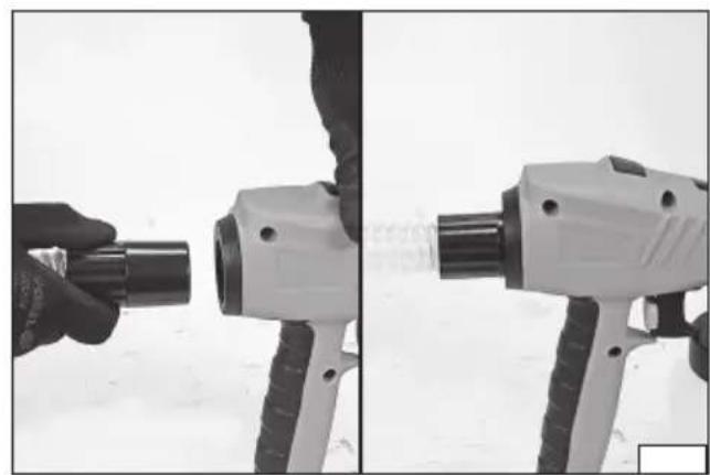
natural_image
Two-panel black-and-white photo showing a hand holding a cylindrical tool, next to a white spray gun with a transparent flame (no text or symbols visible)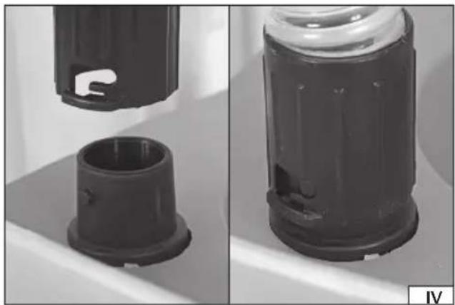
natural_image
Two views of a black plastic device with internal components, one showing a cutaway view (no text or symbols visible)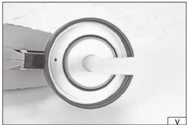
natural_image
Close-up of a mechanical component with concentric rings and a central shaft (no visible text or symbols)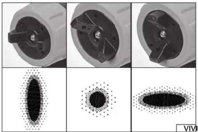
natural_image
Six-panel scientific image showing a mechanical component before and after processing, with corresponding 3D surface plots below (no text or symbols)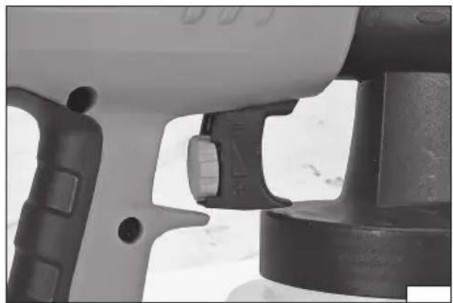
natural_image
Close-up of a mechanical component with no visible text or symbols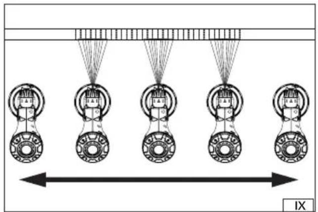
natural_image
Diagram showing mechanical components with arrows indicating motion or force, no text or symbols present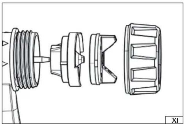
natural_image
Technical line drawing of a mechanical assembly showing exploded and assembled components (no text or symbols)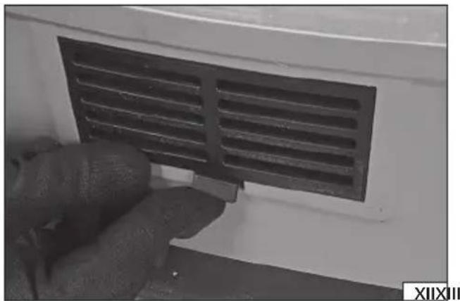
natural_image
Close-up of a hand opening a black ventilation grille on a white wall (no text or symbols visible)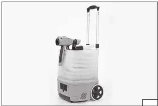
natural_image
Exterior view of a portable industrial water purifier with control panel and fan (no text or symbols visible)
natural_image
Hand holding a flexible hose to lift a transparent cylindrical device (no visible text or symbols)PL
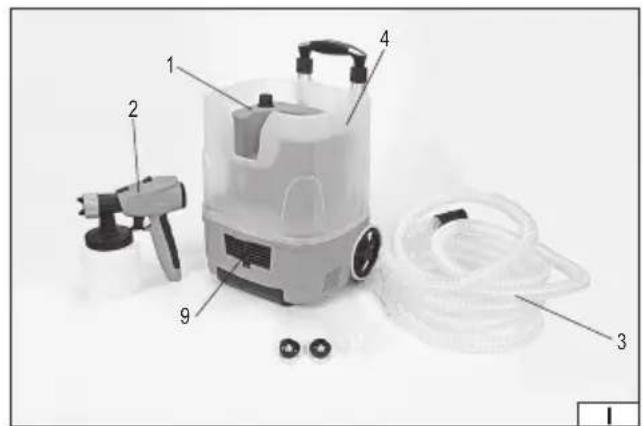
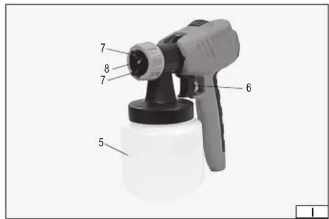
- compressor housing
- spray gun
- air hose
- power switch
- paint container
- trigger
- air nozzle
- spray nozzle
- air fi lter
DE
Read the operating instruction
Second class of insulation
Wear protective goggles
Wear hearing protectors
This symbol indicates that waste electrical and electronic equipment (including batteries and storage cells) cannot be disposed of with other types of waste. Waste equipment should be collected and handed over separately to a collection point for recycling and recovery, in order to reduce the amount of waste and the use of natural resources. Uncontrolled release of hazardous components contained in electrical and electronic equipment may pose a risk to human health and have adverse effects for the environment. The household plays an important role in contributing to reuse and recovery, including recycling of waste equipment. For more information about the appropriate recycling methods, contact your local authority or retailer.
The painting unit is a combination of a paint gun and a compressor supplying compressed air for spray painting. Such solution makes the gun lighter and easier to use while painting. Capacious paint container combined with high performance ensure smooth operation. The correct, reliable, and safe operation of the appliance depends on its proper use, therefore:
Read the entire manual before the first use of the device and keep it for future reference.
The supplier shall not be held liable for any damage resulting from failure to observe the safety regulations and recommendations specified in this manual.
EQUIPMENT
The packaging should include: compressor housing, hose connecting the gun to the compressor, sprayer gun, paint container, and viscometer.
TECHNICAL DATA
| Parameter Unit Value | ||
| Catalogue No. YT-82555 | ||
| Mains voltage [V~] 220 – 230 | ||
| Mains frequency [Hz] 50/60 | ||
| Rated power [W] 1380 | ||
| Electrical protection class II | ||
| Weight [kg] 6.2 | ||
| Tank capacity [l] | 0.8 | |
| Rated capacity | [l/min] | 1 |
| Nozzle diameter | [mm] | 1.0/1.8/2.6 |
| Noise level | ||
| pressure LpA ± K | [dB(A)] | 85.20 ± 3.00 |
| power output LwA ± K | [dB(A)] | 96.20 ± 3.00 |
| Vibration level ah ± K | [m/s2] | < 1.5 |
| Protection rating | IPX0 |
The declared noise emission value has been measured using the standard test method and can be used to compare one tool to another. The declared noise emission value can be used in the preliminary exposure assessment.
The declared total vibration value has been measured using the standard test method and can be used to compare one tool to another. The declared total vibration value can be used in the initial exposure assessment.
Caution! The vibration emission during tool operation may differ from the declared value, depending on the manner the tool is used. Caution! Safety measures to protect the operator, which are based on an assessment of exposure under actual conditions of use (including all parts of the work cycle, such as the time when the tool is switched off or idle and the activation time), must be specified.
GENERAL WARNINGS FOR THE SAFETY OF POWER TOOLS
Warning! Read all safety warnings, illustrations and specifications provided with this power tool. Failure to do so may result in electric shock, fi re or serious injury.
Keep all warnings and instructions for future reference.
The term "power tool" used in warnings applies to all tools driven by power both wired and wireless.
Workplace safety
Keep the workplace well-lit and clean. Disorder and poor lighting can be causes of accidents.
Do not work with power tools in an environment with an increased risk of explosion, containing flammable liquids, gases or vapors. Power tools generate sparks that can ignite dust or fumes.
Children and third persons should not be allowed to enter the workplace. Loss of concentration can result in loss of control. Electrical safety
The plug of the electric cable must match the power socket. You must not modify the plug in any way. Do not use any plug adapters with earthed power tools. An unmodified plug that fits the outlet reduces the risk of electric shock.
Avoid contact with earthed surfaces such as pipes, radiators and coolers. Grounding the body increases the risk of electric shock. Do not expose power tools to contact with atmospheric precipitation or moisture. Water and moisture that gets inside the power tool increases the risk of electric shock.
EN
Do not overload the power cable. Do not use the power cord to carry, pull or unplug the power plug from the power outlet. Avoid contact of the power cable with heat, oils, sharp edges and moving parts. Damage or entanglement of the power cord increases the risk of electric shock.
In the case of working outside closed rooms, use extension cords intended for work outside closed rooms. The use of an extension cord adapted for outdoor use reduces the risk of electric shock.
When using a power tool in a humid environment is unavoidable as a protection against supply voltage use a residual current device (RCD). The use of RCD reduces the risk of electric shock.
Personal safety
Stay alert, pay attention to what you do and keep common sense while working with the power tool. Do not use a power tool when you are tired or under the influence of alcohol or medication. Even a moment of inattention while working can lead to serious personal injury.
Use personal protective equipment. Always wear eye protection. The use of personal protective equipment such as dust masks, anti-slip safety shoes, helmets and hearing protection reduce the risk of serious personal injury.
Prevent accidental operation. Make sure that the electric switch is in the “off” position before connecting to the power supply and / or battery, lifting or moving the power tool. Moving the power tool with the finger on the switch or powering the power tool, when the switch is in the “on” position can lead to serious injuries.
Before turning on the power tool remove any keys and other tools that were used to adjust it. The key left on the rotating parts of the power tool can lead to serious injuries.
Do not reach and do not lean too far. Keep the right attitude and balance all the time. This will allow easier control over the power tool in case of unexpected work situations.
Dress accordingly. Do not wear loose clothing or jewelry. Keep your hair and clothing away from moving parts of the power tool. Loose clothing, jewelry or long hair can be caught by moving parts.
If the devices are fitted for the connection of dust extraction or dust collection, make sure that they are connected and used properly. The use of dust extraction reduces the risk of dust hazards.
Do not let the experience acquired from frequent use of the tool resulted in carelessness and ignoring safety rules.
Carefree action can cause serious injuries in a fraction of a second.
Use and care of the power tool
Do not overload the power tool. Use the power tool appropriate for the selected application. The right power tool will provide a better and safer job if used according to the designed load.
Do not use the power tool, if the electric switch does not allow switching on and off. Power tool, which cannot be controlled by means of a power switch is dangerous and must be returned for repair.
Disconnect the plug from the power socket and / or remove the battery if it is detachable from the power tool before adjusting, changing accessories or storing the tool. Such preventive measures will allow you to avoid accidentally turning on the power tool.
Keep the tool out of the reach of children, do not let people who do not know how to operate the power tool or these instructions use a power tool. Power tools are dangerous in the hands of untrained users.
Maintain power tools and accessories. Check the tool for mismatches or jams of moving parts, damage to parts and any other conditions that may affect the operation of the power tool. Damage must be repaired before using the power tool. Many accidents are caused by incorrectly maintained tools.
Keep cutting tools sharp and clean. Properly maintained cutting tools with sharp edges are less prone to jamming and are easier to control when working.
Use power tools, accessories and inserted tools etc. in accordance with these instructions, taking into account the type and conditions of work. The use of tools for work other than designed is likely to result in a dangerous situation.
Handles and gripping surfaces must be dry, clean and free from oil and grease. Slippery handles and gripping surfaces do not allow for safe operation and control of the tool in dangerous situations.
Repairs
Repair the power tool only in authorized facilities using only original spare parts. This ensures proper operation safety of the power tool.
ADDITIONAL SAFETY INSTRUCTIONS
Always observe the safety instructions in the operating manual as well as the other OHS instructions when using the machine.
Children or persons not trained for the use of spray guns are not allowed to use them.
Never point the device at people or animals.
Do not use spray guns for fl ammable materials.
Do not clean spray guns with fl ammable solvents.
Avoid hazards caused by spraying material and check the marking on the container or the information supplied by the manufacturer on spraying material, including the requirements for the use of personal protective equipment.
Do not spray any materials that may cause an unknown hazard.
EN
Caution! A high-pressure jet can cause severe skin damage. Never allow any part of the body to come into contact with the jet.
Protective clothing does not provide sufficient protection against injuries in the form of injections.
In case of injection of a high-pressure jet under the skin, immediately consult a physician. Inform the physician about the substance injected.
Do not eat, drink or smoke in the working area.
Always wear a respiratory protective mask to protect against harmful vapours.
Ensure adequate ventilation so that there is no accumulation of flammable vapours in the air of the working space.
Appropriate measures should be taken to prevent hazards caused by the substance being sprayed. Follow the instructions given on the packaging or by the manufacturer of the substance to be sprayed.
Do not spray the substances listed as prohibited in this manual.
Do not spray materials of unknown composition.
Do not use the device without the nozzle cover installed.
Never use the device if any protecting elements or covers have been damaged.
Only use original spare parts and carry out any repairs at an authorised workshop.
Disconnect the unit from the mains before performing any servicing works and when it is not used.
Always check that the actual supply voltage corresponds to the voltage indicated on the unit's nameplate.
PREPARING FOR OPERATION
CAUTION! Only install the equipment when the supply voltage is disconnected. Pull the power cord plug from the socket!
Determination of the coating material viscosity
The product is equipped with a viscometer (funnel), which allows to determine whether the viscosity (density) of the paint is appropriate for the gun.
Mix the coating material to be sprayed. The purpose of mixing is to avoid uneven distribution of the coating material density. Immerse the viscometer until it is below the surface of the liquid.
Raise the viscometer above the liquid surface and measure the time needed to empty the viscometer.
Depending on the type of liquid, the viscosity meter must get emptied within 18 s ± 2 s. This is the optimal flow time for working with the largest diameter nozzle.
The density of the coating material may be reduced by using the diluent specified in the documentation accompanying the coating material.
The viscosity should also be adjusted to the diameter of the nozzle used. Smaller diameter nozzles may require material with a lower viscosity – shorter flow time through the viscometer.
Assembly of the unit
Attach the head with nozzle and container to the drive housing. Press the lock button and slide the head into the housing (II). Release the pressure on the lock button, it should automatically return to the initial position. Make sure that the assembly is correct. The head cannot be removed in any other way than pressing and holding the lock button when properly installed.
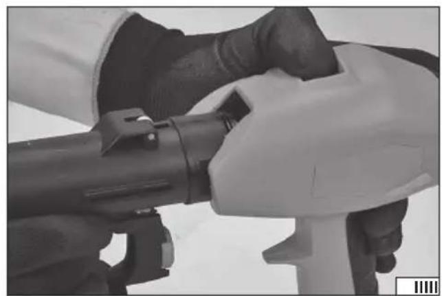
The gun should be connected to the compressor housing with a hose. Push the bevelled cone end of the hose into the air inlet socket at the back of the gun housing (III). Attach the bayoneted tip to the air outlet of the compressor housing. The end of the hose should be placed on the air outlet and then rotated so that the seat pins engage with the holes of the hose end (IV).
The compressor housing allows the hose to be rolled up for transport and storage of the unit. Before starting, the hose should be completely unwound.
Filling and assembly of the paint container
Unscrew the paint container. Push the suction pipe firmly into the mounting opening (V). The end of the suction pipe is bend to help empty the container more accurately when holding the gun at an angle, e.g. when painting floors or ceilings. When turning the suction pipe, point the bent end of the pipe in the opposite direction to the expected inclination of the gun. Fill the container with paint of suitable viscosity. Do not exceed the upper capacity marker of the paint container. Carefully screw the container to the gun and tighten it to seal the connection.
GUN OPERATION
The gun is not suitable for spraying the following paints:
High-density paints – flow time through the viscometer above 100 s.
Paints containing abrasives such as red lead oxide.
Coarse-grained paints.
Corrosive and base paints.
All adjustments of the nozzle must be carried out with the power supply disconnected. To do this, unplug the power cord plug from the socket.
EN
Spray adjustment (VI)
The gun nozzle allows to set the spraying plane and width of the spraying material. The spraying plane can be set by rotating the air nozzles. The air nozzles in a vertical position allow to obtain horizontal spraying plane, and nozzles in a horizontal position allow to obtain vertical spraying plane of the coating material. Setting the nozzles at an angle of 45 degrees will result in obtaining a point spraying plane of the coating material.
Do not place the adjustment elements in positions other than those described in the manual.
CAUTION! Do not press the spray gun trigger button while adjusting the air nozzles.
Adjustment of the amount of spraying of coating material (VII)
Behind the trigger / on/off switch, there is a control knob that limits the depth of the trigger pull. The deeper the trigger is pressed, the more spray material comes out of the spray gun nozzle. Turning the knob clockwise increases the amount of coating material, turning the knob counter clockwise decreases the amount of coating material. The trigger has a mark to facilitate the adjustment.
Switching on/off
Assemble the unit according to the instructions.
Fill the container with the coating material according to the procedure described above.
Make sure that the voltage on the nameplate corresponds to the mains voltage.
Check that the tool switch is in the off position - O.
Make sure that the gun trigger is not pressed.
Plug the power cord plug into the mains socket.
Turn the device on with the switch, move it to the on position - I. Point the gun at a safe place and press the trigger. Adjust the amount of spray material, if necessary, according to the adjustment procedure.
The spraying will stop when the pressure on the trigger of the gun is released.
The device is switched off when the switch is set to the off position.
Painting
It is recommended that the first attempts of spraying the coating material be carried out on the test surface. This will avoid damage to the work area.
Make sure that all surfaces not to be covered are well covered. Make sure that the surface to be covered is clean, dry, degreased and free from dust.
Keep the unit upright so that the nozzle outlet is approximately 20 cm from the surface to be sprayed.
Move the spray gun sideways or up and down so that it is always at a constant distance from the surface to be sprayed (VIII). Start moving the gun and only then pull the trigger. Release the pressure on the trigger before completing the movement of the gun (IX). Moving the spray gun with a steady motion, changing pace or stopping the spray gun during spraying will result in uneven distribution of the coating material.
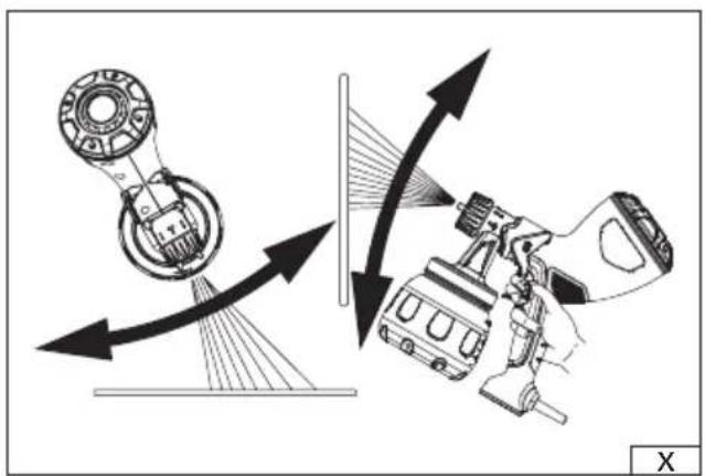
Avoid tilting the gun both horizontally and vertically (X). This will result in an uneven distribution of the coating material.
Apply several thin layers of coating material instead of one thick layer. Before applying the next coat, leave the previous one to dry slightly, follow the instructions supplied with the spray agent.
CLEANING AND MAINTENANCE
Warning! Do not use flammable materials for cleaning and maintenance.
Unscrew the container and clean the interior and exterior of the suction pipe using diluent designed for the coating material immediately after finishing work. Then fill the tank with the diluent intended for the coating material and start spraying it onto the test surface. Stop spraying when the clean diluent is coming out of the nozzle.
Stop spraying, turn off the device, unplug the power cord from the socket, and unplug the hose from the gun and the compressor housing. Then remove the container, empty the rest of the thinner and dry it. Disassemble the nozzle and drive and check the condition of the gaskets. They can be lubricated with a thin layer of silicone grease or technical petroleum jelly. Unscrew the nozzle mounting nut and thoroughly clean all components (XI) with a soft cloth and diluent suitable for the respective coating material.
Remove the suction pipe and check for residual coating material and clean it with a soft plastic bristle cleaner if necessary. Check the condition of the container gasket.
There is an inlet air filter in the compressor housing. Press the clip (XII) slightly and remove the air filter cover. Remove the sponge filter under the cover from the housing and clean it. Clean the filter with a jet of compressed air of not more than 0.3 MPa. If the filter is still dirty after cleaning, replace it. After cleaning the filter, mount the filter and the rear part of the housing in place. Do not use the spray gun without the filter installed, as this may damage the spray gun.
Leaving the spray gun dirty will cause drying out the coating material inside the product. This can lead to irreversible damage to the gun.
Clean the outer parts of the product with a soft, damp cloth and then wipe dry.
Caution! It is forbidden to clean the spray gun by directing a jet at it or immersing it in water, diluent or other liquid. It is forbidden
EN
to use sharp objects and/or abrasive cleaning agents to clean the guns.
Transport and storage
The unit has a space in the housing for placing a coiled hose and a gun. The hose should be rolled up so that its cross-section is not deformed. The gun should be placed with the tank in a place prepared in the housing (XIII). The device has a sliding handle that makes transport easier. The length of the handle can be changed by pressing and holding the button located in the handle holder (XIV). During operation, the handle should be set in the lowest position so that it does not interfere with the operation of the gun.
Keep the product out of the reach of unauthorised persons. The storage area should be protected from precipitation and direct sunlight. Ensure good ventilation in the storage area. Store the product in the working position with the hose disconnected from the gun and the compressor.
GERÄTEBESCHREIBUNG
CARACTÉRISTIQUES DU PRODUIT
DECLARATION OF CONFORMITY
0824/YT-82555/EC/2024
We declare and guarantee with full responsibility that the following products:
HVLP paint sprayer 220-230 V\~; 50/60 Hz; 1380 W; 1 l/ min; item no. YT-82555
meet requirements of the following European Standards / Technical Specifications:
EN 62841-1:2015 + A11:2022
EN 50580:2012 + A1:2013
EN ISO 12100:2010
EN IEC 55014-1:2021
EN IEC 55014-2:2022
EN 61000-3-2:2019 + A1:2021
EN 61000-3-3:2013 + A1:2019 + A2:2021
and fulfill requirements of the following European Directives:
2006/42/EC Machinery and safety elements
2014/30/EU Electromagnetic compatibility (EMC) Directive
2011/65/UE Restriction of the Use of Certain Hazardous Substances
Serial number: concern all serials numbers of item(s) mentioned in this declaration
The person authorized to compile the technical file:
Tomasz Zych
(Place and date of issue)

(Name and signature of authorized person)
TOYA S.A.


