PSKO 2410 B2 - Compressor PARKSIDE - Free user manual and instructions
Find the device manual for free PSKO 2410 B2 PARKSIDE in PDF.

User questions about PSKO 2410 B2 PARKSIDE
0 question about this device. Answer the ones you know or ask your own.
Ask a new question about this device
Download the instructions for your Compressor in PDF format for free! Find your manual PSKO 2410 B2 - PARKSIDE and take your electronic device back in hand. On this page are published all the documents necessary for the use of your device. PSKO 2410 B2 by PARKSIDE.
USER MANUAL PSKO 2410 B2 PARKSIDE
natural_image
Black industrial air compressor with attached propeller unit (no visible text or symbols)SILENT-KOMPRESSOR/SILENT COMPRESSOR/ COMPRESSEUR SILENCIEUX PSKO 2410 B2
DE AT BE CH
SILENT-KOMPRESSOR
Bedienungsanleitung
Translation of the original instructions
FR BE CH
COMPRESSEUR SILENCIEUX
Mode d'emploi

L
List of pictograms used ...... Page 30
Introduction ...... Page 31
Intended use....Page 31
Scope of delivery Page 31
Parts list Page 31
Technical data.... Page 32
General safety instructions.... Page 34
General power tool safety warnings.... Page 34
Safe work Page 36
Additional safety warnings Page 38
Residual risks Page 39
Before first use.... Page 39
Unpacking the product.... Page 39
Assembly Page 39
Fitting the wheels....Page 40
Fitting the supporting foot 40
Fitting the air filter....Page 40
Fitting the transport handle. Page 40
Electrical connection Page 40
Operation....Page 41
Switching on/off Page 41
Setting the pressure....Page 41
Pressure switch setting. Page 41
Connecting the compressed air hose. 41
Using the tyre inflator....Page 41
Using the blow-out pistol....Page 41
Thermal protector....Page 42
Cleaning, maintenance and storage.... Page 42
Cleaning Page 42
Releasing excess pressure.... Page 42
Maintaining the pressure vessel.... Page 43
Safety valve Page 43
Cleaning the air filter....Page 43
Storage Page 43
Transport. Page 44
Spare parts/Accessories Page 44
Troubleshooting Page 44
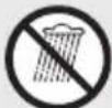
Disposal Page 45
Warranty.... Page 45
Warranty claim procedure. Page 45
Service Page 46
EU Declaration of conformity.... Page 47
| List of pictograms used | |||
 | Read the instruction manual. Wear a  mask! mask! | ||
 | DANGER! This symbol in combination with the signal word “Danger” marks a high-risk hazard that if not prevented could result in death or serious injury. |  | Wear ear and eye protection! |
 | Wear hearing protection! | ||
 | WARNING! This symbol in combination with the signal word “Warning” marks a medium-risk hazard that if not prevented could result in death or serious injury. |  | Warning – hot surface! |
 | Danger – risk of electric shock! | ||
 | CAUTION! This symbol in combination with the signal word “Caution” marks a low-risk hazard that if not prevented could result in minor or moderate injury. |  | Warning – the product is equipped with an automatic start control. Keep others away from the work area of the product! |
 | Do not expose the product to rain. The product may only be stationed, stored and operated in dry ambient conditions. | ||
 | NOTICE! – Warns of possible damage to property/the product if not avoided (e.g. risk of short circuit) |  | Sound power level in dB |
 | Alternating current/voltage |  | Pressure regulator 13 |
 | On/off switch 3 | Safety information Instructions for use | |
 | CE mark indicates conformity with relevant EU directives applicable for this product. | ||
SILENT COMPRESSOR
● Introduction
We congratulate you on the purchase of your new product. You have chosen a high quality product. The instructions for use are part of the product. They contain important information concerning safety, use and disposal. Before using the product, please familiarise yourself with all of the safety information and instructions for use. Only use the product as described and for the specified applications. If you pass the product on to anyone else, please ensure that you also pass on all the documentation with it.
Intended use
The product is designed to generate compressed air for compressed-air driven tools which can be driven with an air volume of up to approx. 180 l/min (e.g. tyre inflator, blow-out pistol and paint spray gun).
Due to the limited air output the product is not suitable for operating tools with very high air consumption (for example orbital sanders, die grinders and hammer screwdrivers).
The tyre inflator is suitable for inflating bicycle tyres, balls, air mattresses, rubber boats, etc.
The blow-out pistol is suitable for cleaning objects and blowing out hard-to-reach areas with compressed air.
■ Use the product in dry, well-ventilated indoor spaces only.
- The product is exclusively intended for domestic use.
■ The product is not intended for commercial or industrial use.
- Only use the product as described and only for the indicated fields of application.
■ Any other use or modification of the product is considered to
be unauthorised use and entails considerable risk of accidents.
The manufacturer assumes no liability for damages resulting from unauthorised use.
The operator or user of the product is responsible for any accidents or personal injury and/or material damage to third parties or their property.
- Scope of delivery
DANGER!
The product and the packaging are not children's toys! Children must not play with plastic bags, sheets and small parts! There is a danger of choking and suffocation!
After unpacking the product, check if the delivery is complete and if all parts are in good condition. Remove all packaging materials before use.
1 Silent compressor
1 Air filter
1 Transport handle
2 Socket screws (M8×25)
1 Supporting foot
2 Wheels
2 Screws
2 Washers
2 Cover caps
1 Compressed air hose
1 Tyre inflator (with hose and pressure gauge)
1 Blow-out pistol
1 Accessory set:
6 Valve adaptors
2 Extension nozzles
1 Ball needle
1 Fixture
1 User manual
Parts list
Before reading, unfold the pages containing the illustrations and familiarise yourself with all functions of the product.
(Fig. A)
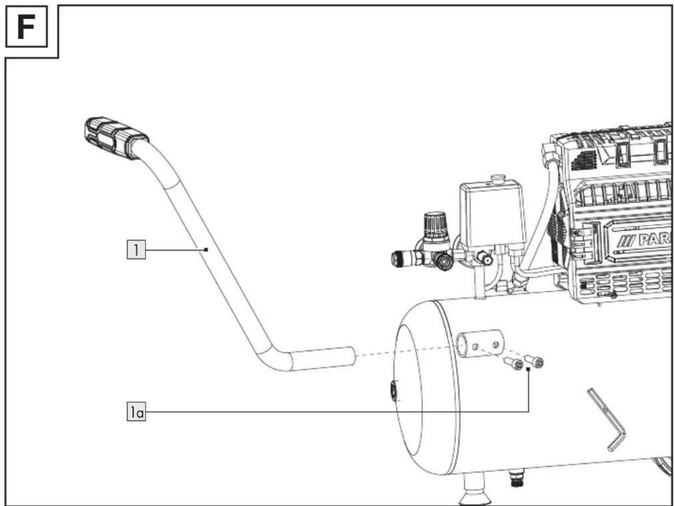
1 Transport handle
1aSocket screws (M8×25)
2 Pressure switch
3 On/off switch
4 Air filter
5 Wheel
6 Drain screw (for condensate)
7 Supporting foot
8 Pressure vessel
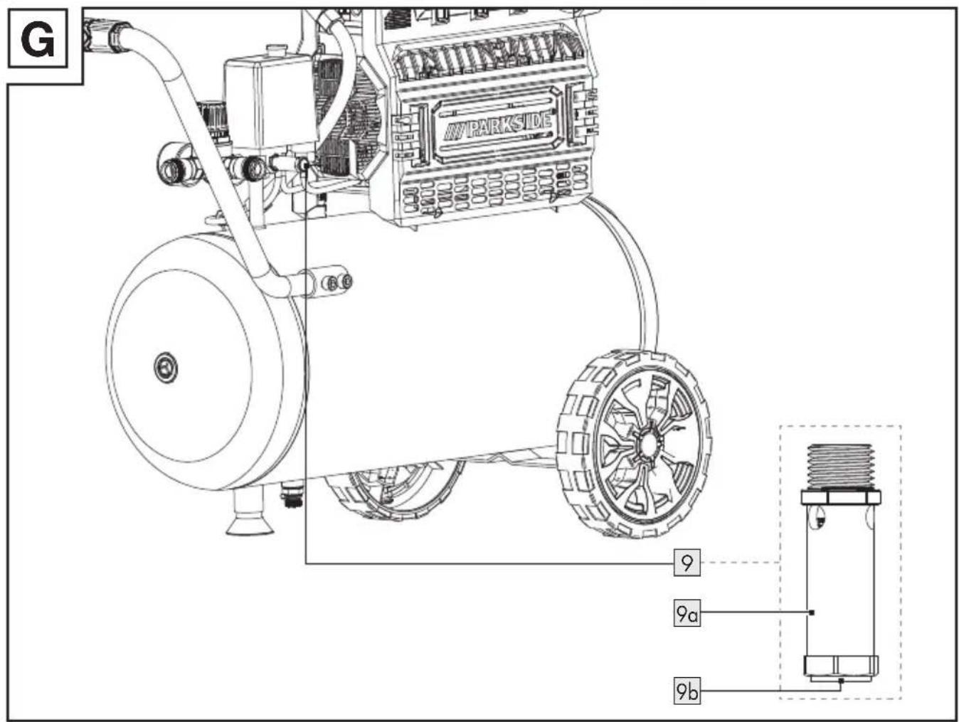
9 Safety valve
10 Quick coupling (regulated compressed air)
11 Pressure gauge (set pressure)
12Pressure gauge (vessel pressure)
(Fig. B)
13 Pressure regulator
(Fig. C)
5aScrew
5b Washer
5cCover cap
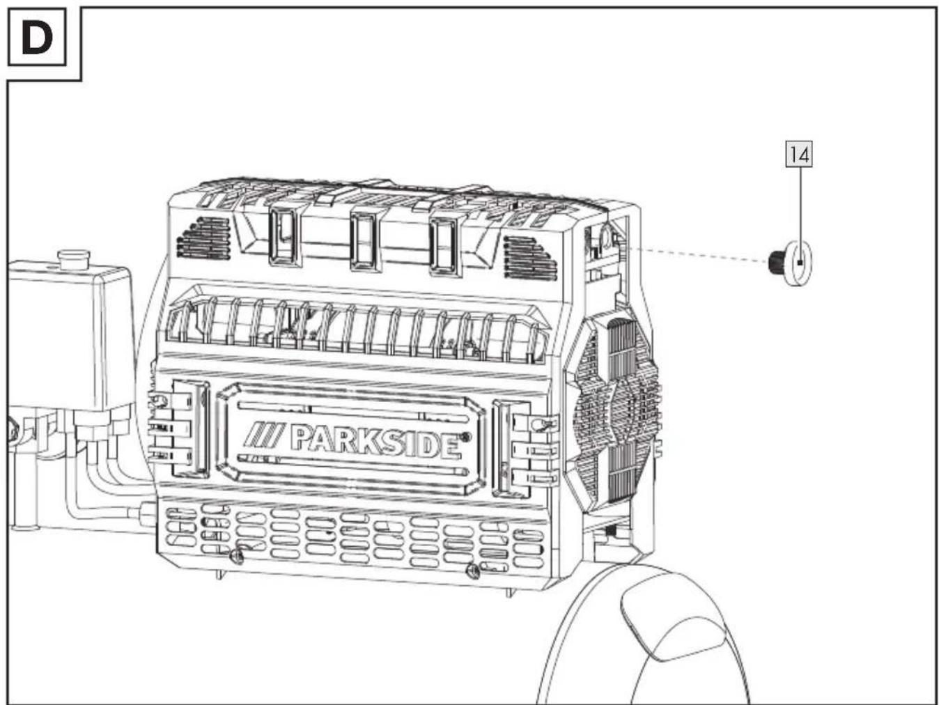
(Fig. D)
14 Transport lid
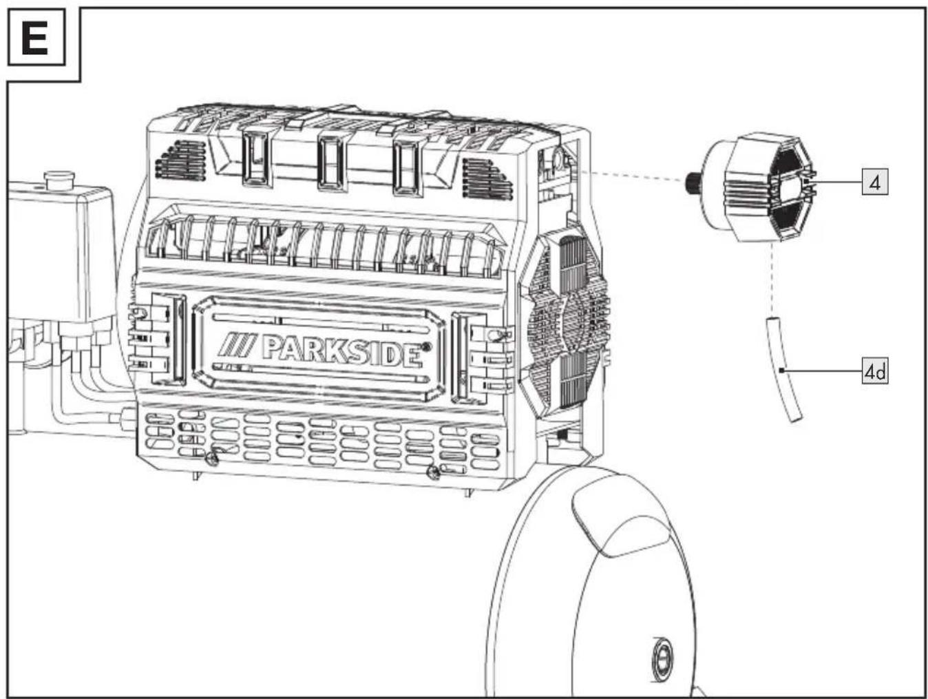
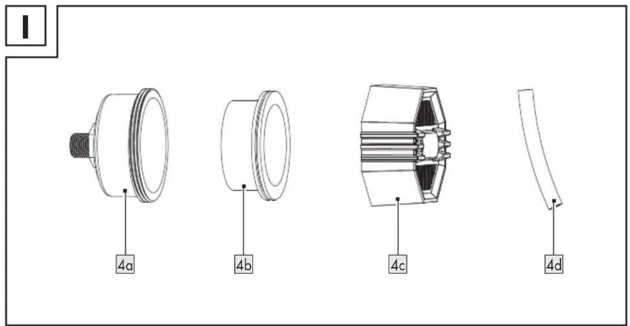
(Fig. E, H, I)
4aFilter housing
4bFilter element
4cFilter cover
4dHose
(Fig. G)
9a Exhaust nut
9bConnection lock
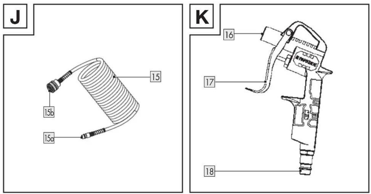
(Fig. J)
15 Compressed air hose
15a Plug nipple
15bQuick coupling
(Fig. K)
16 Blow-out pistol
17Trigger lever
18Plug nipple
(Fig. L)
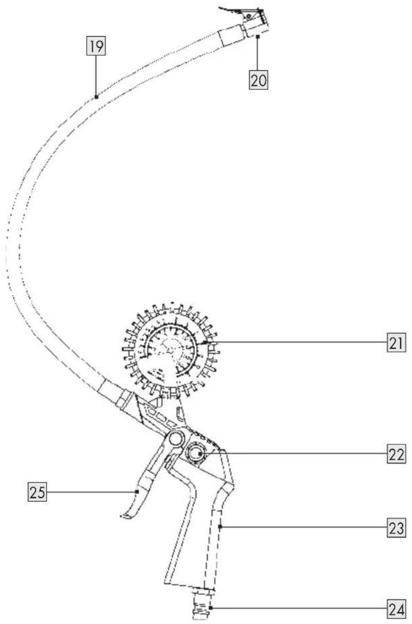
19Hose
20Valve connector
21 Pressure gauge
22Vent valve
23Tyre inflator
24Plug nipple
25Trigger lever
(Fig. M)
26 Extension nozzles
27 Fixture (for adaptors 32 33 34)
28Ball needle
29Universal adaptor (for valves with internal ∅ of 9 mm)
30 Universal adaptor (for valves with internal ∅ of 6 mm)
31 Valve adaptor (e.g. for bicycle tyre valves)
32 Universal adaptor (for valves with internal ∅ of 8 mm)
33Adaptor for threaded valves (e.g. for rubber boats)
34Adaptor for vent valves
● Technical data
| Silent compressor P | SKO 2410 B2 |
| Model number | |
| VDE plug: HG13740 | |
| BS plug: HG13740-BS | |
| Rated input voltage: 230 V~, 50 Hz | |
| Rated input power: 1,500 W | |
| Operating mode: S1 | |
| Compressor speed: 2,850 min -1 | |
| Pressure vessel capacity: 24 l | |
| Operating pressure: approx. 10 bar | |
| Theoretical intake capacity: 214 l/min | |
| Effective delivery quantityat 7 bar: approx. 103 l/minat 4 bar: approx. 141 l/minat 1 bar: approx. 180 l/min | |
| IP protection type: IP30 | |
| Weight: 21 kg | |
| Max. installation altitude (above sea level): 1,000 m | |
| Tyre inflator and blow-out pistol | |
| Model number | |
| Tyre inflator: HG13740A | |
| Blow-out pistol: HG13740B | |
| Operating pressure: max. 10 bar | |
Noise emission value (silent compressor)
The measured values were measured in accordance with EN ISO 3744:2010.
| Sound pressure level L_pA : 69.6 dB | |
| Uncertainty K_pA : 3 dB | |
| Sound power level L_WA : 82.6 dB | |
| Uncertainty K_WA : 1.97 dB | |
Noise emission value (tyre inflator and blow-out pistol)
The measured values were measured in accordance with EN 14462 (EN 1953:2013).
| A-weighted sound pressure level L_pA Tyre inflator: 85.8 dBBlow-out pistol: | 91.5 dB |
| A-weighted sound power level L_WA | |
| Tyre inflator: | 97 dB |
| Blow-out pistol: | 103 dB |
| Uncertainty K: | 2.5 dB |

WARNING!

Wear hearing protection!

WARNING!
The vibration and noise emissions during actual use of the power tool can differ from the declared values depending on the manner in which the tool is used, especially what kind of workpiece is processed.
It is necessary to identify safety measures to protect the operator that are based on an estimation of exposure in the actual conditions of use (taking account of all parts of the operating cycle such as the times when the tool is switched off and when it is running idle in addition to the trigger time).
NOTE
The declared vibration total value and the declared noise emission value have been measured in accordance with a standard test method and may be used for comparing one tool with another.
The declared total vibration value and the declared noise emission value may also be used for a preliminary assessment of exposure.

General safety instructions
● General power tool safety warnings

WARNING!
Read all safety warnings, instructions, illustrations and specifications provided with this power tool. Failure to follow the warnings and instructions may result in electric shock, fire and/or serious injury.
Save all warnings and instructions for future reference.
The term “power tool” in the warnings refers to your mains-operated (corded) power tool or battery-operated (cordless) power tool.
Work area safety
1) Keep work area clean and well lit. Cluttered or dark areas invite accidents.
2) Do not operate power tools in explosive atmospheres, such as in the presence of flammable liquids, gases or dust. Power tools create sparks which may ignite the dust or fumes.
3) Keep children and bystanders away while operating a power tool. Distractions can cause you to lose control.
Electrical safety
1) The mains plug of the power tool must fit into the socket. Never modify the plug in any way. Do not use any adapter plugs with earthed (grounded) power tools. Unmodified plugs and matching outlets will reduce risk of electric shock.
2) Avoid body contact with earthed or grounded surfaces, such as pipes, radiators, ranges and refrigerators. There is an increased risk of electric shock if your body is earthed or grounded.
3) Do not expose power tools to rain or wet conditions. Water entering a power tool will increase the risk of electric shock.
4) Do not abuse the cord. Never use the cord for carrying, pulling or unplugging the power tool. Keep cord away from heat, oil, sharp edges or moving parts. Damaged or entangled cords increase the risk of electric shock.
5) When operating a power tool outdoors, use an extension cord suitable for outdoor use. Use of a cord suitable for outdoor use reduces the risk of electric shock.
6) If operating a power tool in a damp location is unavoidable, use a residual current device (RCD) protected supply. Use of an RCD reduces the risk of electric shock.
Personal safety
1) Stay alert, watch what you are doing and use common sense when operating a power tool. Do not use a power tool while you are tired or under the influence of drugs, alcohol or medication. A moment of inattention while operating power tools may result in serious personal injury.
2) Use personal protective equipment. Always wear eye protection. Protective equipment such as dust mask, non-skid safety shoes, hard hat, or hearing protection used for appropriate conditions will reduce personal injuries.
3) Prevent unintentional starting. Ensure the switch is in the off-position before connecting
to power source and/or battery pack, picking up or carrying the tool. Carrying power tools with your finger on the switch or energising power tools that have the switch on invites accidents.
4) Remove any adjusting key or wrench before turning the power tool on. A wrench or a key left attached to a rotating part of the power tool may result in personal injury.
5) Do not overreach. Keep proper footing and balance at all times. This enables better control of the power tool in unexpected situations.
6) Dress properly. Do not wear loose clothing or jewellery. Keep your hair, clothing and gloves away from moving parts. Loose clothes, jewellery or long hair can be caught in moving parts.
7) If devices are provided for the connection of dust extraction and collection facilities, ensure these are connected and properly used. Use of dust collection can reduce dust-related hazards.
8) Do not let familiarity gained from frequent use of tools allow you to become complacent and ignore tool safety principles. A careless action can cause severe injury within a fraction of a second.
Power tool use and care
1) Do not force the power tool. Use the correct power tool for your application. The correct power tool will do the job better and safer at the rate for which it was designed.
2) Do not use the power tool if the switch does not turn it on and off. Any power tool that cannot be controlled with the switch is dangerous and must be repaired.
3) Disconnect the plug from the power source and/or remove the battery pack, if detachable, from the power tool before making any adjustments, changing accessories, or storing power tools. Such preventive safety measures reduce the risk of starting the power tool accidentally.
4) Store idle power tools out of the reach of children and do not allow persons unfamiliar with the power tool or these instructions to operate the power tool. Power tools are dangerous in the hands of untrained users.
5) Maintain power tools and accessories. Check for misalignment or binding of moving parts, breakage of parts and any other condition that may affect the power tool's operation. If damaged, have the power tool repaired before use. Many accidents are caused by poorly maintained power tools.
6) Keep cutting tools sharp and clean. Properly maintained cutting tools with sharp cutting edges are less likely to bind and are easier to control.
7) Use the power tool, accessories and tool bits etc. in accordance with these instructions, taking into account the working conditions and the work to be performed. Use of the power tool for operations different from those intended could result in a hazardous situation.
8) Keep handles and grasping surfaces dry, clean and free from oil and grease. Slippery handles and grasping surfaces do not allow for safe handling and control of the tool in unexpected situations.
Service
1) Have your power tool serviced by a qualified repair person using only identical replacement parts. This will ensure that the safety of the power tool is maintained.
Safe work
CAUTION!
The following basic safety measures must be observed when using this product for protection against electric shock, and the risk of injury and fire. Read and observe these instructions before using the product.
- Keep the work area orderly.
—Disorder in the work area can lead to accidents.
■ Take environmental influences into account.
—Do not expose the product to rain.
—Do not use the product in a damp or wet environment. There is a risk of electric shock!
—Make sure that the work area is well-illuminated.
—Do not use the product where there is a risk of fire or explosion.
■ Protect yourself from electric shock.
- Avoid physical contact with earthed parts (e.g. pipes, radiators, electric ranges, cooling units).
- Keep the product away from children.
—Do not allow other persons to touch the product or mains cord. Keep children away from your work area.
- Securely store unused electric tools.
—Unused electric tools should be stored in a dry, elevated or closed location out of the reach of children.
■ Do not overload the product.
—The product works better and more safely in the specified output range.
■ Wear suitable clothing.
—Do not wear wide clothing or jewellery, which can become entangled in moving parts.
-When working outdoors, rubber gloves and anti-slip footwear are recommended.
—Tie long hair back in a hair net.
- Do not use the mains cord for purposes for which it is not intended.
—Do not use the mains cord to pull the plug out of the outlet. Protect the mains cord from heat, oil and sharp edges.
■ Take care of the product.
- Keep the product clean so that you can work well and safely.
—Follow the maintenance instructions.
—Check the mains cord of the product regularly and have it replaced by a recognised specialist when damaged.
—Check extension cords regularly and replace them when damaged.
■ Pull the mains plug out of the socket.
—When the product is not in use, prior to maintenance and when replacing parts
- Avoid inadvertent starting.
—Make sure that the product is switched off when plugging the mains plug into an outlet.
■ Use extension cords for outdoors.
—Only use approved and appropriately identified extension cords for use outdoors.
-Only use cable reels in the unrolled state.
■ Remain attentive at all times.
—Pay attention to what you are doing. Remain sensible when working. Do not use the product when you are distracted.
- Check the product for potential damage.
- Protective devices or other parts with minor damage must be carefully inspected to ensure that they function correctly and as intended prior to continued use of the product.
- Check whether the moving parts function faultlessly and do not jam or whether parts are damaged. All parts must be correctly mounted and all conditions must be fulfilled to ensure fault-free operation of the product.
—Damaged protective devices and parts must be properly repaired or replaced by a recognised workshop, insofar as nothing different is specified in the user manual.
—Damaged switches must be replaced at a customer service workshop.
- Do not use any faulty or damaged connection cables.
—Do not use any electric tool on which the switch cannot be switched on and off.
■ Have the product repaired by a qualified electrician.
—This product conforms to the applicable safety regulations. Repairs may only be performed by an electrician using original spare parts. Otherwise accidents can occur.
Attention!
-For your own safety, only use accessories and additional equipment that are indicated in the user manual or have been recommended or indicated by the manufacturer. Use of other tools or accessories than those recommended in the user manual or in the catalogue could represent a personal danger to you.
Noise
—Wear hearing protection when using the product.
■ Replacing the connection line
-If the connection line is damaged, it must be replaced by the manufacturer or an electrician to avoid danger. There is a risk of electrical shock!
Filling tyres
—Check the tyre pressure immediately after filling using a suitable pressure gauge, e.g. at a petrol station.
■ Street-legal compressors in construction site operation
- Ensure that all hoses and fixtures are suitable for the maximum permissible working pressure of the product.
Set-up location
—Only set up the product on a flat surface.
In case of pressures above 7 bar, it is recommended to equip supply hoses with a safety cable (e.g. a wire rope).
Starting the motor is forbidden if the temperature is below 0 °C.
- Avoid over-stressing the piping system by using flexible hose connections to prevent kinking.
- Use a residual current circuit breaker with a trigger current of 30 mA or less. Using a residual current circuit breaker reduces the risk of an electric shock.
Before connecting the product, make certain that the data on the type plate matches with the mains power data.
- Install the product near the point of consumption (compressed air tool).
- Avoid long air lines and supply lines (extension cords).
■ Make sure that the intake air is dry and free of dust.
The product may only be used in suitable rooms (with good ventilation and an ambient temperature from +5 °C to +40 °C). There must be no
dust, acids, vapours, explosive gases or inflammable gases in the room.
The product is designed to be used in dry rooms. It is prohibited to use the product in areas where work is conducted with sprayed water.
The product may only be used briefly outdoors when the ambient conditions are dry.
Additional safety warnings
Observe the corresponding user manuals of the respective compressed air tools/compressed air attachments!
The following general warnings must also be observed.
Safety warnings for working with compressed air and blasting guns
- Ensure there is sufficient distance to the product, at least 2.50 m, and keep the compressed air tools/compressed air attachments away from the product during operation.
The compressor pump and lines can become very hot during operation. Touching these parts will burn you.
The air which is sucked in by the product must be kept free of impurities that could cause fires or explosions in the compressor pump. - When releasing the hose coupling, hold the hose coupling piece with your hand. This way, you can protect yourself against injury from the rebounding hose.
■ Wear safety goggles and a respirator when working with a compressed air pistol. Dusts are harmful to health! Injuries can be easily caused by foreign objects and blown away parts. - Do not blow at people with the blow-out pistol and do not clean clothes while being worn. There is a risk of injury!
Safety warnings when using spraying attachments (e.g. paint sprayers)
- Keep the spray attachment away from the product when filling so that no liquid comes into contact with the product.
■ Never spray in the direction of the product when using the spraying attachments (e.g. paint sprayers). Moisture can lead to electrical hazards! - Do not process any paints or solvents with a flash point below +55 °C. There is a risk of explosion!
- Do not heat up paints or solvents. There is a risk of explosion!
If hazardous liquids are processed, wear protective filter units (face guards). Also, adhere to the safety information provided by the manufacturers of such liquids.
The details and designations of the Ordinance on Hazardous Substances, which are displayed on the outer packaging of the processed material, must be observed. Additional protective measures are to be undertaken if necessary, particularly the wearing of suitable clothing and masks. - Do not smoke during the spraying process and/or in the work area. There is a risk of explosion! Paint vapours are easily combustible.
■ Never set up or operate the product in the vicinity of a fire place, open lights or sparking machines. -
Do not store or eat food and do not drink in the work area. Paint vapours are harmful to your health.
The work area must exceed 30 m^3 and sufficient ventilation must be ensured during spraying and drying. -
Do not spray against the wind. Always adhere to the regulations of the local police authority when spraying combustible or hazardous materials.
- Do not process media such as white spirit, butyl alcohol and methylene chloride with the PVC pressure hose. These media will destroy the pressure hose.
The work area must be separated from the product so that it cannot come into direct contact with the working medium.
Operation of pressure vessels
Anyone who operates a pressure vessel must keep this in good working order, operate and monitor it correctly, perform the necessary maintenance and servicing works immediately and implement safety measures as required according to the circumstances.
■ The regulatory authority can instruct necessary monitoring measures in individual cases.
A pressure vessel must not be operated if it exhibits a defect that poses a danger to personnel or third parties.
- Check the pressure vessel for rust and damage each time before use. The product shall not be operated if the pressure vessel is damaged or rusty. If you discover damage, contact the customer service workshop.
- Residual risks
Even when the product is being used properly, there will always be certain residual hazards that cannot be completely ruled out. The following potential hazards can arise due to the type and design of the product:
■ Unintentional starting up of the product
■ Damage to hearing if the stipulated hearing protection is not worn
- Dirt particles, dust etc. can get into the eyes or face despite wearing safety goggles.
■ Inhaling swirled up particles
WARNING!
This product generates an electromagnetic field during operation. This field can impair active or passive medical implants under certain conditions. In order to prevent the risk of serious or deadly injuries, we recommend that persons with medical implants consult with their physician and the manufacturer of the medical implant prior to operating the product.
Before first use
● Unpacking the product
- Take the product out of the packaging and remove all packaging materials and plastic wrappings.
- Check to make sure that all listed parts are included (see "Scope of delivery").
- Check whether the product and all parts are in good condition, if any damage or defect is detected, do not use the product, but follow the procedure described in chapter "Warranty".
Assembly
NOTICE!
Always make sure the product is fully assembled before commissioning.
- You require the following tools (not included) for assembly:
—Hex key (6 mm)
—Phillips screwdriver
● Fitting the wheels
(Fig. C)
☐ Fit the wheels 5 to the bracket on the underside of the pressure vessel 8.
☐ Fasten each wheel with a screw 5a and a washer 5b.
☐ Tighten the screws 5a with a Phillips screwdriver (not included).
☐ Place the cover caps 5c on the screw heads.
● Fitting the supporting foot
(Fig. C)
☐ Insert the supporting foot 7 into the fixture on the underside of the pressure vessel 8.
● Fitting the air filter
(Fig. D, E)
- Remove the transport lid 14.
- Screw the air filter 4 onto the product.
- Insert the hose 4d into the opening of the air filter 4.
● Fitting the transport handle
(Fig. F)
- Insert the transport handle 1 into the fixture on the side of the pressure vessel 8.
- Fasten the transport handle 1 with 2 socket screws (M8×25) 1a. Tighten the socket screws with a hex key (6 mm, not included).
Electrical connection
WARNING!
The insulation on electrical connection cables is often damaged. This may have the following causes:
—Pressure points, where connection cables are passed through windows or doors
—Kinks where the connection cable has been improperly fastened or routed
—Places where the connection cables have been cut due to being driven over
—Insulation damage due to being ripped out of the wall outlet
–Cracks due to the
insulation ageing
Such damaged electrical connection
cables must not be used and are
life-threatening due to the insulation
damage.
NOTE
In the event of overloading, the motor switches itself off. After a cool-down period (time varies) the motor can be switched back on again.
Long supply cables, extensions, cable reels, etc. cause a drop in voltage and can impede motor start-up.
At low temperatures below +5 °C, sluggishness may make starting difficult or impossible.
Extension cables up to 25 m long must have a cross-section of 1.5 mm ^4 .
□ Connect the mains plug to a suitable socket-outlet.
Operation
- Switching on/off
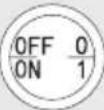
□ Switching on: Pull the on/off switch 3 upwards.
□ Switching off: Press the on/off switch 3 down.
- Setting the pressure
☐ Use the pressure regulator 13 to set the desired pressure on the pressure gauge 11.
☐ The current vessel pressure is shown on the pressure gauge 12.
● Pressure switch setting
■ The pressure switch 2 is set at the factory:
—Start-up pressure: approx. 8 bar
—Shut-off pressure: approx. 10 bar
- Connecting the compressed air hose
☐ Connect the plug nipple 15a of the compressed air hose 15 to the quick coupling 10 of the product.
● Using the tyre inflator
NOTICE!
Before disconnecting the tyre inflator 23 from the compressed air hose 15: Disconnect the compressed air hose from the quick coupling 10 of the product. Otherwise the compressed air hose may whip around in an uncontrolled manner.
-
Connect the plug nipple 24 of the tyre inflator 23 to the quick coupling 15b of the compressed air hose 15. Ensure the plug nipple clicks into place.
-
Using an adaptor (optional):
-Press and hold the lever on the valve connector 20.
—Insert the ball needle 28 or one of the adaptors 29 30 31 into the valve connector 20.
- When using the adaptors 323334: Screw the desired adaptor onto the fixture 27. Insert the fixture into the valve connector 20.
—Release the lever on the valve connector 20.
-
Connect the valve connector 20 (with or without adaptor) to the valve of the object to be inflated.
-
Start inflating: Press and hold the trigger lever 25.
-
While inflating: Check the pressure of the object on the pressure gauge 21.
-
Stop inflating: Release the trigger lever 25.
-
If the object's pressure is too high (i.e. too much air in the object): Press the vent valve 22 to release some air.
-
Disconnecting the valve connector 20 from the valve:
- Without adaptor: Press and hold the lever on the valve connector 20. Pull the valve connector off the valve.
—With adaptor: Pull the valve connector 20 out of the valve.
-
Disconnect the compressed air hose 15 from the quick coupling 10 of the product.
-
Disconnect the tyre inflator 23 from the compressed air hose 15 .
● Using the blow-out pistol
NOTICE!
Before disconnecting the blow-out pistol 16 from the compressed air hose 15: Disconnect the compressed air hose from the quick coupling 10 of the product. Otherwise the compressed air hose may whip around in an uncontrolled manner.
- ☐connect the plug nipple☐☐] of the blo☐☐out pistol☐☐] to the quick coupling☐☐] of the compressed air hose☐☐]. Ensure the plug nipple clicks into place.
- Scre one of the extension nozzles onto the blowout pistol.
- Start blowing out: Press and hold the trigger lever [☐].
- Stop blowing out: Release the trigger lever☐☐].
- Disconnect the compressed air hose[1] from the quick coupling[2] of the product.
- [isconnect the blo-out pistol] from the compressed air hose.
☐ Thermal protector
A thermal protector is built into the product.
- If the thermal protector has tripped, proceed as follows:
- Pull out the mains plug from the socket-outlet.
- Wait for about 2–3 minutes.
- Connect the mains plug to the socket-outlet again.
- If the product does not start, repeat the process.
- If the product does not start again, sitch it o and on again using the on o sitch [3].
- If you have carried out all of the steps above and the product still does not work, contact our Service Centre see Service
□ Cleaning, maintenance
m CAUTION! Risk of injury from electric shock!
u Before carrying out any cleaning and maintenance work: Pull out the mains plug from the socket-outlet.
m CAUTION! Risk of burns!
u Before carrying out any cleaning and maintenance work: Wait until the product has cooled down completely.
m CAUTION! Risk of injury!
u Before carrying out any cleaning and maintenance work: Depressurise the product (see “Releasing excess pressure”
□ Cleaning
☐ Do not use aggressive cleaning agents or solvents; they could attack the plastic parts of the product and accessories.
☐ Make sure that no water can penetrate the interior of the product and accessories.
Do not use water, solvents or similar to clean the product and accessories.
- Before cleaning:
— Disconnect the compressed air hose☐ ] from the ☐ quick coupling☐ ] of the product.
— disconnect the tyre inator or bloout pistol from the compressed air hose.
- Keep the product and accessories as free of dust and dirt as possible. Rub the product and accessories clean with a clean cloth or blow the product of Ⅲ ith compressed air at lo pressure.
- Clean the product and accessories directly after each use
- Clean the product and accessories at regular intervals using a damp cloth and a little soft soap
☐ Releasing excess pressure
- Sitch of the product
- Use the compressed air which is still left in the pressure vessel [8], e. g. with
a compressed air tool running in idle mode or with the blow-out pistol 16.
● Maintaining the pressure vessel

NOTICE! Risk of product damage!
Do not use the product with a damaged or rusty pressure vessel 8. If you discover damage, contact our Service Centre (see “Service”).
☐ Before each use: Check the pressure vessel 8 for rust and damage.
☐ After each use: Drain off the condensate by opening the drain screw 6 to ensure a long service life for the pressure vessel 8.
- Release the vessel pressure (see "Releasing excess pressure").
- Open the drain screw 6 by turning it counter-clockwise (looking at the screw from the bottom of the product).
- In order to drain the condensation water completely out of the pressure vessel 8, tilt the pressure vessel slightly to the side so that the drain screw 6 is the lowest point.
- Close the drain screw 6 again by turning it clockwise.
Safety valve
(Fig. G)
The safety valve 9 has been set for the highest permitted pressure of the pressure vessel 8. Do not adjust the safety valve. Do not remove the connection lock 9b from the exhaust nut 9a.
☐ Actuate the safety valve 9 every 30 operating hours or at least 3 times a year to ensure that it works when required. To do so, proceed as follows:
- Turn the perforated exhaust nut 9a counter-clockwise to open it.
- Open the outlet of the safety valve 9: Pull the valve rod outwards over the perforated exhaust nut 9a by hand. The safety valve audibly releases air.
- Tighten the exhaust nut 9a in clockwise direction.
- Cleaning the air filter
NOTE
The air filter ^4 prevents dust and dirt being sucked in.
It is essential to clean the air filter ^4 after at least every 300 hours in service.
A blocked air filter ^4 significantly reduces the power.
(Fig. H, I)
- Remove the air filter 4: Turn the air filter counter-clockwise.
- Open the filter cover 4c and remove it.
- Remove the filter element 4b.
- Carefully tap out the filter element 4b , the filter cover 4c and the filter housing 4a .
- Blow out the filter element 4b, the filter cover 4c and the filter housing 4a with compressed air (approx. 3 bar)
- Reassemble and install the air filter in reverse order.
Storage
Before storage:
—Pull out the mains plug.
—Ventilate the product and any connected pneumatic tool.
□ Store the product and accessories in such a way that it cannot be used by unauthorised persons.
□ Store the product and accessories in a dry location.
□ Store the product in an upright position, not tilted.
Transport
☐ Use the transport handle 1 to move the product.
☐ Observe the weight of the product when lifting it (see “Technical data”).
☐ When transporting the product in a motor vehicle: Ensure that the load is well secured.
- Spare parts/Accessories
□ Customers can obtain compatible spare parts and accessories via e-mail or our service hotline (see "Service").
□ Have the item number (IAN 504101_2504) ready for your order.
| Spare part Order number | |
| Air filter 4 | 99950410103 |
| Transport lid 14 | 99950410104 |
| Set:■ Whee 5■ Screw 5a■ Washer 5b■ Cover cap 5c | 99950410105 |
| Supporting foot 7 | 99950410106 |
● Troubleshooting
| Problem Possible cause Solution | ||
| The product does not start. | Mains voltage is not available. | Check the mains cord, mains plug, fuse and socket-outlet. |
| Mains voltage is too low. | Make sure that the extension cord is not too long. Use an extension cord with large enough wires. | |
| Outside temperature is too low. | Do not operate the product below +5 °C. | |
| Motor is overheated. | Allow the motor to cool down. If necessary, remedy the cause of the overheating. | |
| The product starts but there is no pressure. | The safety valve 9 leaks. | Contact an authorised service centre. Only allow qualified personnel to carry out repairs. |
| The seals are damaged. | ||
| The drain screw 6 for condensate leaks. | Tighten the drain screw 6 by hand. Check the seal on the drain screw. Replace the seal if necessary. | |
| The product starts, pressure is shown on the pressure gauge 12, but the connected tool does not work. | The hose connections leak. | Check the compressed air hose 15 and compressed air tool and replace if necessary. |
| The quick coupling 10 leaks. | Contact an authorised service centre. Only allow qualified personnel to carry out repairs. | |
| Insufficient pressure set on the pressure regulator 13. | Increase the set pressure with the pressure regulator 13 (see “Setting the pressure”). | |
- Disposal
The packaging is made entirely of recyclable materials, which you may dispose of at local recycling facilities.

Observe the marking of the packaging materials for waste separation, which are marked with abbreviations (a) and numbers (b) with following meaning: 1–7: plastics/20–22: paper and fibreboard/80–98: composite materials.
Product:


The product incl. accessories and packaging materials are recyclable and are subject to extended producer responsibility.
Dispose them separately, following the illustrated Info-tri (sorting information), for better waste treatment.
The Triman logo is valid in France only.

Contact your local refuse disposal authority for more details of how to dispose of your worn-out product.
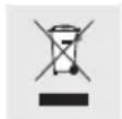
To help protect the environment, please dispose of the product properly when it has reached the end of its useful life and not in the household waste. Information on collection points and their opening hours can be obtained from your local authority.
Warranty
The product has been manufactured to strict quality guidelines and meticulously examined before delivery. In the event of material or manufacturing defects you have legal rights against the retailer of this product. Your legal rights are not limited in any way by our warranty detailed below.
The warranty for this product is 3 years from the date of purchase. The warranty period begins on the date of purchase. Keep the original sales receipt in a safe location as this document is required as proof of purchase.
Any damage or defects already present at the time of purchase must be reported without delay after unpacking the product.
Should the product show any fault in materials or manufacture within 3 years from the date of purchase, we will repair or replace it – at our choice – free of charge to you. The warranty period is not extended as a result of a claim being granted. This also applies to replaced and repaired parts.
This warranty becomes void if the product has been damaged, or used or maintained improperly.
The warranty covers material or manufacturing defects. This warranty does not cover product parts subject to normal wear and tear, thus considered consumables (e.g. batteries, tubes, cartridges), nor damage to fragile parts, e.g. switches or glass parts.
● Warranty claim procedure
So that your request can be processed quickly, please observe the following instructions:
For all inquiries, please have the receipt and item number (IAN 504101_2504) ready as proof of purchase.
The article number can be taken from the identification label on the product, engraving on the product, the front cover of your manual (at the bottom left), or the sticker on the back or bottom of the product.
If malfunctions or other defects arise, first contact the service department indicated below by phone or email.
You can then send a product recorded as defective to the communicated service address postage-free, making sure to enclose proof of purchase (receipt) and information on the details of the defect and when it occurred.

You can download and view this and numerous other manuals at parkside-diy.com. This QR code takes you directly to parkside-diy.com. Choose your country and use the search screen to search for the operating instructions. Entering the item number (IAN) 504101_2504 takes you to the operating instructions for your item.
Service
GB Service Great Britain
Tel.: 08000518970
Contact form on parkside-diy.com IAN 504101_2504
IE Service Ireland
Tel.: 1800851251
Contact form on parkside-diy.com IAN 504101_2504
NI Service Northern Ireland
Tel.: 08081013435
Contact form on parkside-diy.com IAN 504101_2504
CY Service Cyprus
Tel.: 80094242
Contact form on parkside-diy.com IAN 504101_2504
MT Service Malta
Tel.: 80065168
Contact form on parkside-diy.com IAN 504101_2504
● EU Declaration of conformity
EU DECLARATION OF CONFORMITY (No 504101\_2504)
IAN: 504101_2504
Product identification:
"Parkside" Silent compressor
Model Number: HG13740
The object of the declaration described above is in conformity with the relevant Union harmonisation legislation:
| Directive 2006/42/EC |
| Directive 2014/30/EU |
| Directive 2000/14/EC |
| Directive 2005/88/EC |
| Directive 2014/68/EU |
| Directive 2014/29/EU |
| Directive 2011/65/EU and all related amendments |
References to the relevant harmonised standards used or references to the other technical specifications in relation to which conformity is declared:
| N° / Parts |
| Directive 2006/42/EC |
| EN 62841-1:2015/A11:2022 |
| EN 1012-1:2010 |
| Directive 2014/30/EU |
| EN IEC 61000-6-1:2019 |
| EN IEC 61000-6-3:2021 |
| For air blow gun and tyre inflator |
| Directive 2006/42/EC |
| EN 1953:2025 |
The object of the declaration described above is in conformity with Directive 2011/65/EU of the European Parliament and of the Council of 8 June 2011 on the restriction of the use of certain hazardous substances in electrical and electronic equipment:
| N° / Parts |
| EN IEC 63000:2018 |
Conformity Assessment procedure / name&address notified body where appropriate:
Directive 2000/14/EC Annex VI, TÜV SÜD Industrie Service GmbH, Westendstraße 199, 80686 München, Germany
Measured sound power level on an equipment representative for this type: 82.6 dB(A)
Guaranteed sound power level for this equipment: 85 dB(A)
Keeper of the technical documentation: OWIM GmbH & Co.KG
Signed for and on behalf of:
This declaration of conformity is issued under the sole responsibility of the manufacturer.
Translation of the original declaration of conformity
Neckarsulm 23.09.2025
Place
Date

EN
CE
- Activer/désactiver
PDF ONLINE
parkside-diy.com