
YT-55840 - Sweeper Yato - Free user manual and instructions
Find the device manual for free YT-55840 Yato in PDF.

| Product Type | Pneumatic Sandblasting Cabinet |
| Brand | Yato |
| Model | YT-55840 |
| External Dimensions (L x W x H) | 585 x 485 x 494 mm |
| Work Space Dimensions | 580 x 480 x 350 mm |
| Weight (without abrasive) | 17.5 kg |
| Maximum Air Pressure | 0.82 MPa |
| Recommended Working Pressure | 0.27 – 0.82 MPa |
| Air Consumption | 424 – 707 l/min |
| Maximum Abrasive Volume | 6.5 L |
| Recommended Abrasive Grain Size | 0.18 – 0.25 mm |
| Power Supply (Lamp) | 230-240 V ~ 50 Hz |
| Lamp Power | 8 W (12 V DC) |
| Sound Pressure Level | 63.5 dB(A) |
| Vibration Level | Less than 2.5 m/s² |
| Electrical Safety | Double Insulation (Class II) |
| Included Accessories | Sandblasting gun, replacement nozzles, protective gloves, filters |
| Replacement Parts Available | Gloves (YT-55846), protective films (YT-55845), nozzles (YT-55844) |
| Maintenance | Clean filters with compressed air (< 0.3 MPa), drain abrasive, replace worn gloves |
| Storage | In a dry place, sheltered from weather, out of reach of children |
Frequently Asked Questions - YT-55840 Yato
User questions about YT-55840 Yato
0 question about this device. Answer the ones you know or ask your own.
Ask a new question about this device
Download the instructions for your Sweeper in PDF format for free! Find your manual YT-55840 - Yato and take your electronic device back in hand. On this page are published all the documents necessary for the use of your device. YT-55840 by Yato.
USER MANUAL YT-55840 Yato
natural_image
Exterior view of a black industrial machine with open lid and warning label (no readable text beyond branding)CE
natural_image
Two identical cylindrical electronic components with white connectors, mounted on metal frame (no visible text or symbols)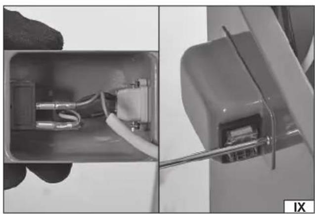
natural_image
Close-up of a hand holding an open electrical socket with wires and components, partially assembled into a close-up view (no visible text or symbols)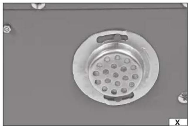
natural_image
Close-up of a circular mechanical component with evenly spaced pins, mounted on a flat surface (no text or symbols visible)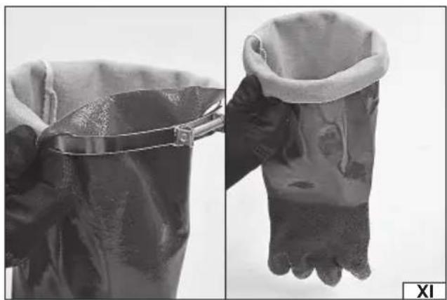
natural_image
Two black-and-white photos showing a hand holding a textured, mesh-like object, with no visible text or symbols.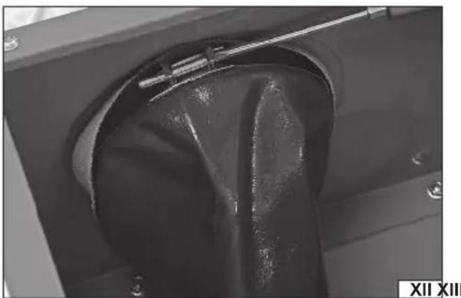
natural_image
Close-up of a mechanical component with a curved black part and a metallic rod inserted, no visible text or symbols.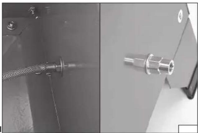
natural_image
Close-up of a mechanical component with a coiled cable and two metallic connectors (no visible text or symbols)PL EN DE RU UA LT LV CZ SK HU RO ES FR IT NL GR
natural_image
Interior view of a mechanical device with gloved hands and wiring, no visible text or symbolsPL
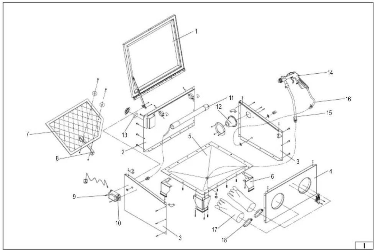
-
lid
-
rear panel
-
side panel
-
front panel
-
bottom panel
-
leg
-
screen
-
screen handle
-
junction box
-
on/off switch
-
lamp
-
cone fi iter
-
flat filter
-
blast gun
-
suction hose
-
supply hose
-
glove
-
clamp
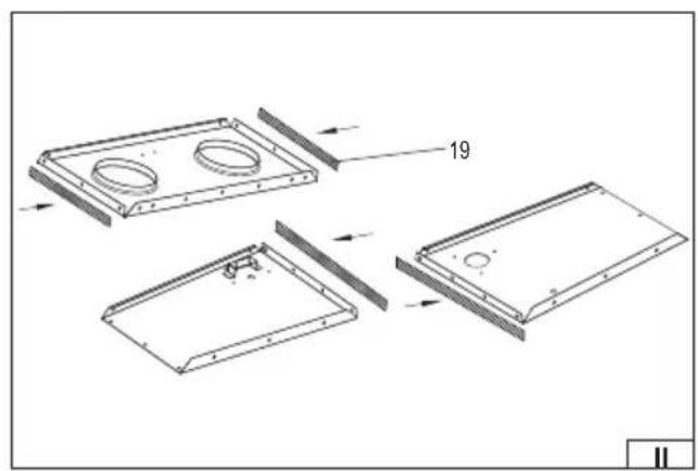
-
sealing tape
DE
Read the operating instruction
Wear protective goggles
Schutzbrille tragen
Wear hearing protectors
Gehörschutz tragen
Second class of insulation
This symbol indicates that waste electrical and electronic equipment (including batteries and storage cells) cannot be disposed of with other types of waste. Waste equipment should be collected and handed over separately to a collection point for recycling and recovery, in order to reduce the amount of waste and the use of natural resources. Uncontrolled release of hazardous components contained in electrical and electronic equipment may pose a risk to human health and have adverse effects for the environment. The household plays an important role in contributing to reuse and recovery, including recycling of waste equipment. For more information about the appropriate recycling methods, contact your local authority or retailer.
PRODUCT CHARACTERISTICS
Sandblast cabinet is a table-top sandblasting tool. Sandblasting is the mechanical removal of rust and/or paint coatings from objects using a jet of abrasive material (abrasive) ejected from the gun nozzle by means of a jet of compressed air. Since sandblasting takes place inside the sealed chamber, a dusting of the abrasive material is limited to a minimum. The correct, reliable and safe operation of the tool depends on its proper use, therefore:
Read and keep this entire manual before the first use of the tool.
The tool supplier shall not be liable for any damage resulting from failure to comply the safety instructions and recommendations specified in this manual.
ACCESSORIES
The unit is delivered disassembled and must be assembled according to the instructions given below before starting work. The product is delivered with a blast gun, additional nozzles and a pair of protective gloves. Abrasive is not supplied with the tool.
TECHNICAL DATA
| Parameter Unit Value | ||
| Catalogue No. YT-55840 | ||
| Maximum pressure [MPa] 0.82 | ||
| Operating pressure [MPa] 0.27 – 0.82 | ||
| Air consumption [l/min.] 424 – 707 | ||
| Outer dimensions [mm] 585 x 485 x 494 | ||
| Working area dimensions [mm] 580 x 480 x 350 | ||
| Maximum abrasive volume [l] | 6.5 | |
| Weight (without abrasive) | [kg] | 17.5 |
| Noise level | ||
| - sound pressure L_pA ± K | [dB(A)] | 63.5 ± 3 |
| - power L_vH ± K | [dB(A)] | 65 ± 3 |
| Vibration Level a_n ± K | [m/s2] | < 2.5 |
| Lamp | ||
| Rated voltage | [VDC] | 12 |
| Rated power | [W] | 8 |
| Lamp power supply | ||
| Supply voltage | [VAC] | 230 – 240 |
| Rated frequency | [Hz] | 50 |
| Output voltage | [VDC] | 12 |
| Output current | [A] | 0.667 |
SAFETY INSTRUCTIONS
Warning! Close and secure the door before starting work. Unsecured doors can cause serious injuries.
Warning! Disconnect the machine from the air and power supply before opening the lid and before performing any maintenance works.
The abrasive and compressed air jets are hazardous. Never point the tool outlet towards people - abrasives or compressed air can cause body trauma or other injuries. Injection of lubricant can cause necrosis or even loss of limb. In case of injection, seek medical attention immediately.
Due to multiple hazards, read and understand the safety instructions before starting installation, operation, repair, maintenance and alteration of accessories or when working in the vicinity of a pneumatic tool. Failure to do so may result in serious injury. Pneumatic tools may only be installed, adjusted and assembled by qualified and trained personnel. Do not modify the pneumatic tool. Modifications can reduce efficiency and safety, and increase the risk for the tool operator. Do not throw away the safety instructions, they should be handed over to the tool operator. Do not use the pneumatic tool if it is damaged.
Operators and service personnel are required to receive appropriate training in the use and repair of the equipment.
It is forbidden to use any other gases instead of compressed air. The use of gases may lead to serious injury, cause fire or explosion. When connecting the tool to the compressed air system, consider the space required for the hose to avoid damaging the hose or connectors.
Effective ventilation should be provided at the workplace. Lack of effective ventilation may result in health hazards, cause fire or explosion. The tool is not intended for use in explosive atmospheres. Use the tool away from heat sources and fire as this may
EN
damage the tool or impair its operation.
Observe the general safety principles when working with spraying materials. Wear suitable personal protective equipment such as goggles, masks and gloves.
There is a risk of absorption of spraying agent or preservative particles during work or when performing maintenance activities, caused by: - insufficient natural or forced ventilation, - improper atomisation pressure, - insufficient optimisation of spray parameters to reduce contamination, - improper distance between tool nozzle and application area of spray agent, the distance should be determined depending on the agent used, - absorption of solvent vapours or other hazardous substances, - improper use e.g. use of improper spray agent.
Never leave the assembled pneumatic system unattended by a person authorised to operate it. Keep children away from the assembled pneumatic system. High-pressure compressed air supply may cause the tool to recoil in the direction opposite to that of the spraying agent ejection. Special care should be taken as jet forces can, under certain conditions, cause multiple injuries. It is recommended to try the tool out before beginning work. It is recommended that persons working with the tool are properly trained. This will signifi cantly increase work safety.
Observe the instructions of the abrasive material manufacturer and use them in accordance with the presented principles for personal, fire and environmental protection. Failure to follow the instructions of the abrasive material manufacturer can lead to serious injury. In order to determine compatibility with the abrasive materials used, a list of materials used for the construction of the tool will be available on request.
When working with the use of compressed air, energy is stored in the entire system. Care must be taken when working and during breaks in order to avoid the risk connected with the stored compressed air energy. Due to the possibility of electrostatic charge build-up, measurements should be taken to ensure whether the tool needs to be grounded, or whether a surface dissipating electrostatic charges and/or compressed air system is necessary. It is required that the measurement and installation of such system is carried out by personnel with appropriate qualifications.
Never point the spray jet at a source of heat or fire, as this may cause fire.
Repairs of the tool can only be performed by qualified personnel using original spare parts.
PRODUCT OPERATION
Tool assembly
Caution! The tool is equipped with adhesive sealing tape, which should be used to seal the sandblasting machine chamber. To disassembly the sandblasting machine, remove the old tape from all the tool elements and replace it with a new one before reassembly.
Apply strips of sealing tape (II) to the shorter edges of the front panel and to the longer edges of the side panels.
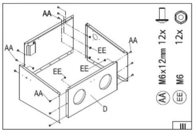
Assemble all four panels of the sandblasting machine chamber (III) together using screws and nuts.
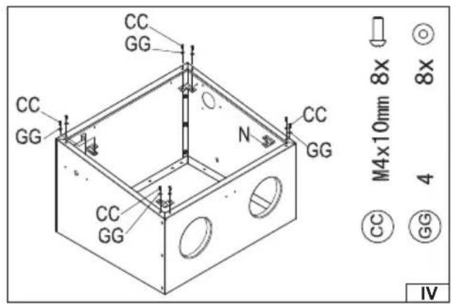
Apply sealing tape to the stiffening connector from the side that comes into contact with the chamber panels, and then mount the stiffening connectors (IV) in the corners at the lower edge of the sandblasting machine chamber using screws and washers.
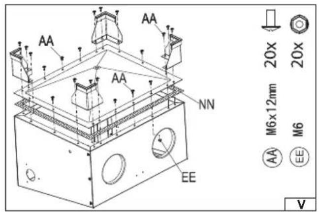
Apply sealing tape to the entire lower edge of the sandblasting machine chamber. Then mount the bottom of the sandblasting machine chamber using screws and nuts. Mount the legs (V) in the corners.
Place the sandblasting machine on legs and mount the cone filter and the lamp handle using screws and nuts inside the sandblasting machine chamber. Install the lid latch (VI) outside the chamber.
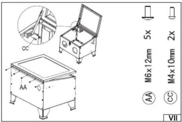
Use the screws to mount the chamber lid and then fix the open lid lock (VII) on the left.
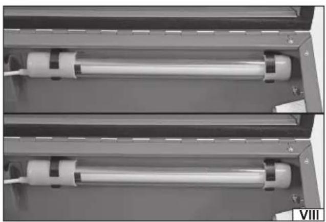
Mount the lamp in the brackets so that the light element is directed towards the interior of the sandblasting machine chamber and having loosened the plastic nut of the opening (VIII), run the lamp cable through the hole in the side panel. Connect the power supply cable wires to the contacts inside a junction box. Make sure the wires are connected in a correct way; the blue wire should be connected to the blue wire and the brown/grey wire to the brown/grey wire. Then fix the junction box to the side panel using screws (IX).
Install a flat filter (X) on the rear panel.
Put the clamp on the glove and then roll back the glove cuff edge onto the clamp (XI). Place the glove inside the sandblasting machine chamber so that the clamp with the rolled back cuff wraps around the opening flange in the front panel of the chamber. Then use a screwdriver to tighten the clamp (XII). Make sure that the right glove is in the right-hand opening and the left-hand glove is in the left-hand opening. Tighten the clamps so that the glove does not slip out from the clamp and is not cut by it.
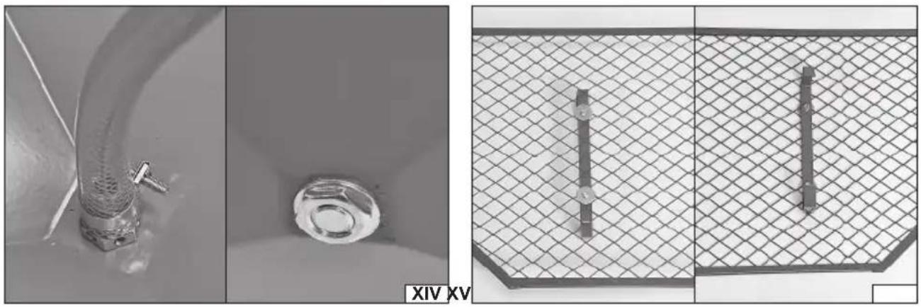
Screw the free end of the compressed air supply hose of the gun (attached to the gun handle) to the hole in the side panel of the chamber (XIII). Screw the free end of the abrasive suction hose (attached near the gun nozzle) to the hole in the bottom of the chamber (XIV).
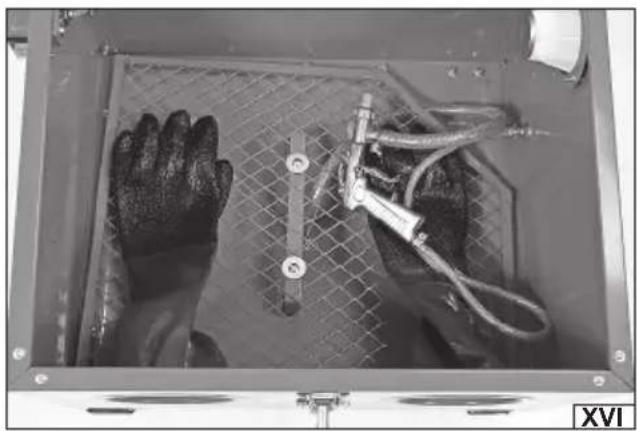
Mount the bracket to the screen using screws and nuts (XV). Place the bracket as close as possible to the screen centre. Place the screen at the bottom of the sandblasting machine chamber with the bracket pointing down so the suction hose runs through a gap made by the screen bevelled corner (XVI).
Abrasive
Make sure that the abrasive is suitable for pneumatic sandblasting machines. The recommended abrasive grain size should be between 0.18 and 0.25 mm. The concentration of harmful substances in the abrasive should not exceed the following levels: - antimony, lead, cadmium, tin, arsenic, beryllium, chromates, cobalt, nickel - total 2% of mass fraction; - arsenic, beryllium, chromates,
EN
cobalt and nickel - total 0.2% of mass fraction; - beryllium, chromates, cobalt, cadmium - separately 0.1% of mass fraction; - metal chemicals should be calculated as metal elements and chromates as CrO_3 ; - pure crystalline silica ( SiO_2 ) - 2% of mass fraction. The abrasive material gets worn out and contaminated during use. Replace the abrasive periodically. Replacement time depends on the work intensity; observe the abrasive colour and the work efficiency. If the colour of the abrasive accumulated in the chamber differs significantly from the colour of the new abrasive, it means significant dirt and in this case the abrasive must be replaced. Similarly, if the efficiency is significantly reduced, the abrasive should be replaced.
The abrasive must be completely dry to ensure that it is free flowing; the flow must be adequate to ensure correct work. Do not store abrasives in humid rooms and do not expose them to sudden changes in temperature. This can lead to condensation of water vapour from the air and moisture in the abrasive.
Caution! Before filling and emptying the sandblasting machine chamber of the abrasive material, make sure that it has been disconnected from the air and power supply. The pneumatic and electric lines must be disconnected from the power supply sources. The abrasive is poured directly into the sandblasting machine chamber. Do not exceed the maximum permissible abrasive volume. The screen should not be covered with abrasive.
When replacing the abrasive, place a container under the sandblasting machine for the used abrasive and then unscrew the end of the suction hose, which is screwed into the bottom of the sandblasting machine chamber. Allow the abrasive to pour into the container. Clean the inside of the chamber with special regard to the thread in the hose opening and connection and screw the end of the suction hose back into the bottom of the sandblasting machine.
Lamp operation
The sandblasting machine has a lamp inside the chamber, which allows to illuminate the interior of the chamber during sandblasting. Use only the lamp supplied with the product. Do not point the abrasive jet directly at the lamp or its cable. This can lead to damage to the lamp or cable, or result in an electric shock. Use only the power adapter supplied with the tool to power the lamp. The power adapter plug should be connected to the junction box. Make sure the on/off switch of the lamp is in the off position - O before connecting the tool to the power supply. Switch the lamp on by moving the switch to the on position - I.
Sandblasting
The air supplying the gun in the sandblasting machine chamber should be filtered and dried. Do not place an oiler in the compressed air supply system. The compressed air supply system for the sandblasting machine must be different from that for supplying pneumatic tools, e.g. wrenches. Make sure that the supply system is of proper performance and that it will provide appropriate pressure. If the air pressure in the supply system is higher than the maximum value in the technical data table and on the nameplate, connect the gun using the pressure reducing valve and pressure gauge that will allow to regulate the pressure. No pressure drop should occur during sandblasting, as this will result in uneven work results.
The sandblasted object should be placed on the screen inside the sandblasting machine chamber; the lid should be closed and secured with the latch. Connect the sandblasting machine to power and pneumatic supply and turn on the lamp inside the chamber. Slide your hands into the gloves and grasp the gun. Point the gun nozzle outlet at the object to be sandblasted, press and hold the gun trigger. The gun trigger release will stop the blow out of the abrasive from the gun nozzle.
Do not hold the sandblasted object in hand when sandblasting. Avoid pointing the abrasive jet directly at the gloves. This will lead to faster wear and tear of the gloves, which may result in glove perforation during operation and cause serious injury.
Use the gun in circular movements over a sandblasted surface. Avoid pointing the abrasive stream at one point. Observe the work results and adjust the pressure. Use the appropriate nozzle. The higher the pressure, the higher the intensity of the abrasive jet, which results in faster and deeper sandblasting. Smaller nozzle diameter allows for more concentrated abrasive jet which results in easier sandblasting of small objects. Larger nozzle diameter allows for wider abrasive jet which results in more effective sandblasting of larger surfaces.
Replace the nozzle by unscrewing the ring around the nozzle, cleaning the nozzle mount, nozzle replacement and mounting it using the ring. Use only the supplied nozzles or the nozzles from the YATO YT-55844 set.
If the nozzle becomes clogged during operation, stop working, disconnect the machine from the pneumatic and power supply, then remove the nozzle and try to clean it. Use a plastic brush for cleaning. Do not use sharp or metal tools. If the cleaning of the nozzle fails, replace it.
Caution! Make sure that the unit has been disconnected from the pneumatic and power supply before any replacement or adjustment works.
Gloves wear out during operation and should be inspected for signs of wear before each use - whether there are no visible signs of damage, abrasion, tears etc. If any, replace the gloves. Sandblasting machine gloves are available separately as YATO YT-55846.
The transparent part of the lid may fade during operation. To prevent loss of visibility, the middle part of the lid is covered with a transparent protective film. Replace the protective film each time the previous one becomes dull and does not allow for work observation. Protective films are available separately as YATO YT-55845.
MAINTENANCE, TRANSPORT AND STORAGE
Warning! Make sure that the unit has been disconnected from the compressed air and power supply before performing any maintenance works, transport or storage.
EN
Before performing any maintenance works, unscrew the hose mount from the sandblasting machine bottom and remove all abrasive. Clean the sandblasting machine chamber using a soft hand broom, a brush or jet of compressed air with pressure not higher than 0.3 MPa. If the abrasive remains in the suction hose, place a small metal container in the sandblasting machine chamber. Close and snap the chamber lid, point the gun nozzle at the container internal part and with the minimum working pressure empty the hose as during work.
Remove the flat and cone filters and clean them with jet of compressed air with pressure not higher than 0.3 MPa. If the filters are too dirty, replace them.
Clean the machine housing with a damp cloth and then wipe dry.
Transport and store the unit in its working position. The place of storage should protect the machine from access by unauthorised persons, especially children. The place of storage should be shaded and well-ventilated to prevent water vapour condensation. The place of storage should provide protection against precipitation. Do not place anything on the machine.
Transport the unit in the working position, emptied of abrasive. In the case of longer transport distances, the machine must be protected against damage by means of an additional packaging (cardboard box, box).
Content of the gloves manual according to EN ISO 21420:2020 standard
Manufacturer: TOYA S.A., ul. Sołtysowicka 13/15, 51-168 Wrocław, Poland. Product description: Protective gloves protecting against mechanical hazards are a personal protection equipment to protect hands. The gloves are designed and manufactured so that the user can freely perform the activities associated with the mechanical hazards involved, having protection at the level specified below, under the conditions of use for which the gloves are intended. The gloves are made of PVC. Persons allergic to these materials may develop an allergic reaction. Recommendations for the use of gloves: Do not use the gloves of improper size, too loose or tight. Do not use damaged, dirty or damp gloves, as they will lose their protective function. Check the gloves for signs of wear and tear or damage before each use. After work, clean the gloves with a brush or cloth. Do not wash or dry-clean. Store the product in a cool, dry, shaded, well-ventilated and closed room, both before and after use. Storage conditions: temperature +5 to 25°C, humidity <60%. Excessive humidity, too high temperature or intense light can adversely affect the gloves quality. The supplier shall not be held liable for the quality of any product not stored in accordance with the recommendations. The gloves should be transported in a cardboard box or plastic packaging. The packaging should provide ventilation. Gloves last for up to two years from the date of purchase when not in use. Gloves should not be worn if there is a risk of being pulled in by moving machine parts. Puncture resistance to the extent specified below does not mean protection against punctures by sharp pointed objects such as needles for injections. Notified body: INTERTEK Italia S.p.A. (2575), Via Guido Miglioli 2/A, 20063 Cernusco sul Naviglio - Milano (MI), Italy. Explanation of the markings: YATO - manufacturer's mark; YT-55846 - manufacturer category number; CE - the marking of conformity with the New Approach Directives; EN 388 - number of the European standard for protective gloves protecting against mechanical hazards; "hammer symbol" - hazard category indicating mechanical hazards; "i symbol" - the sign indicating that supplementary information should be read; 12 (470) - size of the gloves; 3131X - effectiveness levels according to tests in accordance with EN 388; abrasion resistance: level of effectiveness: 3 - the gloves withstand 2000 test cycles; blade cut resistance: effectiveness level: 1 - gloves have an index of 1.2; tear strength: level of effectiveness: 3 - the gloves withstand tearing with a force of 50 N; puncture resistance: performance level: 1 - the gloves withstand a steel mandrel with a force of 20 N: cut resistance according to EN ISO 13997 - X - the test has not been carried out. Puncture resistance as defined below does not mean protection against punctures by sharp pointed objects such as needles for injections. For details on the meaning of the performance levels, please refer to the EN 388 European Standard. Declaration of Conformity: available in the product sheet at toya24.pl.
DE
PRODUKTBESCHREIBUNG
CARACTÉRISTIQUES DU PRODUIT
DECLARATION OF CONFORMITY
0524/YT-55840/EC/2024
We declare and guarantee with full responsibility that the following products:
Sandblaster cabinet; 0,82 MPa; 424 – 707 l/min; 90 l; item no. YT-55840
meet requirements of the following European Standards / Technical Specifications:
EN 60204-1:2018
EN 1248:2001 + A1:2009
and fulfill requirements of the following European Directives:
2006/42/EC Machinery and safety elements
Serial number: concern all serials numbers of item(s) mentioned in this declaration
The person authorized to compile the technical file:
Agnieszka Rędziak
(Place and date of issue)
V-CE PREZES ZARZADU
JAN SZMIDT
(Name and signature of authorized person)
TOYA S.A.
