
Fast&Clean 3000 Agile - Plane CECOTEC - Free user manual and instructions
Find the device manual for free Fast&Clean 3000 Agile CECOTEC in PDF.

| Product type | Electric planer |
| Brand | Cecotec |
| Model | Fast&Clean 3000 Agile |
| Power supply | Mains (power cable) |
| Cutting depth | 0 to 2 mm |
| Main functions | General planing, chamfering (V-groove for 45° bevels), depth adjustment, dust extraction |
| Included accessories | Parallel guide, chip and dust collection bag, spare belt, wrench, Allen key, instruction manual |
| Safety | Switch with lock, protection against accidental start, safety instructions included |
| Maintenance and cleaning | Clean with a dry cloth, brush for hard-to-reach areas, compressed air (max 3 bars); do not use aggressive detergents |
| Spare parts | Blades (pairs), belt, blade holder, hex screws |
| Repairability | Repair by authorized technical service with original parts |
| Storage temperature | 10 °C to 30 °C |
| Standards | EN 62841-1, EN 62841-2-14, EN IEC 55014-1, etc. (CE compliance) |
Frequently Asked Questions - Fast&Clean 3000 Agile CECOTEC
User questions about Fast&Clean 3000 Agile CECOTEC
0 question about this device. Answer the ones you know or ask your own.
Ask a new question about this device
Download the instructions for your Plane in PDF format for free! Find your manual Fast&Clean 3000 Agile - CECOTEC and take your electronic device back in hand. On this page are published all the documents necessary for the use of your device. Fast&Clean 3000 Agile by CECOTEC.
USER MANUAL Fast&Clean 3000 Agile CECOTEC
natural_image
Blue and black electric drill press with tools and a cloth cover, displayed against a dark background (no text or symbols visible on the device itself)Safety instructions 11
-
Copyright 93
-
Declaration of Conformity 93
INDEX
-
Parts and components 94
-
Before use 94
-
Installation 95
-
Operation 96
-
Cleaning and maintenance 98
-
Troubleshooting 100
-
Recycling of electrical and electronic equipment
-
Copyright 101
-
Declaration of Conformity 101
SOMMAIRE
EN · The coding in this manual is generic and applies to all code variants of the appliance.
General power tool safety instructions
⚠ WARNING: Read all hazard warnings, instructions, figures and technical specifications supplied with the power tool. Failure to follow all instructions listed below may result in electric shock, fire and/or serious injury.
Keep all safety warnings and instructions for future reference. The term “power tool” in the warnings refers to your mains-operated (corded) power tool or battery-operated (cordless) power tool.
Work area safety
a. Keep the work area clean and well lit. Cluttered or dark areas may cause accidents.
b. Do not operate power tools in explosive atmospheres, such as in the presence of flammable liquids, gases or dust. Power tools can produce sparks that ignite dust or fumes.
c. Keep children and bystanders away while operating a power tool. Distractions can cause you to lose control.
Electrical safety
a. Power tool plugs must match the outlet. Never modify the plug in any way. Do not use adapters on grounded power
tools. Unmodified plugs and matching sockets will reduce the risk of electric shock.
b. Avoid body contact with grounded surfaces, like pipes, radiators, stoves and refrigerators. There is an increased risk of electric shock if your body is earthed or grounded.
c. Do not expose power tools to rain or wet conditions. Water entering a power tool will increase the risk of electric shock.
d. Do not misuse the cord. Never use the cord for carrying, pulling or unplugging the power tool. Keep cord away from heat, oil, sharp edges or moving parts. Damaged or entangled cords increase the risk of electric shock.
e. When operating a power tool outdoors, use an extension cord suitable for outdoor use. Use of a cord suitable for outdoor use reduces the risk of electric shock.
f. If operating a power tool in a damp location is unavoidable, use a residual current device (RCD) protected supply. Use of an RCD reduces the risk of electric shock. The application of a differential fuse reduces the risk of exposure to electric shock.
Personal safety
a. Stay alert, watch what you are doing and use commonsense when operating a power tool. Do not use the power tool if you are tired, or after consuming drugs, alcohol or medication. Failure to exercise caution when operating the power tool can result in serious injury.
b. Use personal protective equipment. Always wear eye protection. Protective equipment such as dust mask, non-skid safety footwear, helmet or hearing protection, used under appropriate conditions, will reduce personal injuries.
c. Avoid unintentional start-up. Make sure that the power tool is switched off before connecting it to the mains and/or when mounting the battery pack, picking it up and transporting it. If you transport the power tool by holding it by the on/off switch, or if you power the power tool while it is switched on, this may result in an accident. Remove adjustment tools or spanners before connecting the power tool. An adjusting tool or wrench placed on a rotating part can cause injury when operating the power tool.
d. Avoid risky postures. Keep proper footing and balance at all times. This will allow you to better control the power tool in the event of an unexpected situation.
e. Wear appropriate work clothing. Do not wear loose clothing or jewelry. Keep your hair and clothing away from moving parts. Loose clothing, long hair and jewelry can catch on moving parts.
f. If devices are provided for the connection of dust extraction and collection facilities, ensure these are connected and properly used. The use of this equipment reduces the risks derived from dust.
g. Do not let familiarity gained from frequent use of tools allow you to become complacent and ignore tool safety principles. A careless action can cause serious injury within a fraction of a second.
Power tool use and maintenance
a. Do not overload the power tool. Use the correct power tool for your application. With the right power tool you can work better and safer within the specified power range.
b. Do not use the power tool if the switch is faulty. Power tools that cannot be connected or disconnected are dangerous and must be repaired.
c. Disconnect the mains plug and/or remove the detachable battery from the power tool before making any adjustments, changing accessories or storing the power tool. Such preventive safety measures reduce the risk of the power tool starting up accidentally.
d. Keep unused power tools out of the reach of children. Do not allow persons who are unfamiliar with the power tool or who have not read these instructions to use it. Power tools used by inexperienced persons are dangerous.
e. Check the power tool and its accessories. Check if the moving parts are misaligned or stuck, if there are broken pieces or any other condition that may affect the power tool's operation. In case of damage, the power tool must be repaired before use. Many accidents are due to poorly maintained power tools.
f. Keep accessories clean and sharp. Properly maintained accessories are better guided and controlled.
g. Use the power tool, accessories, etc. according to these instructions, taking into account the working conditions and the work to be carried out. The use of power tools for work other than that for which they are intended can be dangerous.
h. Keep handles and gripping surfaces dry, clean and free of oil and grease. Slippery handles and grasping surfaces do not allow safe handling and control of the tool in unexpected situations.
Service
a. Only have your power tool repaired by a qualified expert, using only original spare parts. This is the only way to maintain the safety of the power tool.
Safety warnings specific to brushes
- Wait for the blade to stop before leaving the tool. An exposed blade that is spinning can contact a surface and cause possible loss of control and serious injury.
- Hold the power tool by the insulated gripping surfaces only, as the blade may come in contact with its own cord. If a live wire is cut, exposed metal parts of the tool may also become live and the operator may receive an electric shock.
- Use clamps or other practical clamping devices to secure and support the workpiece to a stable platform. Holding the workpiece by hand or against your body makes it unstable and may lead to loss of control.
- Rags, pieces of cloth, cables, ropes and similar items should never be left in the work area.
- Avoid cutting nails. Before working, inspect the workpiece and remove all nails.
- Use only sharp blades. Handle the blades with care.
- Ensure that the blade mounting bolts are securely tightened before use.
- Hold the tool firmly with both hands.
- Keep hands away from rotating parts.
- Before using the tool on a workpiece, let it run for a few moments. Watch for vibrations or oscillations, which would indicate that the blade has not been installed correctly or is poorly balanced.
- Make sure that the saw blade is not touching the workpiece before activating the switch.
- Wait for the blade to reach full speed before cutting.
- Turn the tool off and always wait until the blade has stopped before making any adjustments.
-
Never insert a finger into the chip chute. The duct may clog when planing wet wood. Clean the shavings with a stick.
-
Do not leave the tool running. Start it only when you have it in your hands.
- Always replace both blades or drum covers; otherwise, the resulting imbalance will cause vibrations and shorten the tool's service life.
- Always wear a dust mask or respirator suitable for the material and application you are working with.
INSTRUCTIONS DE SÉCURITÉ
- On/Off switch
- Locking button
- Main handle
- Belt cover
- Parallel guide
- Mounting hole (Parallel guide)
- Wing nut
- Cutting depth scale
- Cutting depth adjustment knob
- Dust extraction outlet
- Hex screws
- Blade
- Back plate
- Roller
- Blade holder
- Capscrews
- V-groove
- Front plate
- Bag for shavings and dust collection
- Spanner
- Allen key
Note:
The graphics in this manual are schematic representations and may not exactly match the product.
2. BEFORE USE
- This appliance comes in a packaging designed to protect it during transport. Remove the appliance from its box. You can keep the original box and other packaging materials in a safe place to prevent damage to the appliance if you need to transport it in the future. If you wish to dispose of the original packaging, make sure all items are recycled properly.
- Check that all parts and components are included and in good condition. If any of them are missing or damaged, please contact Cecotec's Official Technical Support Service immediately.
Box content:
- Electric planer
- Parallel guide
- Replacement belt
- Bag for shavings and dust collection
- Tools to disassemble the blades
- Instruction manual
- Do not remove the product's serial number in order to keep proper traceability if technical assistance is required.
3. INSTALLATION
Unpacking
- Remove all parts from their packaging and place them on a flat, stable surface.
- Remove all packaging materials and transport devices.
- Verify that the contents are complete and undamaged. If parts are missing or damaged, do not use the product and contact Cecotec's Official Technical Support Service.
- Make sure you have the necessary accessories, tools and PPE.
WARNING!
The product must be completely assembled before start-up. Do not use the product if it is only partially assembled or has damaged parts.
Wear protective gloves during these assembly tasks and always place the product on a flat, stable surface while assembling.
Follow the step-by-step assembly instructions and use the pictures as a visual guide to assemble the product correctly.
Do not connect the product to the mains until it is fully assembled.
WARNING
The product and its packaging are not toys. Children should not play with plastic bags, foil or small parts. There is danger of suffocation and suffocation.
Dust extraction
Fig. 2 and 3
WARNING!
Always use a dust extraction device or the chip and dust collection bag (19) when using this product to keep the work area clean.
Wear a dust mask when handling the product. Dust can be harmful to health, especially dust and shavings from treated wood (e.g., with wood preservatives or stains).
ENGLISH
Chip and dust collection bag
- Align the connector of the chip and dust collection bag (19) with the Dust Extraction Outlet (10) and insert it completely (Fig. 2).
- To remove it, pull the connector by turning it gently.
Emptying
- Remove the chip and dust collection bag (19).
- Open the zipper and empty the shavings into a suitable waste bag.
- Close the zipper and replace the chip and dust collection bag (19).
NOTE: Empty the chip and dust collection bag (19) when it is half full. An overloaded chip and dust collection bag (19) reduces product throughput.
External vacuuming
Connect a suitable suction system (e.g. vacuum cleaner with 35 mm) to the dust extraction outlet (10) (Fig. 3).
Parallel guide
Fig. 4
Install the parallel guide (5) to make straight passes along the edge of the workpiece.
- Loosen the wing nut (7) and insert the parallel guide (5) into the mounting hole (6).
- Adjust the parallel guide (5) to the desired width.
- Tighten the wing nut (7).
Note: The parallel guide (5) may only be used with a cutting depth of less than 2 mm; otherwise, the housing may touch the surface of the workpiece.
4. OPERATION
Usage instructions
- This product is intended for planing firmly supported wood materials (e.g. beams and planks). It is also suitable for bevelling edges.
- The product should only be used in normal working position, with the Front Plate (18) resting completely flat on the workpiece.
- It should not be used inverted or fixed as stationary equipment on a workbench.
Before starting
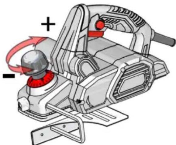
Brushing depth adjustment
Fig. 5.
⚠ WARNING: Always switch off the product and disconnect it from the mains before making any adjustments.
- Set the desired depth by turning the Depth of Cut Adjustment Knob (9). Range 0 to 2 mm. The number on the Cutting Depth Scale (8) indicates the depth in millimetres.
Switching On/Off
Fig. 6.
- Press and hold the Lock button (2).
- Press the On/Off Switch (1) to turn on.
- Release the On/Off Switch (1) to turn off.
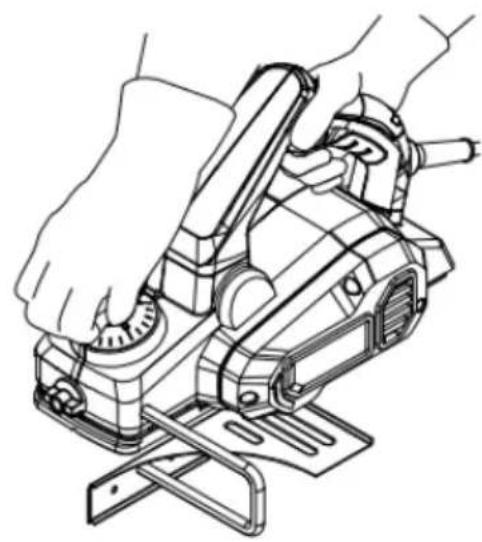
General brushing
Fig. 7


WARNING! Fine dust will be generated during operation.
These dusts are highly flammable and may explode. Do not smoke during operation and keep heat sources and open flames away from the work area.
Always wear a dust mask to protect yourself from the hazards of fine dust.
- Set the desired depth.
- Hold the Main Handle (3) with one hand and the Cutting Depth Adjustment Knob (9) with the other hand.
- Turn on and wait at full speed before resting on the workpiece.
WARNING! Danger of backlash! Apply the tool to the workpiece only when the power is on.
-
Rest the Front Plate (18) flat on the workpiece and move the product forward at a uniform speed, with light and constant pressure.
-
Turn the Depth of Cut Adjustment Knob (9) counterclockwise to retract the Blades when finished.

Recommendations:
- Perform a test pass after changing Blades or adjusting depth.
- For a high-quality finish: slow feed, light pressure in the centre of the base, shallow and repeated passes.
- On hardwoods or at maximum planing width, use shallow depths and reduce the feed rate.
- Excessive feed reduces surface quality and can obstruct chip ejection.
- Only sharp blades provide good performance and longer life.
ENGLISH
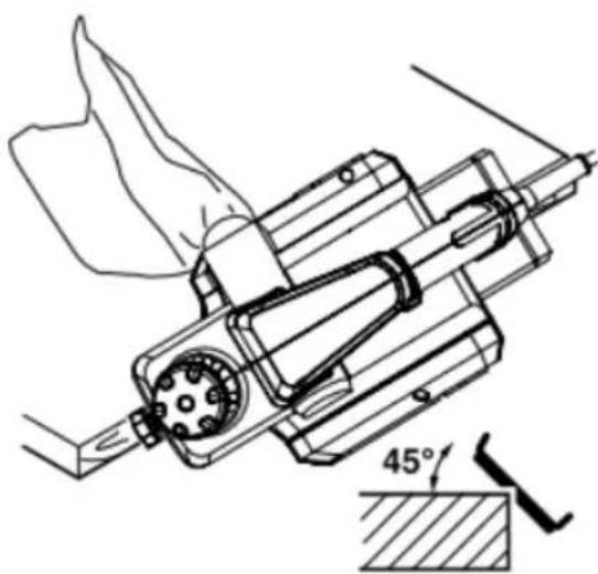
Bevel-planned
Fig. 8
With the V-Slot (17) you can make 45^ chamfers on the edge of the workpiece:
- Place the V-Slot (17) over the edge and apply light, steady pressure.
- Guide the product along the edge.
After use
- Switch off, wait for complete stop, disconnect from the mains and allow to cool.
- Check, clean and store as indicated below.
WARNING!


Always switch off the product, disconnect it from the mains and allow it to cool down before carrying out inspection, maintenance or cleaning work.
Only perform the care and maintenance operations described in these instructions.
Any other work must be performed by qualified personnel.
5. CLEANING AND MAINTENANCE
General cleaning
- Clean with a dry cloth. Use a brush in hard-to-reach areas.
- After each use, clean the roller (14), blade (12), switches and vents.
- Remove stubborn dirt with pressurized air (max. 3 bar).
- Check for worn or damaged parts. Replace if necessary or contact the Cecotec's Official Technical Support Service.
NOTE: Do not use chemical detergents, alkalis, abrasives or other harsh cleaners or disinfectants to clean this product, as they may damage its surfaces.
Dust extraction outlet
Unclog and clean the dust extraction outlet (10) with a suitable tool (e.g. a lath) or compressed air.

WARNING! Do not insert bare fingers into the outlet. Do not place any finger or other body t in the dust extraction outlet (10). Always unclog the dust extraction outlet (10) with a able tool, such as a wooden stick.
Maintenance
Before and after each use, check the product and its accessories (or couplings) for wear or damage. If necessary, replace them with new elements following the procedures described in this instruction manual.
Replacing the blades
Fig. 9 and 10
- Place the product on a flat surface with access to the base.
- Rotate the roller (14) until the Blade shaft is positioned between the front plate (18) and rear plate (13).
- Turn the hexagonal screws (11) with the wrench (20) in order to remove the blade holder (15) from the Roller (14) (Fig. 9).
- Move the blade (12) sideways by gently tapping it with a suitable tool and remove it with e.g. pliers (Fig. 10).
- Rotate the roller (14) 180^ and repeat for the other Blade (12).
- Carefully clean all parts.
NOTE: Generally, planing knives can be used on both sides. For the first replacement, rotate the blade vertically 180^ and reassemble. If both sides of a blade are worn, replace it with a new pair of blades.
- Insert the new blade sideways into the slot in the Blade Holder (15), with the bevel facing the Back Plate (13). Ensure correct orientation and centering.
- Insert the Blade Holder (15) into the Roller (14) and check that the Blade is flush with the side edge of the Back Plate (13). Tighten the hex screws (11) until the assembly is securely fastened.
- Repeat for the second blade (12).
- Rotate the roller with the help of a ribbon to confirm that the Blade does not contact the Front Plate or Back Plate. Adjust if necessary.
Blade holder adjustment
Fig. 11
The blade holder (15) is factory preset for uniform planing with original blades; it does not normally require readjustment. However, occasionally check that the cutting edges are parallel and coplanar with the Back Plate (13). If necessary, adjust the height with the Allen key (21):
- Loosen the hex screws (11).
- Turn the set screws (16) clockwise to increase the height.
- Turn the set screws (16) counterclockwise to decrease the height.
- Tighten the hex screws (11).
Transport
WARNING! Always transport the product by holding the main handle (3). Never use the cable to transport the product.
- Switch off and disconnect from the mains.
- Protect the product against strong impacts or vibrations during transport.
ENGLISH
- Secure the product to prevent slipping or falling.
Storage
- Switch off and disconnect from the mains.
- Clean as indicated.
- Store the product and accessories in a dark, dry, frost-free and well-ventilated place.
- Keep out of the reach of children. Ideal storage temperature: 10^ C - 30^ C.
- You can use the original packaging or cover with a suitable dust cover.
6. TROUBLESHOOTING
Some failures are due to causes that can be solved by the user himself. Therefore, please review the product using this section. In most cases, the problem can be solved quickly.

WARNING!
- Only perform the steps described in these instructions.
- Any additional inspection, maintenance or repair should be performed by an authorized service technician or qualified specialist if you are unable to solve the problem yourself.
Note: Perform all checks with the product switched off, disconnected and at complete stop.
| Problem Possible cause | Solution | |
| Product will not start. | Not connected to the mains. Connect it to the mains | |
| The power cord or plug is faulty. Must be inspected by a qualified electrician/specialist. | ||
| Product does not reach full power. | The extension cord is not suitable for this product. | Use a suitable extension cord. |
| Power supply (e.g. generator) voltage too low. | Connect to another power supply. | |
| The ventilation grids are obstructed. | Clean the ventilation grilles. | |
| Unsatisfactory result. | The blade (12) is blunt/damaged. Replace with a new one. | |
| Excessive advance causes poor surface quality. | Reduce the advance. | |
| The working pressure is not applied in the centre of the brush base. | Adjust the position to apply the correct pressure. | |
| Excessive vibration or noise. | The blade (12) is blunt/damaged. | Replace with a new one. |
| Loose screws/nuts. Tightening bolts/nuts. | ||
| Blade not mounted in parallel. Mount/adjust the blades (12) in parallel. | ||
| The motor runs, but the roller (14) does not rotate or stops. | Worn or broken drive belt. Replace it with a new one by contacting Cecotec's Official Technical Support Service. | |
7. RECYCLING OF ELECTRICAL AND ELECTRONIC EQUIPMENT
This symbol indicates that, according to the applicable regulations, the product and/or battery must be disposed of separately from household waste. When this product reaches the end of its shelf life, you should dispose of the batteries/accumulators and take them to a collection point designated by the local authorities.
For detailed information on how to properly dispose of electrical and electronic equipment and/or the corresponding batteries, consumers should contact their local authorities.
Information regarding national packaging recycling systems and their marking can be found on our website.
Compliance with the above guidelines will help protecting the environment.
8. COPYRIGHT
The intellectual property rights over the texts in this manual belong to CECOTEC INNOVACIONES, S.L. All rights reserved. The content of this publication may not, either in part or in its entirety, be reproduced, stored in a retrieval system, transmitted or distributed by any means (electronic, mechanical, photocopying, recording or similar) without prior authorisation from CECOTEC INNOVACIONES, S.L.
EU01_117915 - Fast&Clean 3000 Agile
9. DECLARATION OF CONFORMITY
MANUFACTURER: CECOTEC INNOVACIONES S.L
ADDRESS: Av. Reyes Católicos, 60, 46910, Alfafar, Valencia (Spain)
DESCRIPTION: Electric planer
ENGLISH
PRODUCT IDENTIFICATION: Fast&Clean 3000 Agile
FUNCTION: Electric wood planer
MODEL: EU01_117915
It certifies that the product described has been designed, manufactured and tested and complies with all applicable requirements.
EU DIRECTIVES IMPLEMENTED:
- Directive 2006/42/CE on machinery.
- Directive 2014/30/EU on the harmonisation of the laws of the Member States relating to electromagnetic compatibility.
- Directive 2011/65/EU and delegated directive (EU) 2015/863 on the restriction of the use of certain hazardous substances in electrical and electronic equipment.
APPLICABLE HARMONISED NORMS:
- EN 62841-1:2015 +A11:2022
- EN 62841-2-14:2015
- EN IEC 55014-1:2021
- EN IEC 55014-2:2021
- EN IEC 61000-3-2: 2019+A1
- EN 61000-3-3:2013+A1+A2
- IEC 62321-3-1:2013; IEC 62321-4:2013+A1:2017; IEC 62321-5:2013; IEC 62321-6:2015; IEC 62321-7-1:2015; IEC 62321-7-2:2017; IEC 62321-8:2017, EN ISO 17075-1:2017
1. PIÈCES ET COMPOSANTS
Image
6. PROBLEEMOPLOSSING
Fig./Img./Abb./Afb./Rys.1
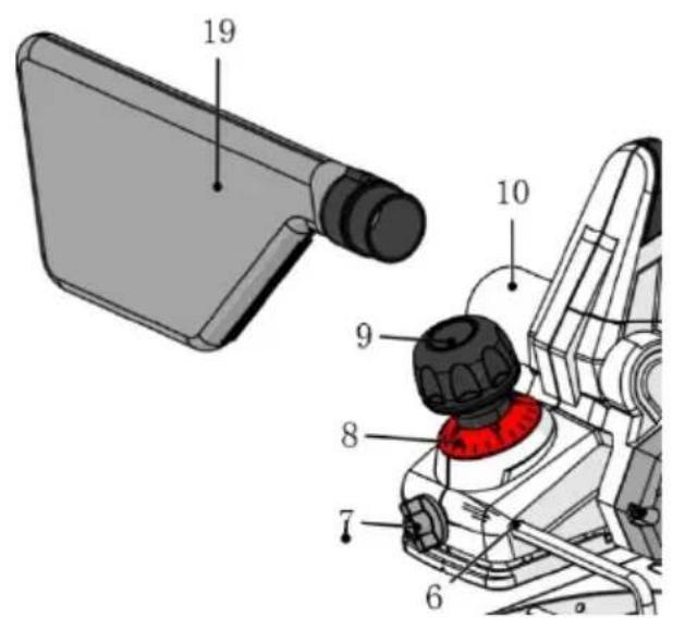
Fig./Img./Abb./Afb./Rys.2
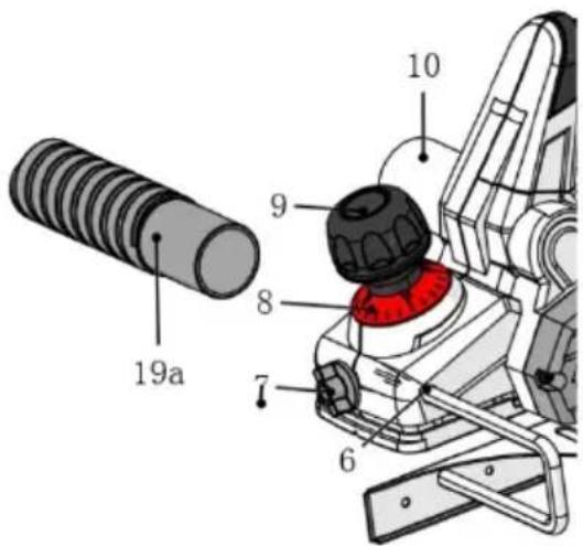
Fig./Img./Abb./Afb./Rys. 3
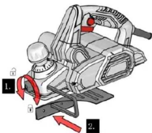
Fig./Img./Abb./Afb./Rys. 4
natural_image
Illustration of a mechanical power saw with red-handled joints and motion arrows (no text or symbols)Fig./Img./Abb./Afb./Rys. 5
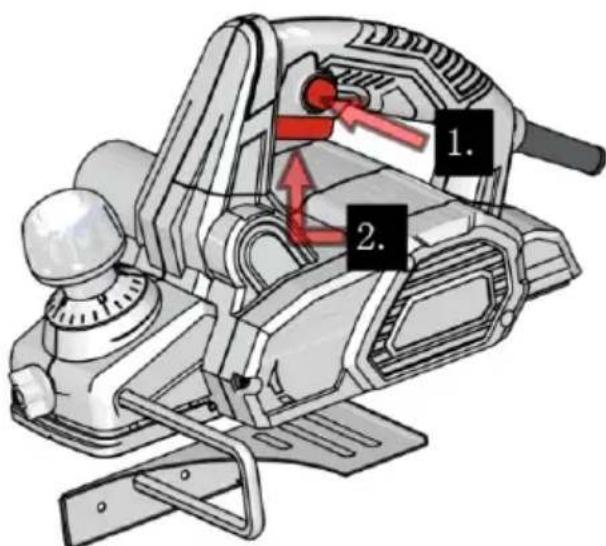
Fig./Img./Abb./Afb./Rys. 6
natural_image
Line drawing of hands operating a power saw on an electrical machine (no text or symbols)Fig./Img./Abb./Afb./Rys. 7
natural_image
Technical line drawing of a mechanical assembly with a 45-degree angle标注 (no text or symbols beyond the angle marker)Fig./Img./Abb./Afb./Rys. 8
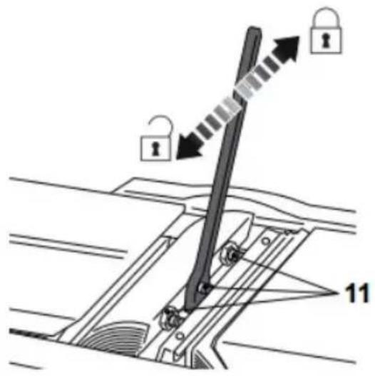
Fig./Img./Abb./Afb./Rys. 9
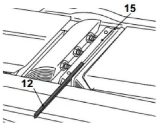
Fig./Img./Abb./Afb./Rys. 10
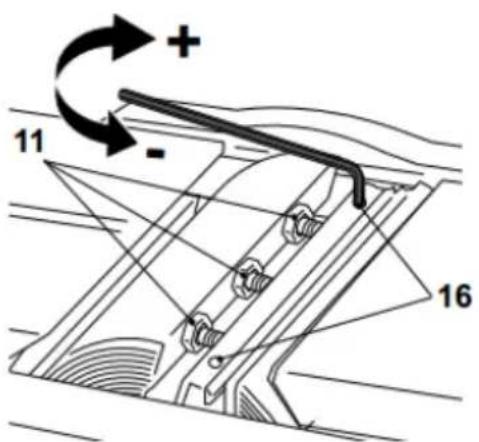
Fig./Img./Abb./Afb./Rys. 11
www.cecotec.es

- INDEX
- SOMMAIRE
- General power tool safety instructions
- Work area safety
- Electrical safety
- Personal safety
- Power tool use and maintenance
- Service
- Safety warnings specific to brushes
- INSTRUCTIONS DE SÉCURITÉ
- Note:
- BEFORE USE
- Box content:
- INSTALLATION
- Unpacking
- WARNING!
- WARNING
- Dust extraction
- ENGLISH
- Chip and dust collection bag
- Emptying
- External vacuuming
- Parallel guide
- OPERATION
- Usage instructions
- Before starting
- Brushing depth adjustment
- Switching On/Off
- General brushing
- Bevel-planned
- CLEANING AND MAINTENANCE
- General cleaning
- Dust extraction outlet
- Maintenance
- Replacing the blades
- Fig. 9 and 10
- Blade holder adjustment
- Fig. 11
- Transport
- Storage
- TROUBLESHOOTING
- RECYCLING OF ELECTRICAL AND ELECTRONIC EQUIPMENT
- COPYRIGHT
- DECLARATION OF CONFORMITY
- EU DIRECTIVES IMPLEMENTED:
- APPLICABLE HARMONISED NORMS:
- PIÈCES ET COMPOSANTS
- Image
- PROBLEEMOPLOSSING
Brand : CECOTEC
Model : Fast&Clean 3000 Agile
Category : Plane