330020 - Barbecue Browin - Free user manual and instructions
Find the device manual for free 330020 Browin in PDF.

| Product type | Portable electric smoker |
| Brand | Browin |
| Model | 330020 |
| Main material | Stainless steel |
| Power | 1100 W |
| Voltage / Frequency | 220-240 V / 50 Hz |
| Power cord length | 170 cm |
| Body dimensions (diameter x length) | 25 cm x 45 cm |
| Total length including handle | 65 cm |
| Height between grate and top wall | 13.5 cm |
| Weight | 5.2 kg |
| Thermometer range | 0-250 °C |
| Temperature control | Built-in thermostat |
| Main functions | Smoking and roasting foods (poultry, meat, fish) |
| Included accessories | Grate, drip tray, chip tray, stand, thermometer, cable with thermostat, heating cover, feet, wooden handles, screws and nuts |
| Usage | Outdoor only with wood chips; indoor use allowed without chips (as an oven) |
| Maintenance and cleaning | Unplug and let cool; remove used chips and clean trays and grates |
| Safety | Wearing protective gloves recommended; hot metal surfaces; do not use indoors with chips |
| Spare parts and repairability | Standard parts (grate, tray, thermometer, etc.); repair by a professional if needed |
| General information | User manual available in multiple languages |
Frequently Asked Questions - 330020 Browin
User questions about 330020 Browin
0 question about this device. Answer the ones you know or ask your own.
Ask a new question about this device
Download the instructions for your Barbecue in PDF format for free! Find your manual 330020 - Browin and take your electronic device back in hand. On this page are published all the documents necessary for the use of your device. 330020 by Browin.
USER MANUAL 330020 Browin
This versatile electric smoker made of stainless steel allows roasting combined with the option to give dishes the smoked aroma. It allows quick and easy smoking of poultry and any other favourite types of meat or fish.
The device is powered by a built-in heater with power of 1100 W, featuring a thermostat that enables temperature adjustment. The smoker body features a thermometer that enables monitoring temperature during the whole smoking or roasting process.
The wooden handle of the smoker enables moving it around or opening it at any moment during the process.
The oak holder included enables convenient and safe removal of the hot wood chip tray or product tray. Meanwhile, the drip tray will collect the fat dripping from the food prepared, preventing soiling of wood chips and heaters, which will make it easier to keep the smoker clean.
NOTE!
When the wood chips for smoking are used, the product can be only used outdoors in view of the smoke generated from burning chips. Indoor use is allowed only if the device is used as an oven, without burning wood chips.
NOTE! When handling the smoker, it is best to use protective gloves or kitchen gloves, as the metal parts will be very hot.
Please familiarise yourself thoroughly with this manual prior to using the device and keep it for future reference.
The set includes:
1. The set includes:
| Name | Quantity | Picture |
| Smoker housing with the electric heater | 1 complete set | 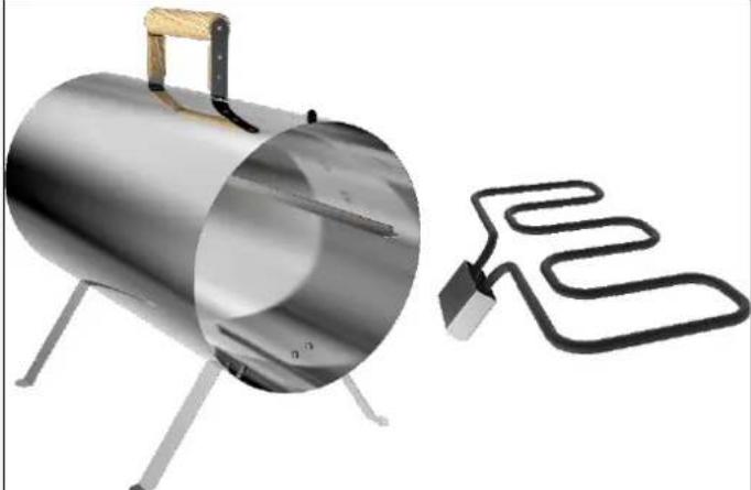 |
| Smoker cover | 1 pc. | 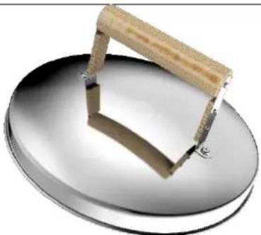 |
| Wooden handle | 2 pcs | 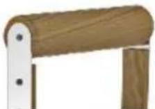 |
| Steel feet | 4 pcs | 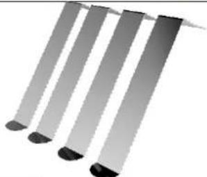 |
| Power supply cable with thermostat | 1 pc. | 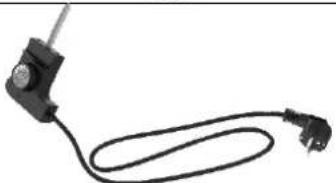 |
| Heater shield | 1 pc. | 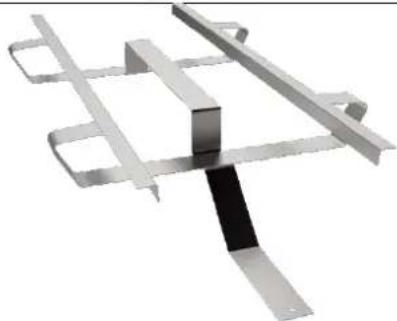 |
| Grill | 1 pc. | 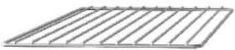 |
| Drip tray | 1 pc. | 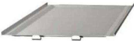 |
| Wood chip tray | 1 pc. | 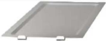 |
| Holder | 1 pc. | 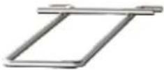 |
| Thermometer | 1 pc. |  |
| M5x9 bolts | 15 pieces | 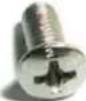 |
| M5 nuts | 15 pieces |  |
| Manual | 1 pc. |  |
Technical data:
• Power: 1100 W
• Voltage: 220V-240V
• Frequency: 50 Hz
• Power supply cable 170 cm
- Thermometer in the cover, with temperature range of 0-250 °C
• Temperature control unit
• Material: stainless steel
• Body diameter: 25 cm
• Body length: 45 cm
• Total length with handle: 65 cm
- Weight: 5.2 kg
• Height between the grill and the upper wall: 13.5 cm
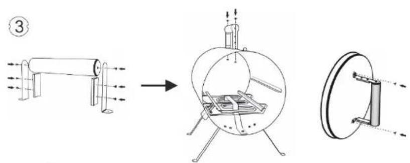
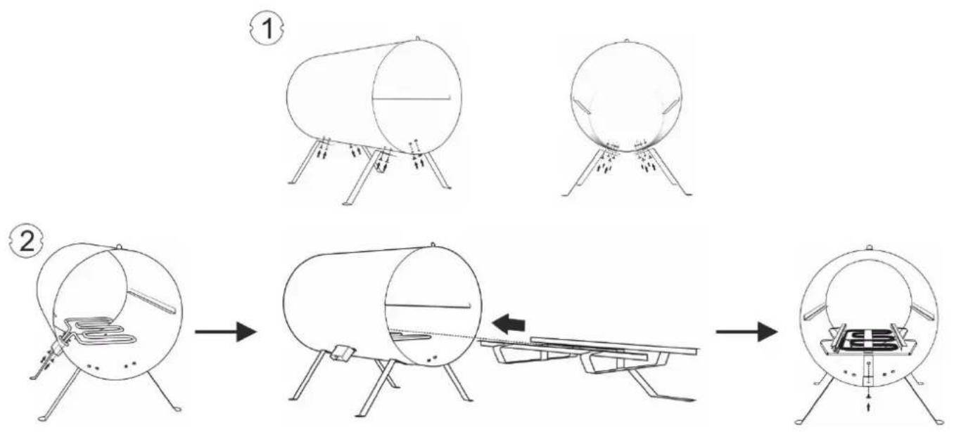
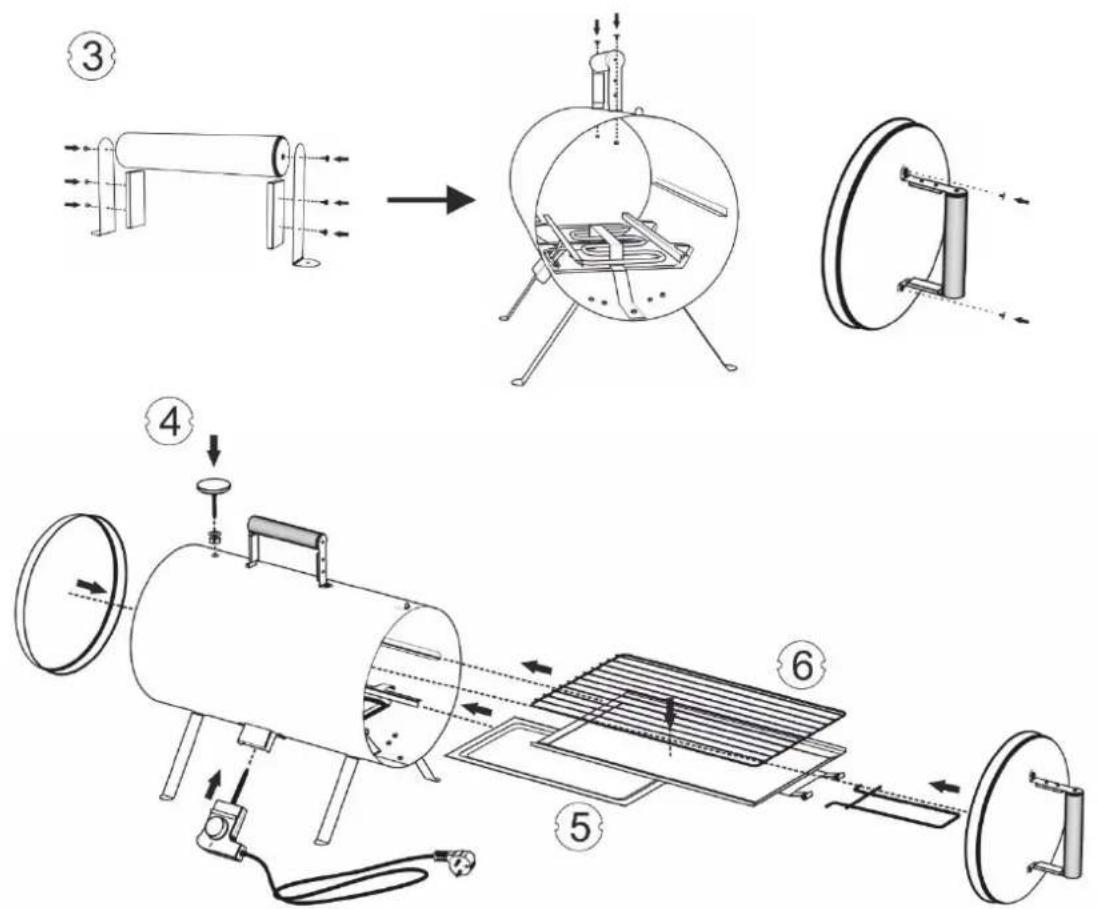
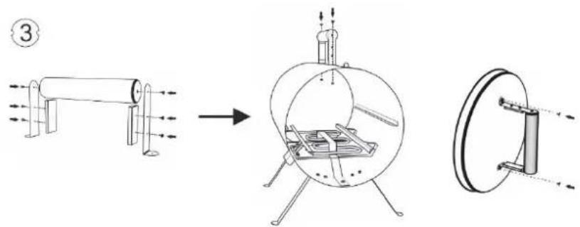
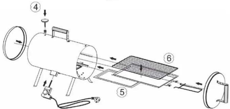
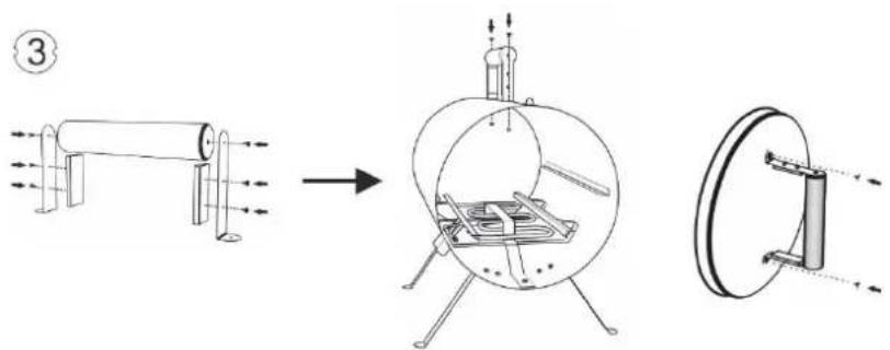
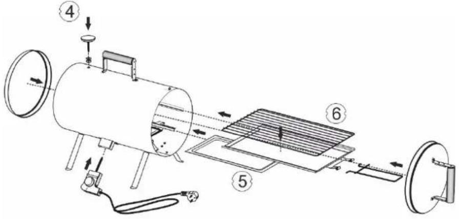
2. Assembly
Assemble the device on a clean and flat surface.
Tools needed: cross head screwdriver and wrench No. 8.
- Screw the feet to the smoker body using 8 bolts (used two bolts for each foot). Put the bolt into the right hole from the outside and twist a nut onto the thread from the inside.
- Slide the heater into the smoker chamber and screw it to the body in the side part between the feet using two bolts and two nuts. Next, installed the shield on the heater and screw it to the bottom edge of the body using a bolt and a nut.
- Screw the wooden holders in place (one in the upper part of the body, the other to the smoker cover) using bolts. Insert them from the outside of the body and the cover and twist a nut onto each of them from the inside of the chamber and the cover.
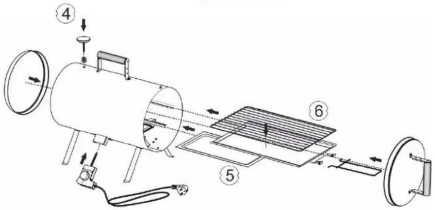
-
Install the thermometer in the upper part of the body, in a dedicated opening, by screwing it in place from the inside of the chamber.
-
Place the wood chip tray on the heater shield, directly over it.
- Place the drip tray and the grill on the guides attached permanently to the internal walls of the smoker.
flowchart
graph TD
    A["Step 1: Initial tank setup"] --> B["Step 2: Round-bottom tank with internal components"]
    B --> C["Step 3: Round-bottom tank with horizontal structure and table setup"]
    C --> D["Step 4: Final assembled tank with internal components"]
HOW TO USE
Familiarising yourself thoroughly with the recommendations below will enable using the smoker properly and enjoy its faultless functioning for a long time.
However, in order to achieve fully satisfying effects it is necessary to always adhere to several fundamental recommendations when using it.
-
Start the preparations for the smoking process by placing the smoker outdoors, on a stable, heat-resistant surface. Choose a place sheltered against rain but ensuring good air circulation.
-
After assembling the smoker, it is necessary to "fire" it prior to first smoking. This process should take about 20 minutes and it is carried out in order to burn any remains from production stage. "Firing" should be carried out according to the procedure below:
a. DO NOT carry out the "firing" process indoors. This process HAS TO be carried out outdoors.
b. During the "firing" process use only temperature - DO NOT use any wood chips.
c. Connect the power supply cable and turn the knob on the thermostat clockwise, to the limit.
d. Wait 20 minutes for the device to warm up and then turn the power supply off.
-
Remember to dry the meat very carefully prior to commencing smoking. Poorly dried products may cause humidity to accumulate inside the chamber during smoking and lead to faulty processing of smoked meat. The product drying can also be finished in the smoker chamber with the thermostat set to the minimum, without closing the smoker.
-
Place the wood chips on the tray directly over the heat, in the amount of about 60 g - three handfuls. However, it is necessary to take not to use an excessive amount as it may have adverse impact on the flavour of food smoked (the meat may acquire a sour aftertaste). The amount of wood chips used should be sufficient for about an hour of smoking. Remember that you can always add wood chips during the smoking process.
-
Place the grill on the drip tray and arrange on it the products intended for roasting or smoking.
-
Leave some free space between the products roasted on the grills and the sides of the smoker in order to ensure proper circulation of heat and smoke.
-
The wood chips start burning after achieving the right temperature, which takes place about 10-15 minutes after turning the device on. The temperature, starting time, and continuity of wood chip burning depends on the ambient temperature.
-
During the whole smoking process it is necessary to monitor the temperature inside the smoker using the smoking thermometer installed in the body of the device. The adjustment of temperature is carried out by means of a thermostat knob. In the event of the temperature in the chamber being too high it is possible to open the smoker cover slightly.
-
If the colour of the products smoked is already satisfactory, but the product requires further thermal processing, continue the process without adding wood chips.
-
For removing the grill and the trays, use the holder intended for that purpose.
-
After completing the process, disconnect the power supply cable. Wait for the device to cool before removing spent wood chips and any staining that appeared.
flowchart
graph TD
    A["Step ①: Initial cylindrical tank"] --> B["Step ②: Initial cylindrical tank with internal components"]
    B --> C["Step ③: After assembly of a flat surface on a table"]
    C --> D["Step ④: Final assembled cylindrical tank with internal components"]
BENUTZUNGSWEISE:
flowchart
graph TD
    A["①: Heating Tank"] --> B["②: Ventilation Room"]
    B --> C["③: Ventilation Panel"]
    C --> D["④: Air Fan with Sensor"]
    D --> E["⑤: Storage System with Heat Exchanger"]
    E --> F["⑥: Ventilation Panel with Refrigerator"]
СПОСОБ ЭКСПЛУАТАЦИИ
flowchart
graph TD
    A["1: Round Tub with Ventor"] --> B["2: Circular Bottle with Bed"]
    B --> C["3: Box on table with Lamp"]
    C --> D["4: Tower with Box"]
NAUDOJIMO BÜDAS
flowchart
graph TD
    A["Step ①: Folding cylinder tank"] --> B["Step ②: Folding cylinder tank with attached chair"]
    B --> C["Step ③: Mounting table with base"]
    C --> D["Step ④: Cover or installed container"]


LIETOŠANAS VEIDS
flowchart
graph TD
    A["①: Heating Tank"] --> B["②: Ventilation Room"]
    B --> C["③: Ventilation Tower"]
    C --> D["④: Air Fan with Sensor"]
    D --> E["⑤: Storage System with Panel"]
    E --> F["⑥: Ventilation Panel with Panel"]
KASUTAMISVIIS
flowchart
graph TD
    A["①: Heating Tank"] --> B["②: Ventilation Room"]
    B --> C["③: Ventilation Panel"]
    C --> D["④: Air Fan with Sensor"]
    D --> E["⑤: Storage System with Heat Exchanger"]
    E --> F["⑥: Ventilation Panel with Refrigerator"]
MOD DE UTILIZARE
flowchart
graph TD
    A["Step 1: Heating furnace with cylindrical tank"] --> B["Step 2: Ventilation device with internal components"]
    B --> C["Step 3: Ventilation device with air vent and fan assembly"]
    C --> D["Step 4: Storage tank with internal equipment"]
    D --> E["Step 5: Refrigeration unit with solar panel and gas stove"]
    E --> F["Step 6: Storage tank with internal equipment"]
POUŽÍVÁNÍ
flowchart
graph TD
    A["Stage ①: Cylinder with vertical supports"] --> B["Stage ②: Circular tank with horizontal arm"]
    B --> C["Stage ③: Box on table with base"]
    style A fill:#f9f,stroke:#333
    style B fill:#ccf,stroke:#333
    style C fill:#cfc,stroke:#333


NÁVOD NA POUŽITIE
flowchart
graph TD
    A["①: Heating Tank"] --> B["②: Ventilation Room"]
    B --> C["③: Ventilation Panel"]
    C --> D["④: Air Fan with Sensor"]
    D --> E["⑤: Storage System with Heat Exchanger"]
    E --> F["⑥: Ventilation Panel with Solar Panel"]
MODE D'EMPLOI
flowchart
graph TD
    A["①: Heating Tank"] --> B["②: Ventilation Room"]
    B --> C["③: Ventilation Panel"]
    C --> D["④: Air Fan with Sensor"]
    D --> E["⑤: Storage System with Heat Exchanger"]
    E --> F["⑥: Ventilation Panel with Refrigerator"]
СПОСІБ ВИКОРИСТАННЯ
flowchart
graph TD
    A["Step ①: Folding cylinder tank"] --> B["Step ②: Folding cylinder tank with attached chair"]
    B --> C["Step ③: Mounting table with base"]
    C --> D["Step ④: Mounting table with battery"]