DDF2120400 - Screwdriver DEWALT - Free user manual and instructions
Find the device manual for free DDF2120400 DEWALT in PDF.

| Product type | Powder-actuated tool (powder nailer) |
| Brand | DeWalt |
| Model | DDF2120400 (PA3500) |
| Length | 340 mm |
| Weight | 2.35 kg |
| Power source | Cartridge strips cal. .27 (6.8/11), 10 cartridges per strip |
| Firing power | 3 loads (green, yellow, red), 6 adjustment levels |
| Firing frequency | Up to 500 nails per hour |
| Nail type | Headed nails, diameter 7.6 mm, max length 63 mm (without pre-drilling) or 76 mm (with pre-drilling) |
| Sound pressure level | L_pA 99 dB(A) (measurement area), 104 dB(A) (workplace) |
| Vibration level | < 2.5 m/s² |
| Base materials | Normal strength concrete, steel, masonry (min. thickness 10 cm) |
| Supplied equipment | Powder-actuated tool, manual, round brush 3-piece, nylon brush, hex key 5 mm, splash guard, pliers, steel balls |
| Safety instructions | Wear goggles, helmet, hearing protection; keep hands away from barrel; daily function test |
| Maintenance | Cleaning after each use, disassembly and cleaning of internal parts, piston lubrication |
| Repairability | Repairs only at authorized specialized workshop |
| Warranty | 1 year for material or manufacturing defects |
| Standards | Machinery Directive 2006/42/EC, EN 15895, CIP PTB S 824 approval |
Frequently Asked Questions - DDF2120400 DEWALT
User questions about DDF2120400 DEWALT
0 question about this device. Answer the ones you know or ask your own.
Ask a new question about this device
Download the instructions for your Screwdriver in PDF format for free! Find your manual DDF2120400 - DEWALT and take your electronic device back in hand. On this page are published all the documents necessary for the use of your device. DDF2120400 by DEWALT.
USER MANUAL DDF2120400 DEWALT
natural_image
Exterior view of a white and black DeWALT handheld tool (no text or symbols on body)DDF2120400
English (Translation of the original instructions) 31
Personbeskyttelse:
Stål:
Stålet skal have en tykkelse på mindst 3 mm.
3.3 Daglig funktionstest
natural_image
Diagram of a handheld electric tool with an arrow indicating motion direction (no text or symbols)4 Händtering

ADVARSEL
natural_image
Line drawing of a hand holding a mechanical component with an arrow indicating direction (no text or symbols)natural_image
Illustration of a hand using a tool to adjust or install a screwdriver, with an inset showing the tool's rotation (no text or symbols present)natural_image
Illustration of a hand using a tool to cut a mechanical component, with an inset showing a close-up of the component (no text or symbols present)natural_image
Illustration of a hand holding a mechanical component with an inset showing a close-up of a tool interacting with it (no text or symbols present)natural_image
Technical illustration of a handheld device with an inset close-up showing a 3D model (no text or symbols present)natural_image
Illustration of hands assembling a mechanical component with an arrow indicating motion (no text or symbols)natural_image
Line drawing of hands using a tool to adjust or install a component, with an inset showing a close-up of the tool (no text or symbols present)Fjern kolben.
natural_image
Line drawing of a hand holding a mechanical component with an arrow indicating direction (no text or symbols)natural_image
Illustration of a syringe being inserted into a bulb with a magnified view showing the bulb (no text or symbols)natural_image
Line drawing of a mechanical component with an arrow indicating direction (no text or symbols)natural_image
Illustration of a hand holding a pen or tool with an arrow indicating direction (no text or symbols present)natural_image
Illustration of a hand holding a mechanical component with two arrows indicating assembly or adjustment (no text or symbols present)natural_image
Diagram of a handheld device with an inset showing a close-up view of a mechanical component (no text or symbols present)→Sæt stålkuglen i.
natural_image
Line drawing of a hand holding a cylindrical mechanical component with an arrow pointing to it (no text or symbols present)Stahl:
natural_image
Diagram of a handheld electric drill bit with an arrow indicating motion direction (no text or symbols)4 Handhabung

WARNUNG
natural_image
Line drawing of a hand holding a tool with an arrow indicating direction (no text or symbols)natural_image
Illustration of a hand using a power tool to adjust or install a screwdriver, with an inset showing the tool's internal mechanism (no text or symbols present)natural_image
Illustration of a hand using a tool to cut a mechanical component, with an inset showing a close-up of the component (no text or symbols present)natural_image
Illustration of a hand holding a mechanical component with an inset showing a close-up of a tool inserted into a cylindrical part (no text or symbols present)natural_image
Diagram of a handheld tool with an inset close-up showing a 3D block structure (no text or symbols)natural_image
Illustration of hands connecting a mechanical component to a shaft, with an arrow indicating direction (no text or symbols present)natural_image
Illustration of hands using a tool to adjust or install a component, with an inset showing a magnified view of the tool (no text or symbols present)→Kolben entnehmen.
natural_image
Line drawing of a hand holding a mechanical component with an arrow indicating direction (no text or symbols)natural_image
Line drawing of a mechanical component with an arrow indicating direction (no text or symbols)natural_image
Illustration of hands holding a cylindrical device with an arrow indicating direction (no text or symbols)natural_image
Line drawing of a hand holding a mechanical component with two arrows indicating direction (no text or symbols)natural_image
Diagram of a handheld device with an inset showing a close-up of its internal structure (no text or symbols present)natural_image
Illustration of a hand holding a cylindrical mechanical component with an arrow pointing to it (no text or symbols present)Construction and DIY Europe
D-65510, Idstein, Germany
10 C.I.P. Zulassung
1.1 Intended use 32
1.2 Safety labels on the device 32
1.3 Warnings in this manual ....33
1.4 Protective equipment 33
1.5 Device and operational safety ....33
1.6 Disposal 34
2 Scope of delivery and accessories ....35
2.1 Scope of delivery 35
2.2 Cartridge strips....35
2.3 Shooting nails 35
3 Before using the device....35
3.1 Minimum distances while shooting nails 35
3.2 Minimum thicknesses of the subsurfaces .....36
3.3 Daily functions test .... 36
3.4 Test attachment....36
4 Handling....37
4.1 Inserting the shooting nail 37
4.2 Inserting and removing the cartridge strip 37
4.3 Firing the shooting nails 38
5 Inspection and cleaning ....38
5.1 Disassembling the powder actuated tool 38
5.2 Checking and cleaning the interior parts of the device 39
5.3 Assembling the powder actuated tool ....40
5.4 Cleaning the device surfaces 40
6 Technical data 41
7 Troubleshooting....41
8 Manufacturer warranty 43
9 Declaration of conformity....43
10 C.I.P. approval confirmation....44
1 Safety notes

Please read the safety information carefully in order to ensure a safe and proper operation of the device. Retain the operating instructions until the product is disposed of.
1.1 Intended use
The Power Actuated Tools are intended for setting nails and must be used according to the information in this user manual. Powder Actuated Tools are not "toys" and require prudent, responsible and careful handling.
Powder Actuated Tools are intended for professional use and are subject to certain legal provisions.
Responsibilities of the employer, for example:
- Manufacturer's recommended intervals for routine inspection and maintenance: every 2 years, but no later than every 3,000 settings, unless shorter intervals are prescribed by law.
– Repairs must be made at authorized technical facilities.
– Collection and safe disposal of "misfi red cartridge" - Safe storage of the Power Actuated Tools (unloaded) in the locked tool box a the cartridge strips (separately from each other).
- Provisioning and ensuring the usage of protective equipment, see chapter 1.4 "Protective equipment"
The stud gun is to be operated only by trained personnel over 18 years old, or by trainees over 16 years old in the presence of a supervisor.
The operator must not be fatigued or under the influence of alcohol, medication or drugs.
Suitable materials to use as a base, for example
– Concrete of normal strength
- S t e e l
Materials that are unsuitable and should not be used as a base, for example:
– Materials that are too soft or too thin
– Materials that are too brittle, such as glass or ceramic
– Materials that are too hard, such as hardened steel
– Hollow block masonry, perforated brick masonry
– Cast iron, plastic, marble, gypsum plasterboards
Misapplications, misuse or "fooling around" may cause lethal injuries and serious property damage. This particularly includes
– The overriding of safety mechanisms
- Misusing the device as a "fi rearm"
– Misusing the device as a hammer or similar tool
- Never use the cartridge strips in firearms or attempt to open them.
You may only use cartridge strips, shooting nails and accessories produced by the Powder Actuated Tool manufacturer, see chapter 2.2 "Cartridge strips" and chapter 2.3 "Shooting nails".
Other applications and uses as well as modifications to the device, additions to the device or conversions as well as maintenance operations and repairs performed by yourself can impair the safety, reliability and proper functioning of the device to a significant extent and void any warranty claims.
1.2 Safety labels on the device
The device may only be used if all safety labels on the Powder Actuated Tool are both complete and legible.

Read the instruction manual prior to using the device

Wear safety goggles

Wear hearing protection

Wear a safety helmet
1.3 Warnings in this manual
The risk level associated with particular hazards is identified by signal words:
| Signal word | Meaning |
| DANGER | Hazard with a high level of risk, which will result in death or a serious injury, if not avoided |
| WARNING | Hazard with a medium level of risk, which can result in death or a serious injury, if not avoided. |
| CAUTION | Hazard with a low level of risk, which can result in minor or moderate injuries, if not avoided. |
| NOTICE | Hazard, which may lead to the device or equipment in the vicinity to be damaged, if not avoided. |
1.4 Protective equipment
Loose clothes, jewellery, falling objects, noise and similar hazards may present a danger to persons. Persons that will be using the device and have to reside in the vicinity of the device, must wear suitable personal safety equipment:

Suitable safety helmet: protects the head against falling objects

Safety goggles: protects the eyes against fl ying objects, such as splinters and dust

Hearing protection: protects the ears against excessive noise

Suitable face protector: Protects eyes and face from fl ying objects, such as splinters.
1.5 Device and operational safety
Powder Actuated Tools can cause serious injuries if improperly handled.
- Danger of explosion: Never open or damage cartridge strips. Do not throw the strips into an open fire.
- Do not expose the Powder Actuated Tool and cartridge strips to high temperatures, for example the direct sunlight.
- Never place or store the Powder Actuated Tool and cartridge strips near heat sources, such as ovens or heaters.
- Only use the Powder Actuated Tool outdoors or in well ventilated areas.
- Keep Powder Actuated Tool (unloaded) in the locked tool case and the cartridge strips (separately from each other) safe from unauthorized access by adults and children.
- Only use the Powder Actuated Tool if it is in good working condition and has been properly maintained.
- When the device is not in use, the workplace is being changed, during transportation, in case of jams and during maintenance: Keep your finger away from the trigger, remove the magazine and cartridge strip.
- Slippery handles may lead to loss of control: Keep the handle dry, clean and free from oil and grease.
- There is a blowback/recoil when the shooting nail is fi red. Do not keep your head directly above the Powder Actuated Toll when fi ring the shooting nail and start with a low fi ring strength (power regulator) and charge, see chapter 2.2 "Cartridge strips" and chapter 3.4 "Test attachment".
- Ensure that you stand securely and can hold your balance, especially on platforms as well as elevated and/or slanted, uneven or slippery workplaces.
– The Powder Actuated Toll may not be used on a ladder. - The Powder Actuated Tool may not be used to close boxes or crates.
- The Powder Actuated Tool may not be used to fit transport locks to vehicles and wagons.
While being shot into the material, nails can break into multiple parts and cause serious injuries.
This can, for example, be the case if the fi ring strength is set too high. When fi ring nails into materials that are too soft, too thin or too hard. When nails strike other nails. When fi ring into pre-drilled holes without suitable guidance mechanisms.
- Keep a minimum distance to edges, borders and corners, see chapter 3.1 "Minimum distances while shooting nails".
- Keep a minimum distance of 75 ~mm to cracked or chipped areas of concrete.
- Determine the suitable fi ring strength (power regulator) and charge using a test attachment procedure, see chapter 3.4 "Test attachment".
- Use a splinter guard. This reduces the risks presented by ricocheting shooting nails
- You may not use the Powder Actuated Toll when people are located on the other side.
- Grab the Powder Actuated Tool firmly and hold it at a 90^ angle to the surface.
Protection of persons:
- Only insert the cartridge strip and shooting nail at the workstation in order to prevent an accidental fi ring, which may injure the user and/or bystanders.
– Never hold your hand or other body parts in front of the barrel.
– Never point the barrel at other persons. - Take a work break when feeling numb, extremely warm or cold or a tingling sensation in your fingers/arms. Consult a doctor if this phenomenon repeats.
Property damage:
- Do not fire nails into materials, which are welded or have been worked on with a welding torch.
- Do not use the Powder Actuated Tool or cartridge strips in the rain or a very humid environment.
- Only use the Powder Actuated Tool in well ventilated areas or outdoors.
- Do not use the Powder Actuated Tool with an empty magazine.
- Only store the Powder Actuated Tool and cartridge strips in dry and frost-protected rooms.
Immediately stop working:
– In case extreme heat is suddenly being generated.
- If screws or other parts have become loose or fallen off the device.
1.6 Disposal
NOTICE Unfi red cartridges (misfi red cartridge or duds) have to be collected and stored safely until they are disposed of by a specialist company. Observe the local regulations regarding disposal of technical equipment to protect the environment.
2 Scope of delivery and accessories
2.1 Scope of delivery
Check the scope of delivery after receipt of the Powder Actuated Tool. Report missing or damaged parts to your specialist dealer.
Scope of delivery:
– Powder Actuated Tool
- Instruction m
– Round brushes, 3 pieces, small, medium, large
- N y l o n b r u s h
- 5 mm hex key
- Splinter guard
– Clamps, 2 pieces (spare parts)
- Steel balls, 2 pieces (spare parts)
2.2 Cartridge strips
Cartridge strips with 10 cartridges each, .27 cal. (6.8/11), colour-coded according to charge/fi ring strength. Only the charge/fi ring strengths 3 (green), 4 (yellow) and 6 (red) of the device manufacturer are permitted for use with the PA3500 Powder Actuated Tool.
Art.No. Charge/Firing Strength
Only head nails with ballistically suitable tips produced by the device manufacturer are approved for use with the PA3500 Powder Actuated Tool.
Maximum length: 63 mm (without pre-drilling), 76 mm (with pre-drilling).
| Art.No. | mm | mm mm | pcs. | pcs. | ||
| a | n u a l | 16 | 7.6 | 3.7 | 100 | 5000 |
| DDF3010000 | ||||||
| DDF3000050 | 19 | 7.6 | 3.7 | 100 | 5000 | |
| DDF3000100 | 25 | 7.6 | 3.7 | 100 | 5000 | |
| DDF3000150 | 27 | 7.6 | 3.7 | 100 | 1000 | |
| DDF3000200 | 32 | 7.6 | 3.7 | 100 | 1000 | |
| DDF3000250 | 38 | 7.6 | 3.7 | 100 | 1000 | |
| DDF3000300 | 44 | 7.6 | 3.7 | 100 | 1000 | |
| DDF3000350 | 51 | 7.6 | 3.7 | 100 | 1000 | |
| DDF3000400 | 57 | 7.6 | 3.7 | 100 | 1000 | |
| DDF3000450 | 64 | 7.6 | 3.7 | 100 | 1000 | |
| DDF3000500 | 70 | 7.6 | 3.7 | 100 | 1000 | |
| DDF3000550 | 76 | 7.6 | 3.7 | 100 | 1000 | |
For additional accessories, please see the catalogue. Subject to change.
3 Before using the device
Observe the safety instructions, see chapter 1.5 "Device and operational safety".
3.1 Minimum distances while shooting nails
| Shooting nails | Masonry | Concrete, reinforced concrete | Steel |
| Distance to the edges | 5 cm | 5 cm | 3x Diameter of the nail shaft |
| Distance between each other | 10x Diameter of the nail shaft | 10x Diameter of the nail shaft | 5x Diameter of the nail shaft |
3.2 Minimum thicknesses of the subsurfaces
Masonry and concrete:
The thickness of the masonry or concrete must a least be equal to three times the penetration depth [L] of the shooting nail, but at least 10 cm in any case.
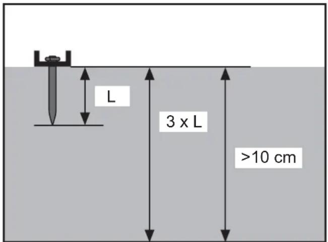
Steel:
The steel has to be at least 3 mm thick.
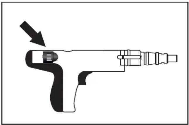
3.3 Daily functions test
The locking parts and the ignition mechanism have to operate in an unobstructed fashion and need to be inspected accordingly before using the Powder Actuated Tool.
- Ensure that there is no cartridge strip in the Powder Actuated Tool.
- Press the Powder Actuated Tool onto a work surface and pull the trigger several times.
Perform this test multiple times using the unloaded device and make sure that the locking parts and ignition mechanisms can move freely before attempting to perform any attachments using the device.
3.4 Test attachment

WARNING
Severe injuries in case of overpenetration of the shooting nail
→Perform a test attachment prior to commencing the actual work.
→Fully read the "Handling" chapter before attempting the test attachment, see chapter 4 "Handling".
→Perform the test attachment using the lowest fi ring strength (power regulator) and a “green” (3) charge.
→If the shooting nail does not penetrate far enough into the material: Gradually increase the fi ring strength (power regulator).
If the shooting nail does not penetrate deep enough into the material in spite of having set the highest fi ring strength: insert an cartridge strip with a higher charge strength and perform the test attachment again - using the lowest fi ring strength (power regulator).
natural_image
Diagram of a handheld electric tool with an arrow indicating motion direction (no text or symbols)4 Handling

WARNING
Serious injuries due to accidental triggering
Always keep the fingers away from the trigger if the Powder Actuated Tool is not facing the target material.
4.1 Inserting the shooting nail
NOTICE Do not force the shooting nail into the barrel. If the shooting nail cannot be inserted by hand, it may be damaged or be unsuitable for the Powder Actuated Tool, see chapter 2.3 "Shooting nails" and chapter 6 "Technical data".
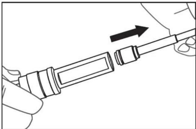
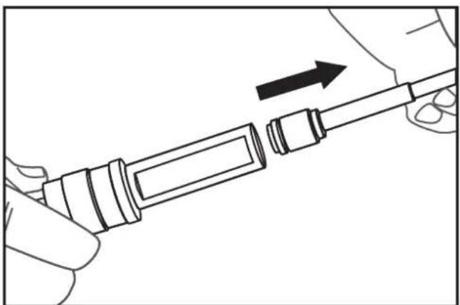
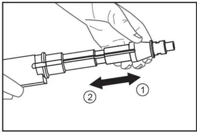
Insert the shooting nail into the barrel.
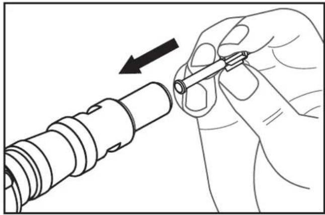
natural_image
Line drawing of a hand holding a mechanical component with an arrow indicating direction (no text or symbols)Pull the barrel all the way forward (1) in one firm motion and then pull it back to the stop (2).
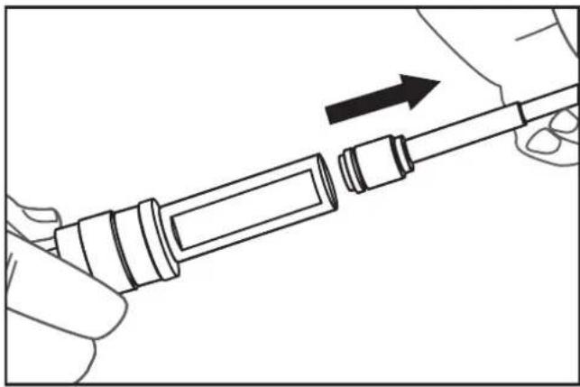
4.2 Inserting and removing the cartridge strip
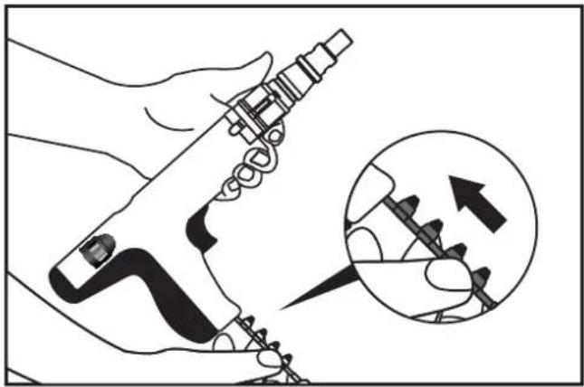
Inserting the cartridge strip
→Insert the cartridge strip tab fi rst into the underside of the grip until it sits fl ush.
natural_image
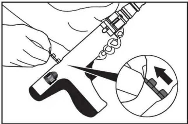
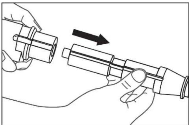
Illustration of a hand using a tool to adjust or install a mechanical component, with an inset showing the tool being inserted (no text or symbols present)Removing the cartridge strip:
→Grab the tab of the cartridge strip and pull the strip out of the Powder Actuated Tool from above.
natural_image
Illustration of a hand using a tool to cut a mechanical component, with an inset showing a close-up of the component (no text or symbols present)4.3 Firing the shooting nails

WARNING
Serious injuries due to accidental triggering
Always keep the fingers away from the trigger if the Powder Actuated Tool is not facing the target material.
→Determine the suitable fi ring strength (power regulator) and charge using a test attachment procedure, see chapter 3.4 „Test attachment“.
If the cartridge does not fi re immediately after pressing the trigger, keep the Powder Actuated Tool pressed against the target material for at least another 30 seconds.
For every workstation change: Remove the cartridge strip and carry the Powder Actuated Tool with the barrel pointing down.
After you fi nished working: fi rst remove the cartridge strip and then the shooting nail. Keep the Powder Actuated Tool stored in the locked tool box and store the cartridge strips in a safe place – both components separately from each other.
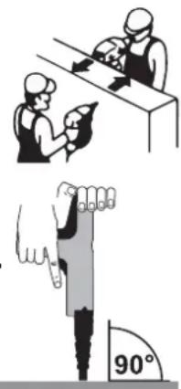
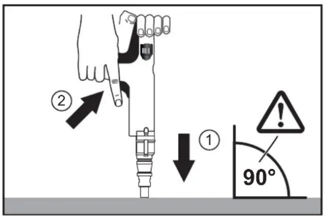
Firmly grab the Powder Actuated Tool with both hands and push the barrel against the material to be fastened (90° angle, device facing downward) (1).
→Pull the trigger (2).
5 Inspection and cleaning
Powder Actuated Tools have to be cleaned after use in order to remove the accumulated carbon due to the combustion gases.

WARNING
Serious injuries due to accidental triggering
→Remove the cartridge strip.
→Remove the shooting nail.
CAUTION
Hot surfaces
→Let the Powder Actuated Tool cool down.
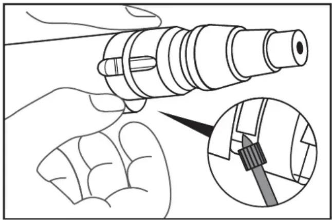
5.1 Disassembling the powder actuated tool
NOTICE Parts may be damaged during disassembly. Do not use damaged (bent) attachment clips any more.
→Lift the attachment clips slightly using a sharp object and remove them.
natural_image
Illustration of a hand holding a mechanical component with an inset showing a close-up of a tool interacting with it (no text or symbols present)→Pull back the piston stop slightly and remove it.
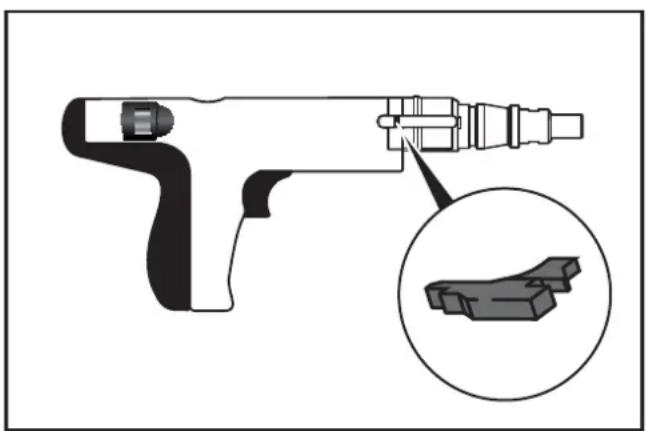
natural_image
Technical illustration of a handheld tool with an inset close-up showing a 3D block structure (no text or symbols)Remove the piston group.
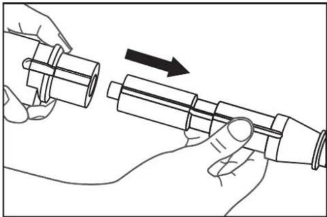
natural_image
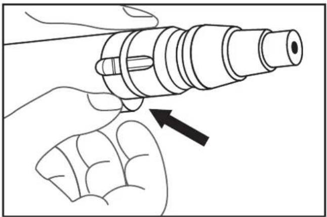
Illustration of hands assembling a mechanical component with an arrow indicating motion (no text or symbols)NOTICE Steel ball may fall out.
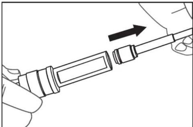
→Lift the attachment clip of the piston guide slightly using a sharp object and remove it.

natural_image
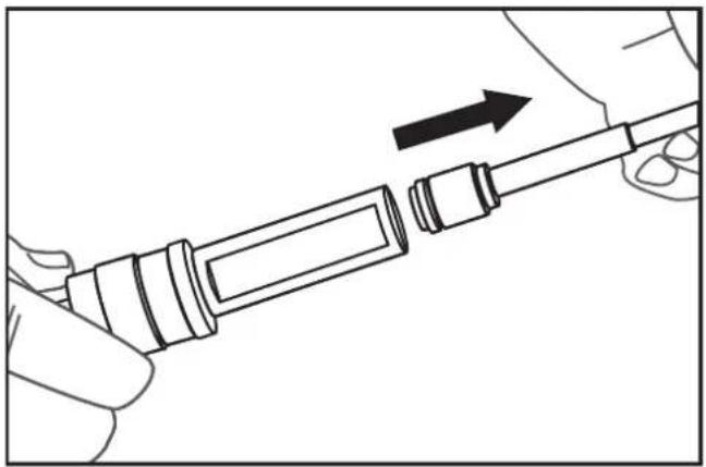
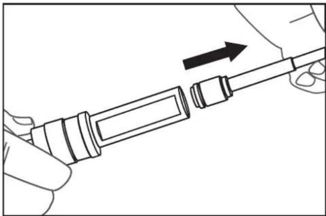
Illustration of hands using a tool to adjust or install a mechanical component, with an inset showing a close-up of the component (no text or symbols present)Remove the piston.
natural_image
Line drawing of a hand holding a mechanical component with an arrow indicating direction (no text or symbols)5.2 Checking and cleaning the interior parts of the device
Clean all parts with oil and wire brushes.
Remove oil residue using a dry cloth.
Check the interior parts of the device. Replace damaged or worn parts.
→Clean piston with oil and a wire brush. Lightly oil the piston shaft.
→Check the piston and piston rings for damage and wear.
→Check the piston shaft.
Replace the piston if the surface of the piston shaft has worn diagonally or has suffered general wear and tear. If the length of the end piece of the piston shaft is less than 5 mm, then the piston has to be changed.

→Clean the piston guide with a round wire brush.
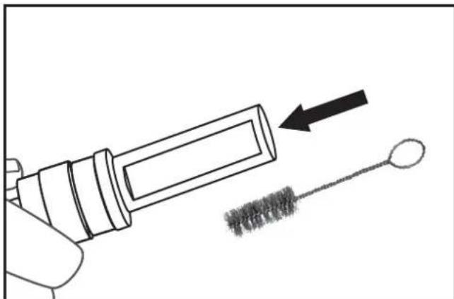
natural_image
Illustration of a hand holding a syringe with an arrow pointing to a brush tip, no text or symbols present5.3 Assembling the powder actuated tool
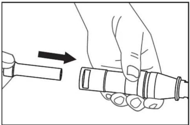
Insert the piston shaft into the piston guide.
natural_image
Line drawing of a hand holding a cylindrical tool with an arrow indicating direction (no text or symbols)Insert the piston guide into the piston group.

natural_image
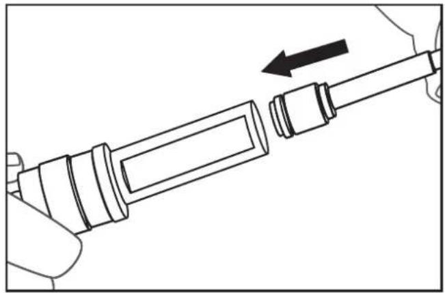
Illustration of a hand holding a cylindrical device with an arrow indicating motion (no text or symbols)→Check the positions of the grooves and insert the piston group right up to the stop.
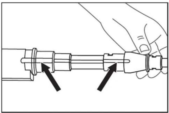
natural_image
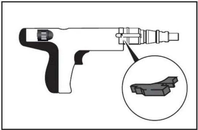
Line drawing of a hand holding a mechanical component with two arrows indicating direction (no text or symbols)→Insert the piston stop into the groove on the right side of the device and slightly push it forward.
natural_image
Diagram of a handheld device with an inset close-up showing a 3D block structure (no text or symbols)→Insert the steel ball.
→Secure the piston group using attachment clips.
natural_image
Illustration of a hand holding a cylindrical mechanical component with an arrow pointing to it (no text or symbols present)5.4 Cleaning the device surfaces
NOTICE Damage to surfaces: Do not use any thinners, solvents, gasoline, etc. for cleaning purposes.
– Clean the Powder Actuated Tool using dry cloths.
– Clean the tool box with dry cloths and compressed air.
6 Technical data
Type PA3500
| Category Indirect fi ring, low speed | |
| Length 340 mm | |
| Weight 2.35 kg | |
| Setting Frequency | max. 500 shooting nails per hour |
| Power Regulation | 3 charge/fi ring strengths,6-stage power regulation using a power regulator |
| Sound Pressure Level+/- 2 dB (A)* | L_pA (Measurement area)99 dB(A) L_pA (Workplace) 104 dB (A) L_pC 138 dB (A) L_WA 112 dB (A) |
| Vibrations < 2.5 m/s2 | |
*Noise measurement according to EN 15895 and using EN ISO 3744, EN ISO 4871 as well as EN ISO 11201.
Measurement conditions: Strongest charge (red) intended to be used with adjusted shooting nail. Triggered on a concrete block, device facing vertically downward. The measured noise emission values and associated measurement uncertainties constitute the upper limit of the values to be expected.
The work environment, workpiece support, workpiece, contact pressing force and so forth affect the noise development at the place of operation and the effects of vibrations on the object.
Shooting nails
| Type Head nails ∅ 7.6 mm | |
| Length, max. | 63 mm (without pre-drilling) |
| 76 mm (with pre-drilling) | |
Cartridge strips
| Calibre*.27 cal. (6.8/11) | |
| Type | Cartridge strips(10 cartridges) |
| Charge/fi ring strengths* | green (3) weak charge |
| yellow (4) medium charge | |
| red (6) very strong charge | |
Only perform troubleshooting measure that are specified here.
The Powder Actuated Tool may only be maintained and repaired by an authorized specialist workshop.
Cartridge strip does not fi re:
| Cause(s) Measure(s) | |
| Barrel not pressed firmly enough against the surface | Press the barrel harder against the surface |
| Malfunction of the cartridge strip | Insert new cartridge strip |
| Powder Actuated Tool defective | Have the Powder Actuated Tool be repaired by an authorized specialist workshop |
Barrel or piston blocked:
| Cause(s) Measure(s) | |
| Powder Actuated Tool has overheated | Let the Powder Actuated Tool cool down |
| Foreign object in the barrel or piston guide | See chapter 5 "Inspection and cleaning" |
| Bent barrel | Have the Powder Actuated Tool be repaired by an authorized specialist workshop |
| Non-approved shooting nails | See chapter 2.3 "Shooting nails" and chapter 6 "Technical data" |
| Powder Actuated Tool defective | Have the Powder Actuated Tool be repaired by an authorized specialist workshop |
Performance weak or fluctuating:
| Cause(s) Measure(s) | |
| Interior parts of the device dirty or worn | See chapter 5"Inspection and cleaning" |
Barrel can only be pressed against the surface with much force:
| Cause(s) Measure(s) | |
| Foreign object in the barrel or piston guide | See chapter 5"Inspection and cleaning" |
| Interior parts of the device dirty or worn | |
| Bent barrel | Have the Powder Actuated Tool be repaired by an authorized specialist workshop |
Barrel is fi rmly pressed against the surface, but the shooting nails are not fi red when pulling the trigger:
| Cause(s) Measure(s) | |
| Barrel not pressed firmly enough against the surface | Press the barrel harder against the surface |
| Non-approved shooting nails | See chapter 2.3 "Shooting nails" and chapter 6 "Technical data" |
| Foreign object in the barrel or piston guide | See chapter 5 "Inspection and cleaning" |
| Powder Actuated Tool defective | Have the Powder Actuated Tool be repaired by an authorized specialist workshop |
Shooting nails do not penetrate deep enough into the material to be fastened:
| Cause(s) Measure(s) | |
| Firing strength too low | Set the fi ring strength (power regulator) to a higher level, see chapter 3.4 „Test attachment“. |
| Insert the cartridge strip with the next higher charge/fi ring strength, see chapter 2.2 „Cartridge strips“ | |
| Shooting nail too long Use a shooting nailTarget material too hard | that matches the target material |
Cause(s) Measure(s)
| Shooting nail strikes hard foreign objects in the target material, such as nails | Aim the Powder Actuated Tool elsewhere |
| Test the Powder Actuated Tool elsewhere on the target material | |
| Powder Actuated Tool has to be serviced | Have the Powder Actuated Tool be serviced/maintained by an authorized specialist workshop |
Shooting nails penetrate too deep into the material to be fastened:
| Cause(s) Measure(s) | |
| Firing strength too high | Set the fi ring strength (power regulator) to a lower level, see chapter 3.4 „Test attachment“. |
| Insert an cartridge strip with a lower charge/ fi ring strength, see chapter 2.2 „Cartridge strips“ | |
| Shooting nail too short | Use a shooting nail that matches the target material |
| Target material too soft | |
| Shooting nail hits cavities or soft foreign objects in the target material | Test the Powder Actuated Tool elsewhere on the target material |
| Test The Powder Actuated Tool on a different target material | |
8 Manufacturer warranty
DEWALT trusts in the quality of its products and therefore offers professional users of the product an outstanding warranty. This warranty is merely an addition and does not affect your rights derived from your contract as a professional user or your legal rights as a private, non-professional user of the device. This warranty is valid within the territories of the Member States of the European Union and the European Free Trade Association.
Full warranty for one year
If your DEWALT product suffers from a fault due to material or production defects within 12 months after purchase, DEWALT guarantees the free replacement of all faulty parts or the free replacement of the device (at our discretion) under the following conditions:
– The product was not handled improperly;
– The product was exposed to normal wear and tear;
– No repair attempts were made by unauthorized persons;
– A proof of purchase is submitted;
- The product is returned complete in its original packaging.
In order to submit a warranty claim, please contact a DEWALT service partner in your area (whose address can be found in the DEWALT catalogue) or contact the DEWALT offi ce specifi ed in this instruction manual. A list of authorized DEWALT customer service workshops and more information regarding our customer service can be found on the Internet an: www.2helpU.com.
9 Declaration of conformity

In accordance with machinery directive
2006/42/EC
Product: Powder Actuated Tool
Type: D EWALT DDF2120400
The designated product corresponds to the provisions of Machinery Directive 2006/42/EC as well as the harmonized EN 15895 standard.
The signatory is responsible for compiling the technical documents and submits this declaration on behalf of D EWALT.
For more information, please contact D EWALT at the following address. For additional addresses, please refer to the backside of this instruction manual.

Colin Earl
Idstein, 22 April 2014
Vice President HTF
Construction and DIY Europe
D-65510, Idstein, Germany
10 C.I.P. approval confirmation
The DEWALT PA3500 device is type-approved and system-tested. The square approval symbol contains the registered approval number "PTB S 824". With this, DEWALT guarantees that the device complies with the approved type.
Inadmissible defects that are detected during operation have to be reported to the authority responsible for the approval (PTB Braunschweig) as well as the Permanent International Commission (Commission Internationale Permanente pour l'Épreuve des Armes à Feu Portatives), Avenue de la Renaissance 30, B-1000 Brussels (Belgium).
Approval of the technical unit consisting of type-approved tool and specified cartridge in a magazine is documented by system approval. The test certificate numbers of the respective system approvals are listed in the following table:
| DEWALTMagazined cartridge stripes for PA3500 | PTBTest certifi cate number of the system approval |
| DEWALT 6,8/11 (.27 cal.), green | PTB Sy 824 DW 13 |
| DEWALT 6,8/11 (.27 cal.), yellow | PTB Sy 824 DW 14 |
| DEWALT 6,8/11 (.27 cal.), red | PTB Sy 824 DW 16 |
HERRAMIENTA DE PÓLVORA PA3500® DDF2120400
1.6 Eliminación
Acero:
natural_image
Diagram of a handheld tool with an arrow indicating direction, no text or symbols present4 Manipulación

ADVERTENCIA
natural_image
Line drawing of a hand holding a mechanical component with an arrow indicating direction (no text or symbols)natural_image
Illustration of a hand using a tool to adjust or install a mechanical component, with an inset showing the close-up of the component (no text or symbols present)natural_image
Illustration of a hand using a tool to cut a mechanical component, with an inset showing a close-up of the component (no text or symbols present)natural_image
Illustration of a hand holding a mechanical component with an inset showing a close-up of a tool inserted into a component (no text or symbols present)natural_image
Diagram of a handheld device with an inset close-up showing a small mechanical component (no text or symbols present)natural_image
Illustration of hands assembling a mechanical component with an arrow indicating motion (no text or symbols)natural_image
Illustration of hands using a tool to adjust or install a component, with an inset showing a magnified view of the tool (no text or symbols present)natural_image
Line drawing of a hand holding a tool with an arrow indicating direction (no text or symbols)natural_image
Illustration of a syringe being inserted into a wire with a magnified view of the brush (no text or symbols)natural_image
Line drawing of a mechanical component with an arrow indicating direction (no text or symbols)natural_image
Illustration of hands holding a cylindrical device with an arrow indicating direction (no text or symbols)natural_image
Illustration of a hand holding a mechanical component with two arrows indicating assembly or adjustment (no text or symbols present)natural_image
Technical illustration of a mechanical device with an inset close-up showing a component detail (no text or symbols)natural_image
Line drawing of a hand holding a cylindrical mechanical component with an arrow pointing to it (no text or symbols present)Construction and DIY Europe
natural_image
Illustration of a hand holding a pen with a 90-degree angle marker (no text or symbols on the diagram itself)Acier :
natural_image
Diagram of a handheld electric tool with an arrow indicating motion direction (no text or symbols)4 Manipulation

AVERTISSEMENT
natural_image
Line drawing of a hand holding a mechanical component with an arrow indicating direction (no text or symbols)natural_image
Illustration of a hand using a tool to insert or install a screwdriver, with an inset showing the process (no text or symbols present)natural_image
Illustration of a hand using a tool to cut a mechanical component, with an inset showing a close-up of a gear mechanism (no text or symbols present)natural_image
Illustration of a hand holding a mechanical component with an inset showing a close-up of a tool inserted into a cylindrical part (no text or symbols present)natural_image
Diagram of a mechanical tool with an inset showing a close-up view of a component (no text or symbols present)natural_image
Illustration of hands assembling a mechanical component with an arrow indicating motion (no text or symbols)natural_image
Illustration of hands using a tool to adjust or install a mechanical component, with an inset showing a close-up of the component (no text or symbols present)Retirez le piston.
natural_image
Line drawing of a hand holding a tool with an arrow indicating direction (no text or symbols)natural_image
Illustration of a hand holding a syringe with an arrow pointing to a textured object (no text or symbols)natural_image
Line drawing of a mechanical component with an arrow indicating direction (no text or symbols)natural_image
Illustration of a hand holding a pen and a cylindrical device with an arrow indicating motion (no text or symbols)natural_image
Line drawing of a hand holding a mechanical component with two arrows indicating direction (no text or symbols)natural_image
Technical illustration of a handheld tool with an inset close-up showing a 3D block structure (no text or symbols)natural_image
Illustration of a hand holding a cylindrical mechanical component with an arrow pointing to it (no text or symbols present)Cause(s) Solution (s)
Colin Earl
natural_image
Illustration of a hand holding a tool with a 90-degree angle marker (no text or symbols on the tool itself)Acciaio:
natural_image
Diagram of a handheld electric gun with an arrow indicating motion direction (no text or symbols)4 Utilizzo

AVVERTENZA
natural_image
Line drawing of a hand holding a mechanical component with an arrow indicating direction (no text or symbols)natural_image
Illustration of a hand using a tool to interact with a screwdriver, showing a magnified inset of the tool (no text or symbols present)natural_image
Illustration of a hand using a tool to cut a mechanical component, with an inset showing a close-up of a gear mechanism (no text or symbols present)natural_image
Illustration of a hand holding a mechanical component with an inset showing a close-up of a tool inserted into a housing (no text or symbols present)natural_image
Technical illustration of a mechanical tool with an inset close-up showing a 3D component detail (no text or symbols)natural_image
Illustration of hands connecting a mechanical component to a shaft, with an arrow indicating direction (no text or symbols present)natural_image
Illustration of hands using a tool to adjust or install a mechanical component, with an inset showing a close-up of the component (no text or symbols present)natural_image
Line drawing of a hand holding a tool with an arrow indicating direction (no text or symbols)natural_image
Illustration of a syringe being inserted into a wire with a magnified view of the brush (no text or symbols)natural_image
Line drawing of a mechanical component with an arrow indicating direction (no text or symbols)natural_image
Illustration of hands holding a pen or tool with an arrow indicating direction (no text or symbols)natural_image
Line drawing of a hand holding a mechanical component with two arrows indicating assembly or adjustment (no text or symbols present)natural_image
Technical illustration of a handheld device with an inset close-up showing a 3D model (no text or symbols present)natural_image
Illustration of a hand holding a cylindrical mechanical component with an arrow pointing to it (no text or symbols present)Construction and DIY Europe
Bescherming van personen:
Staal:
natural_image
Diagram of a handheld electric tool with an arrow indicating motion direction (no text or symbols)4 Gebruik

WAARSCHUWING
natural_image
Line drawing of a hand holding a mechanical component with an arrow indicating direction (no text or symbols)natural_image
Illustration of a hand using a tool to adjust or install a mechanical component, with an inset showing the close-up of the component (no text or symbols present)natural_image
Illustration of a hand using a tool to cut a mechanical component, with an inset showing a close-up of the component (no text or symbols present)4.3 Schietnagels afvuren

WAARSCHUWING
natural_image
Illustration of a hand holding a mechanical component with an inset showing a close-up of a tool (no text or symbols present)natural_image
Diagram of a handheld device with an inset close-up showing a 3D block structure (no text or symbols)natural_image
Illustration of hands connecting a mechanical component to a shaft, with an arrow indicating direction (no text or symbols present)NB De stalen bal kan eruit vallen.
natural_image
Line drawing of hands using a tool to adjust or install a mechanical component, with an inset showing a close-up of the component (no text or symbols present)natural_image
Line drawing of a hand holding a mechanical component with an arrow indicating direction (no text or symbols)natural_image
Illustration of a syringe and a stick with a brush, showing a hand holding the syringe (no text or symbols present)5.3 De kruitschiethamer assembleren
natural_image
Line drawing of a hand holding a cylindrical tool with an arrow indicating direction (no text or symbols)natural_image
Illustration of a hand holding a cylindrical device with an arrow indicating motion (no text or symbols)natural_image
Line drawing of a hand holding a mechanical component with two arrows indicating direction (no text or symbols)natural_image
Technical illustration of a handheld device with an inset close-up showing a 3D model (no text or symbols present)natural_image
Illustration of a hand holding a cylindrical mechanical component with an arrow pointing to it (no text or symbols present)5.4 De behuizing reinigen
Idstein, 22 April 2014
Vice President HTF
Construction and DIY Europe
Stål:
natural_image
Diagram of a handheld electric tool with an arrow indicating motion direction (no text or symbols)4 Händtering

ADVARSEL
natural_image
Line drawing of a hand holding a mechanical component with an arrow indicating direction (no text or symbols)natural_image
Illustration of a hand using a tool to adjust or install a mechanical component, with an inset showing the close-up of the component (no text or symbols present)natural_image
Illustration of a hand using a tool to cut a mechanical component, with an inset showing a close-up of the component (no text or symbols present)natural_image
Illustration of a hand holding a mechanical component with an inset showing a close-up of a tool (no text or symbols present)natural_image
Technical illustration of a handheld device with an inset close-up showing a 3D model (no text or symbols present)Fjern stempelgruppen.

natural_image
Illustration of hands assembling a mechanical component with an arrow indicating motion (no text or symbols)natural_image
Illustration of hands using a tool to adjust or install a component, with an inset showing a close-up of the tool (no text or symbols present)Fjern stempelet.
natural_image
Line drawing of a hand holding a tool with an arrow indicating direction (no text or symbols)natural_image
Illustration of a syringe being inserted into a bulb with a magnified view of the bulb (no text or symbols)natural_image
Line drawing of a mechanical component with an arrow indicating direction (no text or symbols)- Sett stempelstyringen inn i stempelgruppen.
natural_image
Illustration of a hand holding a pen or tool with an arrow indicating direction (no text or symbols present)natural_image
Line drawing of a hand holding a mechanical component with two arrows indicating direction (no text or symbols)natural_image
Diagram of a handheld device with an inset close-up showing a 3D block component (no text or symbols present)→Sett inn stålkulen.
→Fest stempelgruppen med påspenningsklips.

natural_image
Illustration of a hand holding a cylindrical device with an arrow pointing to it, no text or symbols present.Aço:
natural_image
Diagram of a handheld electric tool with an arrow indicating motion direction (no text or symbols)4 Manuseamento

AVISO
natural_image
Line drawing of a hand holding a mechanical component with an arrow indicating direction (no text or symbols)4.2 Inserir e retirar cartuchos
Inserir os cartuchos
natural_image
Illustration of a hand using a tool to adjust or install a mechanical component, with an inset showing the tool being inserted (no text or symbols present)natural_image
Illustration of a hand using a tool to cut a mechanical component, with an inset showing a close-up of the component (no text or symbols present)4.3 Disparar os pregos

AVISO
natural_image
Illustration of a hand holding a mechanical component with an inset showing a close-up of a tool inserted into a cylindrical part (no text or symbols present)natural_image
Diagram of a handheld device with a magnified inset showing a small mechanical component (no text or symbols present)natural_image
Illustration of hands assembling a mechanical component with an arrow indicating motion (no text or symbols)natural_image
Illustration of hands using a tool to adjust or install a mechanical component, with an inset showing a close-up of the component (no text or symbols present)Retire o pistão.
natural_image
Line drawing of a hand holding a tool with an arrow indicating direction (no text or symbols)natural_image
Illustration of a hand holding a syringe with an arrow pointing to a textured brush (no text or symbols)natural_image
Line drawing of a hand holding a mechanical component with an arrow indicating direction (no text or symbols)natural_image
Illustration of a hand holding a cylindrical device with an arrow indicating direction (no text or symbols)natural_image
Line drawing of a hand holding a mechanical component with two arrows indicating direction (no text or symbols)natural_image
Diagram of a handheld tool with an inset close-up showing a 3D block structure (no text or symbols)natural_image
Illustration of a hand holding a cylindrical mechanical component with an arrow pointing to it (no text or symbols present)Construction and DIY Europe
Teräs:
natural_image
Diagram of a handheld device with an arrow indicating motion or force direction (no text or symbols present)4 Käsittely

VAROITUS
natural_image
Line drawing of a hand holding a mechanical component with an arrow indicating direction (no text or symbols)natural_image
Illustration of a hand using a tool to adjust or install a mechanical component, with an inset showing the close-up of the component (no text or symbols present)natural_image
Illustration of a hand using a tool to cut a mechanical component, with an inset showing a close-up of the component (no text or symbols present)4.3 Naulojen laukaisminen

VAROITUS
natural_image
Illustration of a hand holding a mechanical component with an inset showing a close-up of a tool inserted into a cylindrical part (no text or symbols present)natural_image
Technical illustration of a handheld device with an inset close-up showing a mechanical component (no text or symbols)natural_image
Illustration of hands assembling a mechanical component with an arrow indicating motion (no text or symbols)natural_image
Illustration of hands using a tool to adjust or install a mechanical component, with an inset showing a close-up of the component (no text or symbols present)Poista mäntä.

natural_image
Line drawing of a hand holding a screwdriver with an arrow indicating direction (no text or symbols)natural_image
Illustration of a syringe and a swab with an arrow indicating direction (no text or symbols)natural_image
Line drawing of a hand holding a cylindrical tool with an arrow indicating direction (no text or symbols)natural_image
Illustration of hands holding a pen or tool with an arrow indicating direction (no text or symbols)natural_image
Illustration of a hand holding a mechanical component with two arrows pointing to a shaft (no text or symbols present)natural_image
Technical illustration of a handheld device with an inset close-up showing a mechanical component (no text or symbols)natural_image
Line drawing of a hand holding a cylindrical mechanical component with an arrow pointing to it (no text or symbols present)Construction and DIY Europe
D-65510, Idstein, Germany
natural_image
Illustration of a hand holding a pen with a 90-degree angle marker (no text or symbols on the diagram itself)Personskydd:
Stål:
natural_image
Diagram of a handheld electric gun with an arrow indicating motion direction (no text or symbols)4 Handhavande

WARNING
natural_image
Line drawing of a hand holding a mechanical component with an arrow indicating direction (no text or symbols)natural_image
Illustration of a hand using a tool to adjust or install a mechanical component, with an inset showing the tool's internal mechanism (no text or symbols present)natural_image
Illustration of a hand using a tool to cut a mechanical component, with an inset showing a close-up of a mechanical component (no text or symbols present)natural_image
Illustration of a hand holding a mechanical component with an inset showing a close-up of a tool (no text or symbols present)natural_image
Technical illustration of a handheld device with an inset close-up showing a mechanical component (no text or symbols present)Ta bort kolvgruppen.
natural_image
Illustration of hands assembling a mechanical component with an arrow indicating motion (no text or symbols)natural_image
Line drawing of hands using a tool to adjust or install a mechanical component, with an inset showing a close-up of the component (no text or symbols present)→Ta bort kolven.

natural_image
Line drawing of a hand holding a tool with an arrow indicating direction (no text or symbols)natural_image
Diagram showing a syringe being inserted into a bulb with a magnified view of the bulb (no text or symbols)natural_image
Line drawing of a hand holding a cylindrical tool with an arrow indicating direction (no text or symbols)natural_image
Illustration of a hand holding a cylindrical device with an arrow indicating direction (no text or symbols)natural_image
Illustration of a hand holding a mechanical component with two arrows pointing to a shaft (no text or symbols present)natural_image
Diagram of a handheld device with an inset close-up showing a 3D model (no text or symbols present)natural_image
Illustration of a hand holding a cylindrical mechanical component with an arrow pointing to it (no text or symbols present)Colin Earl
Idstein, 22 april 2014
Vice President HTF
Construction and DIY Europe
natural_image
Illustration of a hand holding a tool with a 90-degree angle marker (no text or symbols on the tool itself)Προστασία ατόμων:
Χάλυβας:
natural_image
Diagram of a handheld electric drill with an arrow indicating motion direction (no text or symbols)4 Χειρισμός

ΠΡΟΕΙΔΟΠΟΙΗΣΗ
natural_image
Line drawing of a hand holding a mechanical component with an arrow indicating direction (no text or symbols)natural_image
Illustration of a hand using a tool to adjust or install a mechanical component, with an inset showing the tool's internal mechanism (no text or symbols present)natural_image
Illustration of a hand using a tool to cut a mechanical component, with an inset showing a close-up of the component (no text or symbols present)natural_image
Illustration of a hand holding a mechanical component with an inset showing a close-up of a tool (no text or symbols present)natural_image
Technical illustration of a handheld tool with an inset close-up showing a mechanical component (no text or symbols)natural_image
Illustration of hands connecting a mechanical component to a shaft, with an arrow indicating direction (no text or symbols present)natural_image
Illustration of hands using a tool to adjust or install a mechanical component, with an inset showing a close-up of the component (no text or symbols present)natural_image
Line drawing of a hand holding a tool with an arrow indicating direction (no text or symbols)natural_image
Illustration of a syringe being inserted into a wire with a magnified view of the bulb (no text or symbols)natural_image
Line drawing of a mechanical component with an arrow indicating direction (no text or symbols)natural_image
Illustration of hands holding a pen or tool with an arrow indicating direction (no text or symbols present)natural_image
Illustration of a hand holding a mechanical component with two arrows indicating assembly or adjustment (no text or symbols present)natural_image
Technical illustration of a mechanical tool with an inset close-up showing a 3D component detail (no text or symbols present)natural_image
Line drawing of a hand holding a cylindrical mechanical component with an arrow pointing to it (no text or symbols present)Colin Earl
D-65510, Idstein, Germany