DCF520 - Screwdriver DEWALT - Free user manual and instructions
Find the device manual for free DCF520 DEWALT in PDF.

User questions about DCF520 DEWALT
0 question about this device. Answer the ones you know or ask your own.
Ask a new question about this device
Download the instructions for your Screwdriver in PDF format for free! Find your manual DCF520 - DEWALT and take your electronic device back in hand. On this page are published all the documents necessary for the use of your device. DCF520 by DEWALT.
USER MANUAL DCF520 DEWALT
Fig. A
DCF510 DCF520
DCF512, DCF513, DCF514, DCF512E, DCF513E, DCF514E
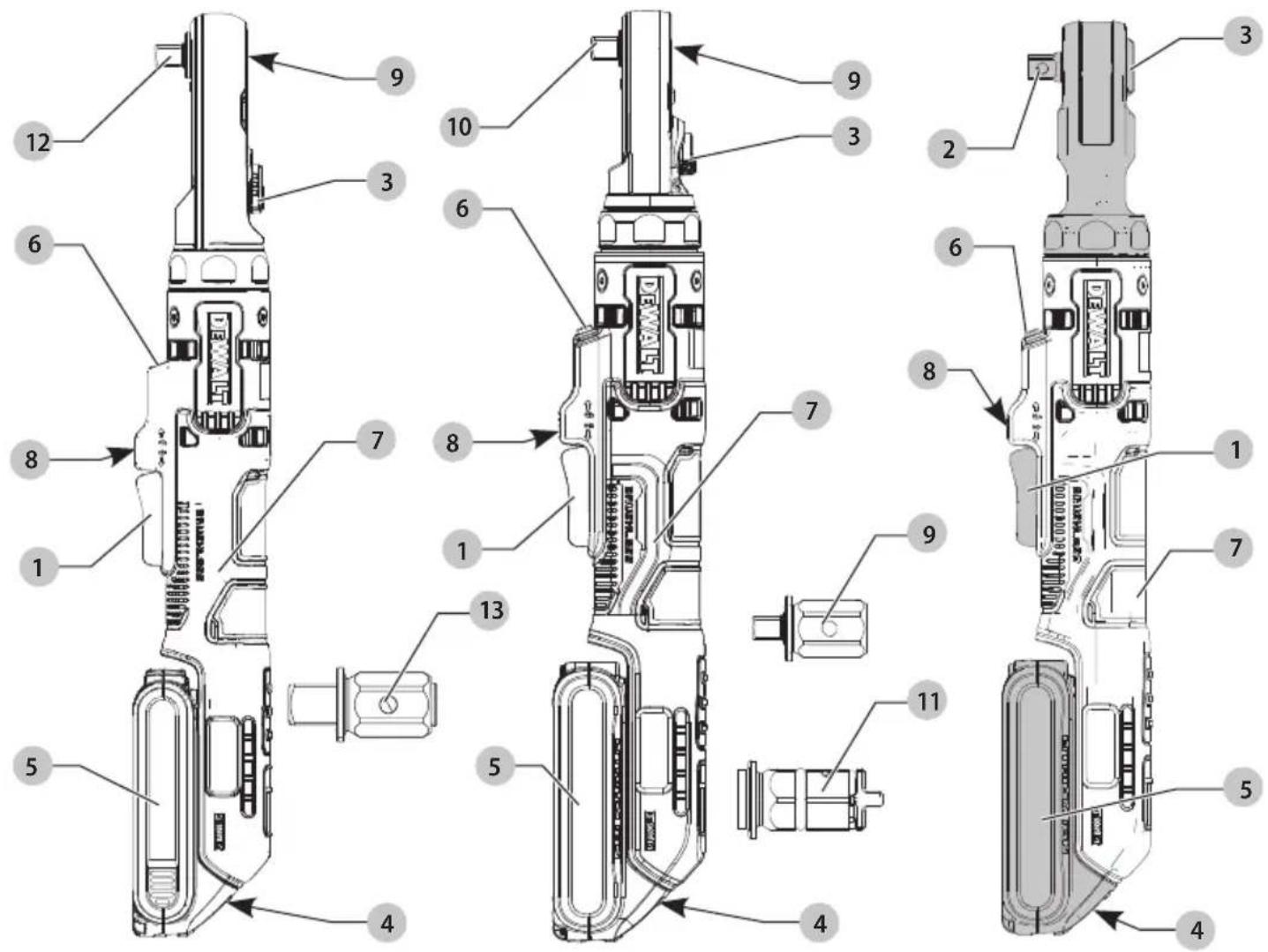
Fig. E
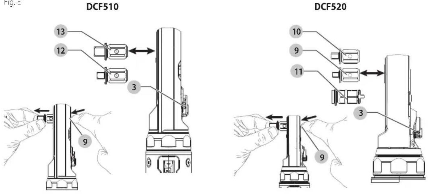
Fig. F
DCF520
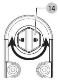
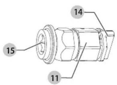
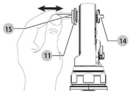
Fig. G Fig. H
DCF510, DCF520
DCF512, DCF513, DCF514, DCF512E, DCF513E, DCF514E
18V SKRALDE DCF510, DCF512, DCF513, DCF514, DCF520 18V FORLÄENGET SKRALDE DCF512E, DCF513E, DCF514E
| Kat. nr. O/MIN Ft.-Lbs. Nm |
| DCF510 0–300 0–75 0–101 |
| DCF512 0–250 0–70 0–95 |
| DCF512E 0–250 0–70 0–95 |
| DCF513 0–250 0–70 0–95 |
| DCF513E 0–250 0–70 0–95 |
| DCF514 0–250 0–45 0–54 |
| DCF514E 0–250 0–45 0–54 |
| DCF520 0–450 0–50 0–67 |

*For direct access, replace "xxx" with the product's model number given on the product rating label or packaging.
- Instruction Manual
• Declaration of Conformity (DoC) - Product Emission Data (PED): Information about Noise, Vibration and Dust (not applicable for all products)

WARNING: Read all safety warnings, instructions, illustrations, and specifications in this manual,

including the battery and charger sections provided in an original tool manual or the separate Batteries and Chargers manual. Manuals can be obtained by contacting
Customer Service (refer to the back page of this manual).
Technical Data
| DCF510 DCF512 DCF513 DCF514 | ||
| Voltage | V_DC 18 18 18 | 18 |
| Type | 1 1 1 | 1 |
| No load speed 0–300 0–250 0–250 0–250 | ||
| Length | mm 381 360 360 | 336 |
| Weight(without battery pack) | kg 1.20 1.10 1.10 1.10 | |
| DCF520 DCF512E DCF513E DCF514E | |||||
| Voltage | V_DC | 18 | 18 | 18 | 18 |
| Type | 1 | 1 | 1 | 1 | |
| No load speed | 0-450 | 0-250 | 0-250 | 0-250 | |
| Length | mm | 362 | 463 | 463 | 460 |
| Weight (without battery pack) | kg | 1.10 1.30 | 1.30 | 1.30 | |
Definitions: Safety Guidelines
The definitions below describe the level of severity for each signal word. Please read the manual and pay attention to these symbols.
RANGER: Indicates an imminently hazardous situation which, if not avoided, will result in death or serious injury.
WARNING: Indicates a potentially hazardous situation which, if not avoided, could result in death or serious injury.
AUTION: Indicates a potentially hazardous situation which, if not avoided, may result in minor or moderate injury. NOTICE: Indicates a practice not related to personal injury which, if not avoided, may result in property damage.
Denotes risk of electric shock.
Denotes risk of fire.
GENERAL POWER TOOL SAFETY WARNINGS
WARNING: Read all safety warnings, instructions, illustrations and specifications provided with this power tool. Failure to follow all instructions listed below may result in electric shock, fire and/or serious injury.

SAVE ALL WARNINGS AND INSTRUCTIONS FOR FUTURE REFERENCE
The term "power tool" in the warnings refers to your mains-operated (corded) power tool or battery-operated (cordless) power tool.
Work Area Safety
a) Keep work area clean and well lit. Cluttered or dark areas invite accidents.
b) Do not operate power tools in explosive atmospheres, such as in the presence of flammable liquids, gases or dust. Power tools create sparks which may ignite the dust or fumes.
c) Keep children and bystanders away while operating a power tool. Distractions can cause you to lose control.
Electrical Safety
d) Power tool plugs must match the outlet. Never modify the plug in any way. Do not use any adapter plugs with earthed (grounded) power tools. Unmodified plugs and matching outlets will reduce risk of electric shock.
e) Avoid body contact with earthed or grounded surfaces, such as pipes, radiators, ranges and refrigerators. There is an increased risk of electric shock if your body is earthed or grounded.
f) Do not expose power tools to rain or wet conditions.
Water entering a power tool will increase the risk of electric shock.
g) Do not abuse the cord. Never use the cord for carrying, pulling or unplugging the power tool. Keep cord away from heat, oil, sharp edges or moving parts. Damaged or entangled cords increase the risk of electric shock.
h) When operating a power tool outdoors, use an extension cord suitable for outdoor use. Use of a cord suitable for outdoor use reduces the risk of electric shock.
i) If operating a power tool in a damp location is unavoidable, use a residual current device (RCD) protected supply. Use of an RCD reduces the risk of electric shock.
Personal Safety
j) Stay alert, watch what you are doing and use common sense when operating a power tool. Do not use a power tool while you are tired or under the influence of drugs, alcohol or medication. A moment of inattention while operating power tools may result in serious personal injury.
k) Use personal protective equipment. Always wear eye protection. Protective equipment such as a dust mask, non-skid safety shoes, hard hat or hearing protection used for appropriate conditions will reduce personal injuries.
1) Prevent unintentional starting. Ensure the switch is in the off-position before connecting to power source and/or battery pack, picking up or carrying the tool. Carrying power tools with your finger on the switch or energising power tools that have the switch on invites accidents.
m) Remove any adjusting key or wrench before turning the power tool on. A wrench or a key left attached to a rotating part of the power tool may result in personal injury.
n) Do not overreach. Keep proper footing and balance at all times. This enables better control of the power tool in unexpected situations.
o) Dress properly. Do not wear loose clothing or jewellery. Keep your hair and clothing away from moving parts. Loose clothes, jewellery or long hair can be caught in moving parts.
p) If devices are provided for the connection of dust extraction and collection facilities, ensure these are connected and properly used. Use of dust collection can reduce dust-related hazards.
q) Do not let familiarity gained from frequent use of tools allow you to become complacent and ignore tool safety principles. A careless action can cause severe injury within a fraction of a second.
Power Tool Use and Care
r) Do not force the power tool. Use the correct power tool for your application. The correct power tool will do the job better and safer at the rate for which it was designed.
s) Do not use the power tool if the switch does not turn it on and off. Any power tool that cannot be controlled with the switch is dangerous and must be repaired.
t) Disconnect the plug from the power source and/or remove the battery pack, if detachable, from the power tool before making any adjustments, changing accessories, or storing power tools. Such preventive safety measures reduce the risk of starting the power tool accidentally.
u) Store idle power tools out of the reach of children and do not allow persons unfamiliar with the power tool or these instructions to operate the power tool. Power tools are dangerous in the hands of untrained users.
v) Maintain power tools and accessories. Check for misalignment or binding of moving parts, breakage of parts and any other condition that may affect the power tool's operation. If damaged, have the power tool repaired before use. Many accidents are caused by poorly maintained power tools.
w) Keep cutting tools sharp and clean. Properly maintained cutting tools with sharp cutting edges are less likely to bind and are easier to control.
x) Use the power tool, accessories and tool bits, etc. in accordance with these instructions, taking into account the working conditions and the work to be performed. Use of the power tool for operations different from those intended could result in a hazardous situation.
y) Keep handles and grasping surfaces dry, clean and free from oil and grease. Slippery handles and grasping surfaces do not allow for safe handling and control of the tool in unexpected situations.
Battery Tool Use and Care
z) Recharge only with the charger specified by the manufacturer. A charger that is suitable for one type of battery pack may create a risk of fire when used with another battery pack.
aa) Use power tools only with specifically designated battery packs. Use of any other battery packs may create a risk of injury and fire.
ab) When battery pack is not in use, keep it away from other metal objects, like paper clips, coins, keys, nails, screws or other small metal objects, that can make a connection from one terminal to another. Shorting the battery terminals together may cause burns or a fire.
ac) Under abusive conditions, liquid may be ejected from the battery; avoid contact. If contact accidentally occurs, flush with water. If liquid contacts eyes, additionally seek medical help. Liquid ejected from the battery may cause irritation or burns.
ad) Do not use a battery pack or tool that is damaged or modified. Damaged or modified batteries may exhibit unpredictable behaviour resulting in fire, explosion or risk of injury.
ae) Do not expose a battery pack or tool to fire or excessive temperature. Exposure to fire or temperature above 130 °C may cause explosion.
af) Follow all charging instructions and do not charge the battery pack or tool outside the temperature range specified in the instructions. Charging improperly or at temperatures outside the specified range may damage the battery and increase the risk of fire.
Service
ag) Have your power tool serviced by a qualified repair person using only identical replacement parts. This will ensure that the safety of the power tool is maintained.
ah) Never service damaged battery packs. Service of battery packs should only be performed by the manufacturer or authorised service providers.
Safety Instructions for Ratchet Tools
- Hold the power tool by insulated gripping surfaces, when performing an operation where the fastener may contact hidden wiring. Fasteners contacting a "live" wire may make exposed metal parts of the tool "live" and could give the operator an electric shock.
- Use clamps or another practical way to secure and support the workpiece to a stable platform. Holding the work by your hand or against the body leaves it unstable and may lead to loss of control.
• Air vents often cover moving parts and should be avoided. Loose clothing, jewellery or long hair can be caught in moving parts. - Do not operate this tool for long periods of time. Vibration caused by tool action may be harmful to your hands and arms. Use gloves to provide extra cushion and limit exposure by taking frequent rest periods.
- Accessories and tools get hot during operation. Wear gloves when touching them.
Residual Risks
In spite of the application of the relevant safety regulations and the implementation of safety devices, certain residual risks cannot be avoided. These are:
- Impairment of hearing.
- Risk of personal injury due to flying particles.
- Risk of burns due to accessories becoming hot during operation.
- Risk of personal injury due to prolonged use.
Battery Type
These battery packs may be used:
| Battery (kg) Battery (kg) | |
| DCB546 1.08 DCB185 0.35 | |
| DCB547/G 1.46 DCB187 0.54 | |
| DCB548 1.46 DCB188 0.95 | |
| DCB549 2.12 DCB189 0.54 | |
| DCB181 0.35 DCBP034/G 0.32 | |
| DCB182 0.61 DCBP518/G 0.75 | |
| DCB183/B/G 0.40 DCB1880 0.98 | |
| DCB184/B/G 0.62 DCBP318 0.50 |
Refer to the battery/charger manual for more information.
The following chargers can be used: DCB1104.
Markings on Tool
The following pictograms are shown on the tool:

Read instruction manual before use.

Wear ear protection.

Visible radiation. Do not stare into light.
Date Code Position (Fig. B)
The production date code 10 consists of a 4-digit year followed by a 2-digit week and is extended by a 2-digit factory code.
Description (Fig. A)
WARNING: Never modify the power tool or any part of it.
Damage or personal injury could result.
1 Trigger switch
2 Square anvil
3 Forward/reverse dial
4 Worklight
5 Main handle
6 Lock-off button
7 Anvil release button
8 1/4" drive interchangeable anvil (DCF520)
9 3/8" drive interchangeable anvil (DCF520)
10 1/4" low profile hex interchangeable anvil (DCF520)
11 3/8" drive interchangeable anvil (DCF510)
12 1/2" drive interchangeable anvil (DCF510)
13 Battery pack
14 Battery release button
^† Included in some packages.
Intended Use
These powered ratchets are designed for light duty fastening applications. These powered ratchets are not torque wrenches. DO NOT use this tool for tightening fasteners to specified torques. An independent calibrated torque measurement device such as a torque wrench should be used when torques are specified.
DO NOT use under wet conditions or in the presence of flammable liquids or gases.
These powered ratchets are professional power tools.
DO NOT let children come into contact with the tool.
Supervision is required when inexperienced operators use this tool.
- Young children and the infirm. This appliance is not intended for use by young children or infirm persons without supervision.
- This product is not intended for use by persons (including children) suffering from diminished physical, sensory or mental abilities; lack of experience, knowledge or skills unless they are supervised by a person responsible for their safety. Children should never be left alone with this product.
ASSEMBLY AND ADJUSTMENTS
WARNING: To reduce the risk of serious personal injury, turn tool off and disconnect battery pack before making any adjustments or removing/installing attachments or accessories. An accidental start-up can cause injury.
WARNING: Use only DEWALT batteries and chargers.
Inserting and Removing the Battery Pack from the Tool (Fig. B)
NOTE: Make sure your battery pack 5 is fully charged.
To Install the Battery Pack into the Tool Handle
- Align the battery pack with the rails inside the tool's handle (Fig. B).
- Slide it into the handle until the battery pack is firmly seated in the tool and ensure that you hear the lock snap into place.
To Remove the Battery Pack from the Tool
- Press the battery release button 4 and firmly pull the battery pack out of the tool handle.
- Insert battery pack into the charger.
Fuel Gauge Battery Packs (Fig. B)
Some DEWALT battery packs include a fuel gauge which consists of three green LED lights that indicate the level of charge remaining in the battery pack.
To actuate the fuel gauge, press and hold the fuel gauge button 11. A combination of the three green LED lights will illuminate, designating the level of charge left. When the level of charge in the battery is below the usable limit, the fuel gauge will not illuminate and the battery will need to be recharged.
NOTE: The fuel gauge is only an indication of the charge left on the battery pack. It does not indicate tool functionality and is subject to variation based on product components, temperature and end-user application.
Proper Hand Position (Fig. C)
WARNING: To reduce the risk of serious personal injury, ALWAYS use proper hand position as shown.
WARNING: To reduce the risk of serious personal injury, ALWAYS hold securely in anticipation of a sudden reaction.
WARNING: Ratchet may stall (if overloaded or improperly used), causing a twist. Always expect the stall. Grip the ratchet firmly to control the twisting action and prevent loss of control which could cause personal injury.
Proper hand position requires one hand on the main handle 7 as shown to control the twisting action of the ratchet.
Anvil (Fig. D)
AUTION: Inspect anvil prior to use. Missing or damaged items should be replaced before use.
To install an accessory on the anvil, align the accessory with the anvil 2. Press the accessory onto the anvil 2.
To remove an accessory, pull the accessory off the anvil 2.
Removing and Installing Anvil (Fig. E)
Choose the appropriate sized interchangeable anvil:
- 3/8" drive interchangeable anvil 12 (DCF510)
- 1/2" drive interchangeable anvil 13 (DCF510)
- 1/4" drive interchangeable anvil 9 (DCF520)
- 3/8" drive interchangeable anvil 10 (DCF520)
NOTE: DCF510 and DCF520 anvils are not interchangeable and are only intended to be used with their specific tool.
To Remove
- With one hand push in the release button 9 and with the other hand pull out on the interchangeable anvil 9, 10, 12, 13 to remove it from the tool.
To Install
- To install an interchangeable anvil, push the desired interchangeable anvil into the tool until you hear an audible click. Tug on the interchangeable anvil 9, 10, 12, 13 to ensure it is secured in place.
Removing and Installing 1/4" Low Profile Hex Interchangeable Anvil (Fig. F)
(DCF520 Only)
WARNING: Use only impact accessories. Non-impact accessories may break and cause a hazardous condition. Inspect accessory prior to use to ensure that it contains no cracks.
NOTE: The holder 15 will only accept 1/4" (6.35 mm) hex accessories.
To Install
- To install the 1/4" low profile hex interchangeable anvil 11, push the anvil into the tool until you hear an audible click.
- Twist the lock dial 14 on the back of the hex anvil clockwise to lock the 1/4" low profile hex interchangeable anvil 11 in place.
To Install an Accessory
- Fully insert the accessory into the 1/4" low profile hex interchangeable anvil 11. The accessory is held in place with the built in magnet.
To Remove an Accessory
- Pull the accessory out of the 1/4" low profile hex interchangeable anvil 11.
To Remove
- Twist the lock dial 14 on the back of the hex anvil counterclockwise to unlock the 1/4" low profile hex interchangeable anvil 11.
- With a thumb or finger, push on the lock dial 14 until the 1/4" low profile hex interchangeable anvil 11 releases from the tool.
OPERATION
Instructions for Use
WARNING: Always observe the safety instructions and applicable regulations.
WARNING: To reduce the risk of serious personal injury, turn tool off and disconnect battery pack before making any adjustments or removing/installing attachments or accessories.
An accidental start-up can cause injury.
Variable Speed Trigger (Fig. A)
The tool is turned on and off by pulling and releasing the variable speed trigger 1. The farther the trigger is depressed, the higher the speed of the tool. The anvil will stop as soon as the trigger switch is fully released.
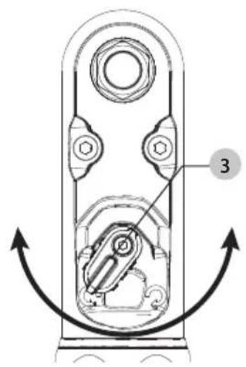
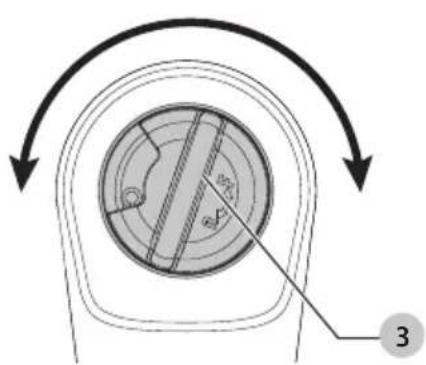
Forward/Reverse Dial (Fig. G, H)
A forward/reverse control dial 3 determines the rotational direction of the tool.
-
To select forward rotation (clockwise), release the trigger and rotate the forward/reverse dial 3 on the head of the tool in a counterclockwise direction.
-
To select reverse rotation (anticlockwise), release the trigger and rotate the forward/reverse dial 3 on the head of the tool in a clockwise direction.
NOTE: The first time the tool is run after changing the direction of rotation, you may hear a click on start up. This is normal and does not indicate a problem.
Lock-off Button (Fig. A)
To lock the tool, slide the lock-off button 8 to the locked position. When the lock-off button is in the locked position, the tool is locked and the trigger switch 1 cannot be pulled.
Worklight (Fig. A)
There is a worklight 6 located on the foot of the tool. The worklight is activated when the trigger switch is depressed. When the trigger is released, the worklight will stay illuminated for up to 20 seconds.
NOTE: The worklight is for lighting the immediate work surface and is not intended to be used as a flashlight.
Usage (Fig. A, D)
WARNING: To reduce the risk of serious personal injury, turn unit off and remove the battery pack before making any adjustments or removing/installing attachments or accessories. An accidental start-up can cause injury.
WARNING: The ratchet may stall if overloaded causing a sudden twist. Always expect the tool to twist. Grip the ratchet firmly to control the twisting action and avoid possible personal injury.
AUTION: Ensure fastener and/or system will withstand the level of torque generated by the tool. Excessive torque may cause breakage and possible personal injury.
| Maximum Tool Applied Torque |
| Cat # RPM Ft.-Lbs. Nm |
| DCF510 0–300 0–75 0–101 |
| DCF512 0–250 0–70 0–95 |
| DCF512E 0–250 0–70 0–95 |
| DCF513 0–250 0–70 0–95 |
| DCF513E 0–250 0–70 0–95 |
| DCF514 0–250 0–45 0–54 |
| DCF514E 0–250 0–45 0–54 |
| DCF520 0–450 0–50 0–67 |
| Maximum Manually Applied Torque |
| Cat # Ft.-Lbs. Nm |
| DCF510 175 237 |
| DCF512 175 237 |
| DCF512E 175 237 |
| DCF513 175 237 |
| DCF513E 175 237 |
| DCF514 60 81 |
| DCF514E 60 81 |
| DCF520 50 67 |
-
Install appropriate accessory onto the anvil 2.
-
Place the accessory on the fastener head. Keep the tool pointed straight at the fastener.
-
Consider the intended operation and select either forward or reverse rotation.
- Press variable speed trigger switch 1 to start operation.
- Release variable speed trigger switch 1 to stop operation.
- If the ratchet stalls, the tool is overloaded or is being improperly used. Release the variable speed trigger switch 1 immediately. Do not press the variable speed trigger switch 1 on and off in an attempt to start a stalled ratchet. Doing so can damage the tool.
- The ratchet can also be used manually for starting stubborn fasteners or snugging by releasing the trigger and applying the torque by hand.
NOTE: Excessive manually applied torque may damage the tool housing or mechanism.
MAINTENANCE
Your power tool has been designed to operate over a long period of time with a minimum of maintenance. Continuous satisfactory operation depends upon proper tool care and regular cleaning.
WARNING: To reduce the risk of serious personal injury, turn tool off and disconnect battery pack before making any adjustments or removing/installing attachments or
accessories. An accidental start-up can cause injury.
The charger and battery pack are not serviceable.
Please refer to the back page of this manual for service centre contact information, or visit www.2helpU.com.
Lubrication
Your power tool requires no additional lubrication.
Cleaning
WARNING: Electrical shock and mechanical hazard. Disconnect the plug from the power source and/or remove the battery pack, if detachable, from the product before cleaning.
WARNING: To ensure safe and efficient operation, always keep the product and the ventilation slots (if applicable) clean. Ventilation slots can be cleaned using a dry, soft non-metallic brush and/or a suitable vacuum cleaner. Do not use water or any cleaning solutions.
WARNING: Blow dirt and dust out of the main housing with dry air as often as dirt is seen collecting in and around the ventilation slots. Wear approved eye protection and approved dust mask when performing this procedure.
WARNING: Never use solvents or other harsh chemicals for cleaning the non-metallic parts of the product. These chemicals may weaken the materials used in these parts. Use a cloth dampened only with water and mild soap. Never let any liquid get inside the product. Never immerse any part of the product into a liquid.
Optional Accessories
WARNING: Since accessories, other than those offered by DEWALT have not been tested with this product, use of such accessories with this tool could be hazardous. To reduce the risk of injury, only DeWAL recommended accessories should be used with this product.
Consult your dealer for further information on the appropriate accessories.
Protecting the Environment

Products/batteries are recyclable, but if marked with the crossed-out bin, they must not be disposed of with normal household waste.
Run the batteries down completely and separate them, and separate any light sources from the product if possible. It is the user's responsibility to delete personal data from the product. Then take the waste to an official waste collection centre or a participating retailer who will often accept it free of charge. Packaging should be discarded based on the marked material code. Operating and safety instructions should only be discarded once the applicable product is no longer in use.
Please check with your local community/municipality for waste management guidance. For further information, visit www.2helpU.com and scan the above QR code.
CARRACA DE 18 V DCF510, DCF512, DCF513, DCF514, DCF520 CARRACA EXTENDIDA DE 18 V DCF512E, DCF513E, DCF514E
| Cat # Tr/min Ft.-Lbs. Nm |
| DCF510 0–300 0–75 0–101 |
| DCF512 0–250 0–70 0–95 |
| DCF512E 0–250 0–70 0–95 |
| DCF513 0–250 0–70 0–95 |
| DCF513E 0–250 0–70 0–95 |
| DCF514 0–250 0–45 0–54 |
| DCF514E 0–250 0–45 0–54 |
| DCF520 0–450 0–50 0–67 |
| Couple maximal appliqué à la main |
| Cat # Ft.-Lbs. Nm |
| DCF510 175 237 |
| DCF512 175 237 |
| DCF512E 175 237 |
| DCF513 175 237 |
| DCF513E 175 237 |
| DCF514 60 81 |
| DCF514E 60 81 |
| DCF520 50 67 |
www.2helpU.com/DoC/ of www.2helpU.com/DoC/index/xxx*
BEWAAR ALLE WAARSCHUWINGEN EN INSTRUCTIES ALS TOEKOMSTIG REFERENTIEMATERIAAL
| Cat # TPM Ft.-Lbs. Nm |
| DCF510 0–300 0–75 0–101 |
| DCF512 0–250 0–70 0–95 |
| DCF512E 0–250 0–70 0–95 |
| DCF513 0–250 0–70 0–95 |
| DCF513E 0–250 0–70 0–95 |
| DCF514 0–250 0–45 0–54 |
| DCF514E 0–250 0–45 0–54 |
| DCF520 0–450 0–50 0–67 |
GENERELLE SIKKERHETSADVARSLER FOR ELEKTRISKE VERKT∅Y
18V CIRCIR DCF510, DCF512, DCF513, DCF514, DCF520
18V UZATMALI CIRCIR DCF512E, DCF513E, DCF514E
www.2helpU.com/DoC/ veya www.2helpU.com/DoC/index/xxx*
| Kat # DEV/DAK Ft.-Lbs. Nm |
| DCF510 0–300 0–75 0–101 |
| DCF512 0–250 0–70 0–95 |
| DCF512E 0–250 0–70 0–95 |
| DCF513 0–250 0–70 0–95 |
| DCF513E 0–250 0–70 0–95 |
| DCF514 0–250 0–45 0–54 |
| DCF514E 0–250 0–45 0–54 |
| DCF520 0–450 0–50 0–67 |
Maksimum Manuel Uygulanan Tork
| Kat # Ft.-Lbs. Nm |
| DCF510 175 237 |
| DCF512 175 237 |
| DCF512E 175 237 |
| DCF513 175 237 |
| DCF513E 175 237 |
| DCF514 60 81 |
| DCF514E 60 81 |
| DCF520 50 67 |