ALK-T7 - Fiber fusion tool Vevor - Free user manual and instructions
Find the device manual for free ALK-T7 Vevor in PDF.

| Product Type | Fusion Fiber Optic Splicer |
| Brand / Model | Vevor ALK-T7 |
| Dimensions (L x W x H) | 166 x 144 x 158 mm |
| Weight | 1.43 kg (without battery) / 1.85 kg (with battery) |
| Power Supply | Li-ion battery 7,800 mAh (autonomy 260 splice+heat cycles, charge 3 h) or AC adapter 13.5 V / 5 A |
| Supported Fiber Types | SM (G.652/G.657), MM (G.651), DS (G.653), NZDS (G.655), BI-1, UBI-1, EDF-1, G657B3- |
| Fiber Diameter | Coating: 80-150 µm; Cladding: 125 to 1,000 µm |
| Alignment | Core alignment, cladding alignment, fine alignment |
| Splice Time | 9 s (standard mode) / 7 s (quick mode) |
| Average Splice Loss | 0.02 dB (SM), 0.01 dB (MM), 0.02 dB (DS), 0.04 dB (NZ-DS) |
| Return Loss | ≥ 60 dB |
| Tensile Test | ≥ 2 N |
| Display | 5-inch color HD LCD, magnification X/Y 210x, X or Y 320x (zoom 1,100x) |
| Result Storage | 100,000 splice records + 10,000 images |
| Heating | Programmable: temperature 10-260 °C, time adjustable per sleeve (2 mm: 10-15 s, 4 mm: 14-19 s, 6 mm: 17-23 s) |
| Data Interface | USB 2.0 for data export |
| Operating Conditions | Temperature: -10 °C to +45 °C; humidity ≤ 95% RH; altitude 0-5,000 m; max wind speed 15 m/s |
| Maintenance | Regular cleaning of V-groove, pressers, radiator; ARC correction; electrode replacement every 5,000 arcs |
| Safety | Overcharge/discharge protection; auto shutdown; sleep mode; do not use in explosive environment |
| Supplied Accessories | AC adapter, battery, car charger (12 V), fiber cutter, stripping pliers, carrying case |
| Warranty | Electronic warranty certificate via www.vevor.com/support |
Frequently Asked Questions - ALK-T7 Vevor
User questions about ALK-T7 Vevor
0 question about this device. Answer the ones you know or ask your own.
Ask a new question about this device
Download the instructions for your Fiber fusion tool in PDF format for free! Find your manual ALK-T7 - Vevor and take your electronic device back in hand. On this page are published all the documents necessary for the use of your device. ALK-T7 by Vevor.
USER MANUAL ALK-T7 Vevor
Technical Support and E-Warranty Certificate www.vevor.com/support
OPTICAL FIBER FUSION SPLICER MODEL:ALK-T7
We continue to be committed to provide you tools with competitive price. "Save Half", "Half Price" or any other similar expressions used by us only represents an estimate of savings you might benefit from buying certain tools with us compared to the major top brands and does not necessarily mean to cover all categories of tools offered by us. You are kindly reminded to verify carefully when you are placing an order with us if you are actually Saving Half in comparison with the top major brands.
MODEL: ALK-T7
natural_image
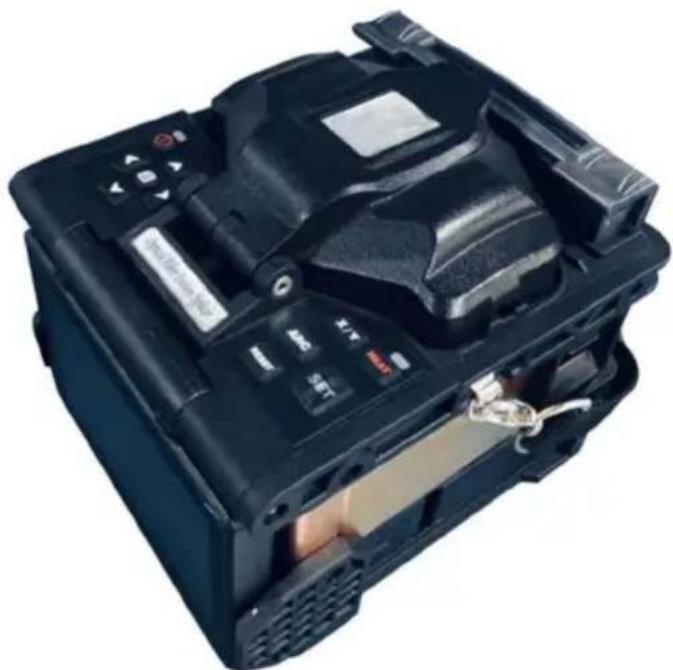
Black electronic device with visible ports and a battery cover, no text or symbols presentNEED HELP? CONTACT US!
Have product questions? Need technical support? Please feel free to contact us:
Technical Support and E-Warranty Certificate www.vevor.com/support
This is the original instruction, please read all manual instructions carefully before operating. VEVOR reserves a clear interpretation of our user manual. The appearance of the product shall be subject to the product you received. Please forgive us that we won't inform you again if
there are any technology or software updates on our product.
IMPORTANT SAFEGUARDS

Warning: This product is designed for splicing glass optical fibers used for communication and it is strictly forbidden to splice other substances. Miss-operation can cause electric shock, fire or personal injury. Please carefully read and observe the following rules for your own safety.
(1) Use the power supply unit provided by this product mix. Do not use other power adapter, battery or power line. Do not use this product under other voltages so as not to cause fire or electric shock.
(2) Don't let liquid such as water or metal material drop into the equipment, otherwise it may cause fire, electric shock or equipment breakdown. Stop using the equipment, unplug the battery socket and contact our maintenance staff once any of the above situation happens.
(3) Must not use the fusion splicer under combustible or explosive environment, otherwise it may cause fire or explosion.
(4) Do not touch the electrodes when the fusion splicer is operating which may cause injury by high voltage generated by arc of electrodes. Ensure that the power is off and the power line has been pulled out when replacing the electrodes.
(5) Once smoking, bad smell or abnormal noise occurs, stop using the fusion splicer immediately, unplug the power plug and contact our maintenance staff. Continue using may cause fire, electric shock or equipment breakdown.
(6) Disassembling or reassembling the fusion splicer, reassembling the battery or power adapter is prohibited to avoid over-heating, burst or fire.
(7) Please strictly follow the operation manual on how to use the battery. Wrong operations can cause battery over-heating, burst or explosion leading to fire or personal injury.
*Please don’t use other methods beyond this manual to charge battery;
*Please don’t throw the battery into fire;
*Please don't connect positive and negative electrodes with reverse
interfaces;
*Please don't charge or discharge under high temperature, fire or directly sunlight;
*Please don't throw or strike battery;
*If the battery electrolyte leaks out, handle it carefully. If the spill contacts skin or eyes inadvertently, you must thoroughly clean and immediately take medical treatment, at the same time inform repair department to process the battery.
(8) Optical fiber fusion splicer must be repaired and debugged by professional. Incorrect repair may cause fire or electrical shock. If a failure occurs, please contact our repair department.
CORRECT DISPOSAL

This product is subject to the provision of European Directive 2012/19/EC. The symbol showing a wheelie bin crossed through indicates that the product requires separate refuse collection in the European Union. This applies to the product and all
accessories marked with this symbol. Products marked as such may not be discarded with normal domestic waste, but must be taken to a collection point for recycling electrical and electronic devices
BATTERY DISPOSAL

To minimize hazards to health and the environment at the end of this product's life, laws dealing with Waste Electrical and Electronic Equipment (WEEE) and The Waste Battery Directive require you to dispose of this product at a suitable collection facility where it will be sent in order to remove the batteries and for appropriate recycling. Please contact your local authorities for more details on recycling and safe disposal of these in your area.
FCC INFORMATION
CAUTION: Changes or modifications not expressly approved by the party responsible for compliance could void the user's authority to operate the equipment!
This device complies with Part 15 of the FCC Rules. Operation is subject to
the following two conditions:
1) This product may cause harmful interference.
2) This product must accept any interference received, including interference that may cause undesired operation.
WARNING: Changes or modifications to this product not expressly approved by the party. Responsible for compliance could void the user's authority to operate the product.
Note: This product has been tested and found to comply with the limits for a Class B digital device pursuant to Part 15 of the FCC Rules, These limits are designed to provide reasonable protection against harmful interference in a residential installation.
This product generates, uses and can radiate radio frequency energy, and if not installed and used in accordance with the instructions, may cause harmful interference to radio communications. However, there is no guarantee that interference will not occur in a particular installation. If this product does cause harmful interference to radio or television reception, which can be determined by turning the product off and on, the user is encouraged to try to correct the interference by one or more of the following measures.
- Reorient or relocate the receiving antenna.
- Increase the distance between the product and receiver.
- Connect the product to an outlet on a circuit different from that to which the receiver is connected.
- Consult the dealer or an experienced radio/TV technician for assistance.
1. Working Environment
1.1 Cautions for use/storage of the splicer:
● Working Temperature: -10^ +45^
● Temperature Limitation: -20^ +55^
● Working Humidity: ≤95%RH (No condensation)
● Maximum Wind Speed: 15m / s
- Storage Conditions: - 10°C \~ + 45°C (With Battery, No Condensation) -20°C + 60°C (No Battery, No Condensation)
Don't use the splicer in environment vulnerable to fire, explosion in case any fire disaster or explosion caused.
Don't use or store the splicer in environment of high temperature or high humidity in case any damages to the machine caused. When the splicer is moved from low temperature environment to environment of higher temperature please take possible warming up measures to eliminate condensation.
Please take suitable dust-resistance measures when using the machine in dusty environment to prevent lots of dust getting into the machines and causing device malfunction.
2. Power Supply
Please use the matching accessories of the splicer and don't use any power adapter, battery or power cord that are not specified in the instruction.
Please don't use the splicer under the voltages that are not specified for the model in case any fire disasters or electric shock caused. The customized car charger power cord is only available for 12V power supply of gasoline cars. In any circumstances, users shall not use it on diesel car with 24V power supply.
3. Battery
Please strictly follow the instructions when using the battery. Improper use of battery may cause battery heating up, burst, explosion, fire disaster or injuries to users.
Please do not charge the battery with methods that are not specified in the manual.
Do not dispose the battery in fire.
Do not reverse the positive and negative poles.
Do not expose the discharging battery under sunshine or in environment with high temperature or in fire.
Do not throw or strike on the battery.
If the battery electrolyte leaks out, please handle it carefully. If user's skin or eyes are contaminated by electrolyte accidentally, please wash it thoroughly and look for medical help immediately. At the same time please inform the after-sales department to handle the battery.
4. Other Cautions
Please prevent any liquid or metal materials getting into the internal structure of the product, or possible fire, electric shock or product malfunction may be caused. Once water or any metal materials get into the product please stop using, cut the power supply, turn off the equipment and contact the maintenance service department.
Please do not touch the electrodes when the equipment is working in case getting hurt by the high voltage. Please do cut the power supply and turn off the equipment before changing electrodes.
Do not disassemble or demolish the splicer, its battery or its adapter in case overheating, burst or fire disaster caused.
Except the components that are allowed to be changed in this manual please do not try to demolish any parts of the splicer. The maintenance or repair of the equipment must be operated by professional technicians from our company, improper operations may cause fire or electric shock.
Do not touch the shrinkable tube in heating process or when it's just finished, as the shrinkable tube is very hot and may cause scald.
Do not touch the splicer, power cord or power plug with wet hands in case electric shock caused.
Do not clean the microscope lens, V groove, screen etc with any chemical materials except alcohol. Otherwise it may cause image blur or spots on screen, or may even cause corrosion or damage of the equipment.
Please prevent the equipment from strong shaking or crash, or the equipment may be damaged. Please transport or store the splicer by dedicated carrying box.
Please do entire machine maintenance once a year to maintain the performance of the splicer.
Production Introduction
This chapter introduces the fundamental parameters of the equipment in details. Reading through this section can help you understand this product and familiarize the product features and tech-environment.
Optical Fiber Fusion Splicer is mainly used for optical fiber cable maintenance and relative operations. Thus it is also called fiber cable splicer. It is a device that uses high precision propulsion structure to push two fibers to get closer to each other and uses an electric arc to melt two optical fibers together at their end faces, to form a single long fiber.
Optical fiber fusion splicers are mainly applied by : Telecom carriers, ISP, network project contractors, laboratories. And they're applied in : Fiber cable network maintenance, telecom projects, emergent repairing, optical experiments, manufacture and testing of optical devices, academic researches in colleges.
Features
(1) Based on the principle of PAS (Lateral Projection System), adopt advanced image detection algorithm;
(2) Double core alignment structure, higher success rate of fusion and lower loss;
(3) Reliability design to enhance the ability of shockproof and dust proof;
(4) Low-power design, many functions can be used at the same time, and can still work for a long time;
(5) Small size and light weight can greatly improve work efficiency;
(6) Adaptive environmental information such as air pressure, temperature and humidity, and automatic discharge compensation.
Technology Indexes
| Main Technical Indexes | |
| Applicable Optical Fiber Types | SM (G.652/G.657), MM (G.651), DS (G.653), NZDS (G.655), BI-1, UBI-1, EDF-1, G657B3-1 |
| Applicable Optical Fiber Core Number | Single core |
| Motor Number 6 Motors, Auto focus | |
| Alignment | Core alignment, Cladding alignment, Fine alignment |
| Applicable Fiber diameter | Cladding Diameter: 80-150μm,Coating diameter: 125~1000μm |
| Splice Mode Pre-store:18 groups, User | define: 982groups |
| Splice Way ARC Splice | |
| Splice Function | Splice by step (semi-automatic and manual)、 automatic splice |
| Boot Time 6s | |
| Average Fusion Splice Loss | 0.02dB(SM), 0.01dB(MM), 0.02dB (CS), 0.04dB(DS), 0.04dB(NZ-DS) |
| Return Loss Better than 60dB | |
| Splice Time | 9SEC(Standard Mode) 7SEC (Fast Mode) |
| Splice Loss Estimation Yes | |
| Tension Test ≥2N | |
| Screen 5 inches TFT true color HD LCD | |
| Language | English, Spanish, German, French, Portuguese, Italian. |
| human-computer interaction mode Button operation | |
| Optical Fiber Magnification Times | X/Y:210 times, X or Y:320 times(Double-click to enlarge 1100 times) |
| Power Supply 10.9V Lithium battery, 13.5V/5A power adapter | |
| Battery | Typically work 260 cycles (Splicing / Heating),Full charge 3 Hours, Recharge Cycle: 500 times,7800mAh Li-battery |
| Power Saving Function Automatic standby, automatic shutdown | |
| Splice Result Save 100000 sets of splice record storage | |
| Image Storage 10000 Image storage | |
| Electrode Rod life ≤5000 | |
| Data Interface USB2.0 can support splicing data export | |
| Operating Environment | Elevation:0~5000m, Relative humidity:0~95%,Temperature:-20°C~55°C,Maximum wind speed:15m/s |
| Storage Environment | Relative humidity:0~95%, Temperature:-30°C~60°C |
| Corrosion resistance | Equipment components, parts and materials used anti-corrosion requirements, and cannot be corroded by fluid contamination |
| Host Appearance | The surface of the host is coated to meet the anti-corrosion requirements. The surface of all painted (plastic) parts; smooth and flat, with consistent color and luster, without scratches, defects, sags, shedding and damage. The surface of the electro plated parts has a metallic luster without cracks, spots, burrs and defects. |
| Splicer Weight 1.43(Without Battery) | 1.85 kg(With Battery) |
| Splicer Size 166D×144W×158H(mm) | |
| Optical fiber Interface judgment standard | Moderate: general quality requirements |
| Applicable Sleeve diameter | 2mm, 3mm, 4mm, 6mm |
| Applicable Sleeve Length | 60mm, 45mm, 40mm, 25mm (FP-03) |
| Heating Time | 2mm tube(10-15S adjustable), 4mm tube (14-19S adjustable), 6mm tube(17-23S adjustable) |
| Heating Temperature | 10-260°C (custom) |
| Auto-Heat | Automatic identification of heating when cover close |
| Night Work Lighting LED Double lights | |
| Aerial Work Optional aerial work platform | |
| Arc Correction Yes | |
| Movable Battery Yes | |
| Energy Consumption Parameter Working power consumption 123W | |
| Battery Safety Protection Overcharge, over discharge protection | |
Introduce of Fusion Splicer
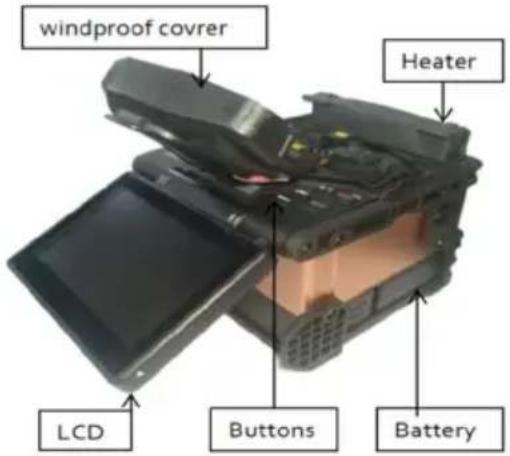
1. Host of Fusion Splicer
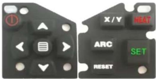
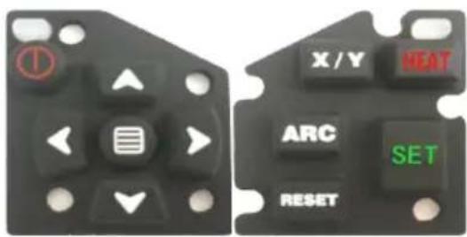
2. Keyboard
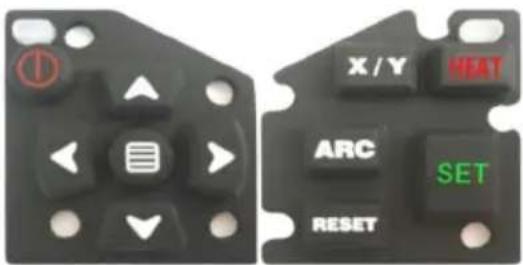
 | Power key | Turn on/off |  | Exit Key /switch key of XY field of view | Return to previous menu, field X, Y switch in Optical fiber mode |
 | Menu/Confirm | Enter menu,Press an enter key on the menu |  | Sleeve heating Key | Start sleeve heating |
 | Up key | Menu cursor moves upward |  | ARC correction | Fast ARC correction |
 | Down key | Menu cursor moves downward |  | Reset key Equipment reset | |
 | Left key | Menu cursor moves to the left, reset the current option |  | Start Key | Start alignment, Start fusion splicing |
 | Right key | Menu cursor moves to the right, reset the current option |
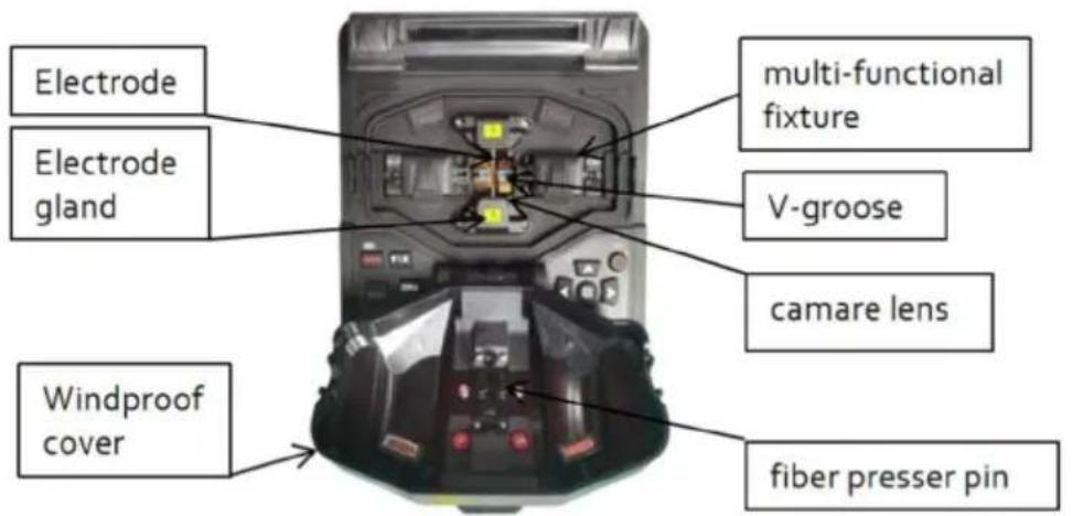
3. Splicer
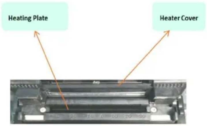
4. Heater
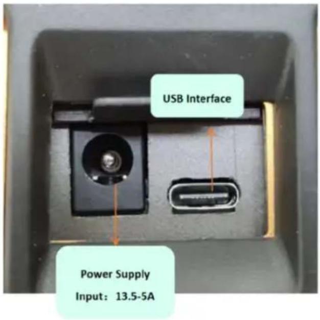
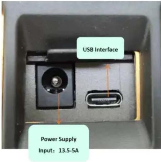
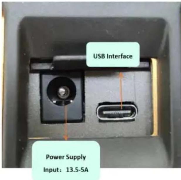
5. Outside Interface
Basic Operation
This chapter describes the fusion splicer's basic operation methods. Read this chapter in detail. It can help you use the splicer correctly, avoid damage and causing abnormal problems.
1. Power Supply
This product can be charged by the following two power supply modes:
(1) Internal lithium battery (with no external power adapter inserted).
(2) External power adapter (with external power adapter inserted).
Attention: Please use the supporting power adapter of this product. Using other adapters can cause anomaly of the equipment.
The power display and charging logo in the upper right corner of the display.

When the battery power is too low, the fusion splicer will display an alarm message on the display screen, and the user should charge the battery pack in time or use a power adapter to supply power.

2. Turn on /off
Short press the power button to turn it on, the power button indicator light turns red, the buzzer emits two beeps, and then the optical fiber observation interface is displayed. Press and hold the power button to shut down, and the shutdown interface will pop up. After clicking the shutdown button, you can observe that the display is turned off first, and then the power indicator is off, indicating that the fusion splicer has been shut down normally.
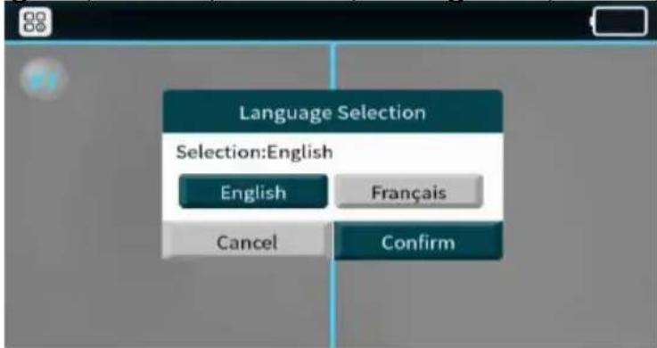
3. Initial Interface
◆ Language
Selection(English, French, German, Portuguese, Italian, Spanish)
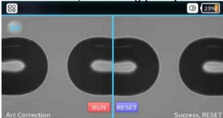
◆ First time ARC Correction(ARC correction could enhance the splicing performance and stability)
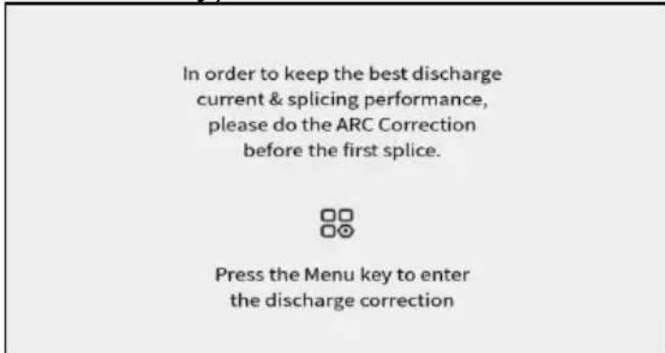
◆ ARC Correction Interface(Cutting and placing the fiber via correct way)
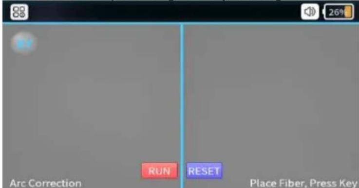
◆ ARC Correction Success(After “success” shows on screen, ARC correction process is done, then using [Rest] button to quit the mode.)
Function of Description
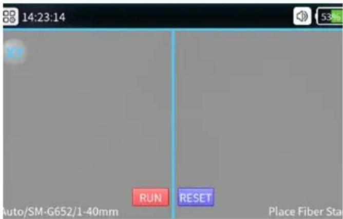
Fiber Observation Interface
Splicer Function Introduction Interface

System and Shortcut function settings
System Set Menu

| System set Explain | |
| Language Selection | English,French,German,Portuguese,Italian,Spanish |
| Time Setup Setting system time |
| Device Info Current device related information |
| Help Info Instruction manual |
| Reset Factory Setting Settings are renewed to factory settings |
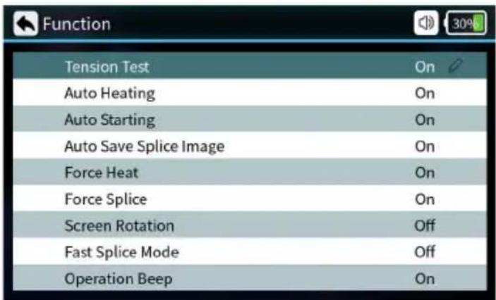
Shortcut function Menu
| Function | |
| Tension Test | On |
| Auto Heating | On |
| Auto Starting | On |
| Auto Save Splice Image | On |
| Force Heat | On |
| Force Splice | On |
| Screen Rotation | Off |
| Fast Splice Mode | Off |
| Operation Beep | On |
| Function Explain | |
| Tension Test | When it's on, the tension test will be executed automatically after splicing. |
| Auto Heating Put fiber into the heater, closing cover and automatic heating. | |
| Auto Starting When it's on, automatically splicing once cover closed. | |
| Auto Save Splice Image | When it's on, automatically saving splice picture. |
| Force Heat | When it's on, no fiber optic detected, pressing the heat button also heats it up. |
| Force Splice | When it's on, the user can press the start button to force the fusion splicing to continue, when the fusion splicing process detects an angle failure or fiber mismatch. |
| Screen Rotation | Screen interface rotated 180° |
| Fast Splice Mode | Can be set on or off, fusion time is reduced when fast mode is on. |
| Operation Beep Beeps can be set to be on or off. | |
1. Preparations Before Splice
Installing Fiber Sleeve

natural_image
Close-up of a hand holding a small metallic object against a plain background (no text or symbols visible)Install a sleeve on the fiber to protect the splice after splicing. Before installation, make sure that there is no dirt inside the sleeve, and hold the sleeve.
2. Stripping other protective layers except fiber coating
Stripping other protective and coating layer 40mm with a wire stripper.
natural_image
Close-up of a hand holding a black pen tip with three circular buttons (no text or symbols visible)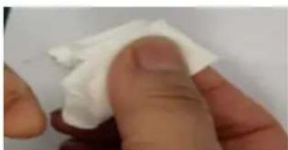
natural_image
Close-up of a finger holding a white cloth or paper, with no visible text or symbols.Clean Fiber
After stripping the optical fiber, use dust-free paper dipping with 99 % purity alcohol to clean the coating layer in a circular direction. Starting from the interface between the coating and the bare fiber, rotate the paper in the direction of the bare fiber in a circular direction and get rid of the debris of coating layers.
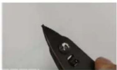
3. Fiber Cutting
(1) Open the Cleaver cover and place the fiber with clamp into the cleaving slot and keep the optical fiber vertical with the cleaver surface.
(2) Press forward the fiber clamp and ensure the forefront of the clamp lies closely with the cleaving slot. If not, the fiber can be longer than expected.
(3) Press down the fiber cover to cleave.
(4) Open the cover and take away the cleaved fiber.
(5) Take out the scrap and put into scrap box.
Attention: When cutting head face is not qualified or the cleaving cannot be down, please adjust the blade of cleaver.
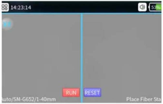
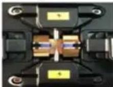
4. Fiber Placement
①Open the wind-proof cover and check if the V-groove is clean. If not please use air blow or blade to clean the V-groove.
②Put the cut fibers in the V-groove of the splicing modules and make sure the fibers are right in the V-groove.
③Check if the end-faces of the fibers are in the position between the electrode tips and the V-grooves. And make sure they're close to the electrodes tips. Or the fibers shall be re-placed.
④Close the wind-proof cover gently and start splicing.
5. Splicing and heating operations
Select the corresponding splicing program according to the type of fiber.
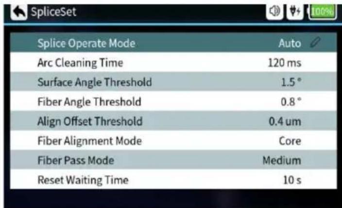
| Splice set Explain | |
| Splice Operate Mode | Automatic mode, semiautomatic mode, manual mode optional |
| Arc Cleaning Time | Clean discharge refers to the cleaning of fine dust adhering to the surface of an optical fiber by discharging the fiber prior to fusion splicing. |
| Surface Angle Threshold Limit | value of fiber end face angle |
| Fiber Angle Threshold | Angle limit after left and right fiber alignment |
| Alignment Offset Threshold | Limit of centre deviation after alignment of left and right fibers. |
| Fiber Alignment Mode | Core alignment, cladding alignment, and Fine alignment |
| Fiber Pass Mode Low, medium and high standards can be set. | |
| Reset Waiting Time | When the tensile test is turned on, waiting time for motor reset after opening the windproof cover. |
6. Splice program settings
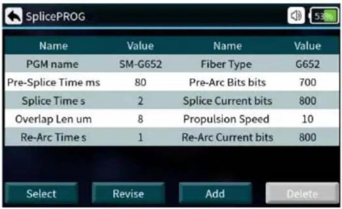
| Splice program Explain | |
| PGN name Name of splicer program |
| Pre-Splice Time ms Pre-Splice time can be set from: 0-500 (ms) |
| Splice time s Splice time can be set from:0-5 (s) |
| Overlap Len um Overlap Len can be set from:0-50 (um) |
| Re-Arc Time s Re-Arc Time can be set from:0-5 (s) |
| Fiber type Set fiber type |
| Pre-Arc Bits bits Pre-Arc current can be set from:0-4000 (bits) |
| Splice Current bits Splice Current can be set from:0-4000 (bits) |
| Propulsion Speed Propulsion Speed can be set from:0-50 (um/s) |
| Re-Arc Current bits Re-Arc Current can be set from:0-4000 (bits) |
7. Splice Process
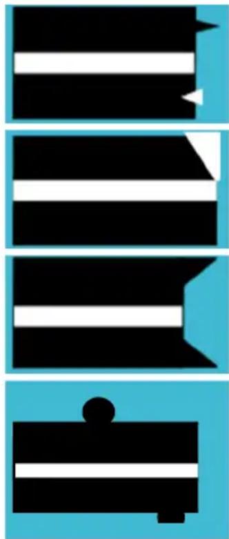
Close the windproof cover, and the fiber enters the automatic alignment state. The system will automatically check the end faces of fiber, if the end faces are not qualified the splicing will not be started and there will be error notice on the screen. The fiber needs to be cut again. If the forced splicing switch is turned on, the user can press the start button to continue splicing. If set to semi-automatic splicing, the screen will display angle information after fiber alignment. At this time, you can press the start button for arc splicing. If the detected angles exceed the limited angle there will be error notice on the screen. The fibers will need to be re-cut
| Displayed Images (X/Y Axis) | Explain Notice | Possible Reasons | Solutions |
 |
natural_image
Abstract geometric pattern with black and white horizontal stripes on blue background (no text or symbols)Angles of fiber, end-faces are not qualified
Problems with the fiber cutting process
Re-cut the fiber
8. Splice Loss Estimation and Quality Assessment
After the fiber splicing is completed, the evaluation value of the fiber splicing loss will be displayed on the right side of screen. The limit value of splice loss is set in the menu [splice set]. Note that the splice spot sometimes looks slightly thicker than the other fiber, which is a normal splicing situation and does not affect the splice loss.
Solutions of Abnormal Alignment Issues
| Phenomena Reason | Solutions | |
 Fiber core axis miss match Fiber core axis miss match | (1) Dust on V-groove or fiber pres ser foot(2) Image detection problem | (1) Clean V-groove and fiber presser foot(2) If it appears repeatedly, users need to do【Calibrate System】(3) Clean the lens and light source |
| Fiber core angle error | (1) Dust on V-groove or fiber pres ser foot | (1) Clean V-groove and fiber presser foot |
| (2) Poor fiber head face angle | (2) Re-cleave fiber | |
| (3) Fiber is placed incorrectly | (3) Replace fiber |
| air bubble | (1) Poor fiber head face angle(2) Dust on Fiber head face(3) Low Pre-splice current or short-time Pre-splice(4) Low splice current or short-time arc | (1) Re-cleave fiber(2) Re-clean fiber(3) Increase【Pre-splice Current】or【Pre-splice Time】(4) Increase【Splice Current】or【Splice Time】 |
| Fiber arc | (1) Splice propulsion force is not enough(2) Splice propulsion is too slow.(3) Spice current is too high or arc time is too long | (1) Do【Calibrate System】(2) Decrease【Pre-splice Current】or【Pre-splice Time】 |
| Too thick | The splice propulsion force is excessive | Decrease【Overlap Length】,then do【Arc Calibration】test |
| meticulous | (1) The splice propulsion force is not enough(2) Splice current is excessive | (1) Increase【Overlap Length】,then do【Arc Calibration】test(2) Decrease【Splice Current】 |
| Slit | Splice current is too small | Increase【Splice Current】 |
9. Tension Test
If "Tension Test" sets "ON", after splicing, tension test will automatically be performed and the pulling force is 2N.
10. Storage and query of splicing results
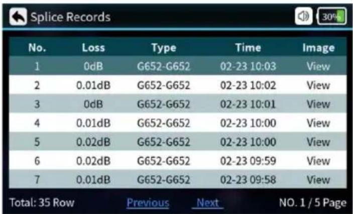
| Splice record Explain | |
| No Sort by splicing time | |
| Loss Fiber loss after splicing | |
| Type Types of fiber for splicing | |
| Time Splice time | |
| Image Viewable image of the finished splice |
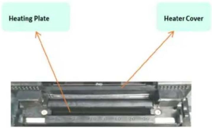
11. Heater operation
Select [Heat Program] in the main menu, select the corresponding heating program according to the diameter and length of the heat shrink tube, and try to use the preset heating parameters. Because of the difference in environment, the heating temperature and time can be adjusted.
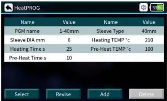
| Heat PROG | Explain |
| Heating PN | There are many heating programs for different shrinkable tubes stored in the system, also many self-set programs are offered to users. |
| Sleeve DIA | 1-20mm |
| Heating Time | Heat shrink heating time. |
| Pre-Heat Time | Pre-heating time |
| Sleeve Type | 10mm-60mm normal tube, FC, SC |
| Heating Temp | The temperature limit of heating process. |
Pre-Heat Temp
The temperature limit of preheating process.
1.Open the heater cover.
2. Take out the spliced optical fiber, and move the heat shrinkable tube to the center of the spliced point.
3. Put the protective sleeve into the heater, straighten the optical fiber gently, and put the sleeve protective sleeve into the center of the sleeve, then cover the heater cover, and the heating indicator lights up.
4. After the heating operation is completed, the heating indicator light is off; at this time, the heater cover needs to be opened immediately to take out the optical fiber. (Note: Do not touch the heated heat-shrinkable protective sleeve with your hands to prevent burning)
5. Check the heat-shrinking effect, if it is qualified, put it into the cooling plate for natural cooling; if it is unqualified, if there is dust or air bubbles inside, it is recommended to perform the heat-shrinking operation again.
Maintenance
Equipment maintenance menu
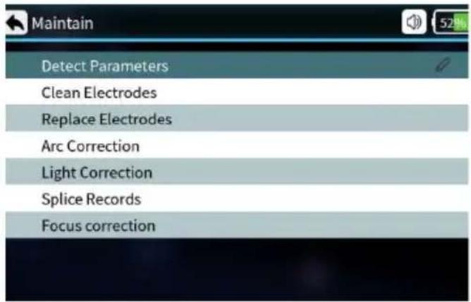
| Equipment Maintenance | Explain |
| Detect Parameters | Automatic self-inspection of electrode position, motor and other system parameters |
| Clean Electrodes | Multiple high-current discharges to clean the electrodes. |
| Replace Electrode | After replacing the electrode, the discharge position is automatically determined and the electrode is stabilized by multiple discharges |
| ARC Correction Performs Arc Correction operation and automatically corrects the discharge current. | |
| Light detection Automatic calibration of red light sources | |
| Splice Records Query splice time, estimate loss, image, etc. | |
| Focus Correction Automatic calibration of fiber focus on screen. | |
1. ARC Calibration
The steps of ARC calibration operation are as follows:
(1) Select [ARC Correction] in the [Maintenance] menu.
(2) Put the cut fiber into the fusion splicer and close the windproof cover.
(3) Press the start key to execute.
(4) If the display prompts "ARC current is too large" or "ARC current is too small", please continue to repeat the operations described in (2) and (3) above until it prompts that the discharge calibration is successful.
(5) If it prompts "discharge calibration failed", please start step (1) again.
Suggestion: when the type of fusion splicing fiber is changed; when the system is upgraded; when the temperature, humidity, and air pressure of the operating environment change greatly; continuous splicing failure or high loss; the fusion splicer has not been used for a long time, or the electrodes have been used too many times; Perform ARC correction after cleaning or replacing the electrode, otherwise it will affect the splicing effect.
2. Electrode maintenance
Clean electrode
(1) Select [Clean Electrodes] in the [Maintenance] menu.
(2) Press the start button, and the machine will automatically clean the electrodes.
Note: Do not touch the tip of the electrode with hard objects to avoid damage to the electrode and affect the splicing effect.
Replace electrode
The electrode will wear out due to use, please replace the electrode in time, otherwise it will affect the fusion effect of the optical fiber. The number of discharges needs to be reset after replacing the electrodes. Do not touch the electrode tip when replacing.
(1) Before replacing the electrode, the user needs to turn off the power.
(2) Loosen the screws fixed on the electrode cover and remove the electrode.
(3) Install the new electrode into the electrode slot, install the electrode cover, and slowly tighten the screws.
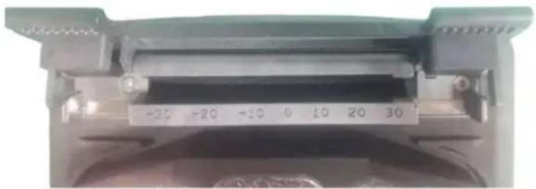
(4) Observe whether the connecting lines of the two electrodes are in the horizontal plane and in the vertical plane; if not, please reinstall.
3. System parameter self-check test
Strongly recommended that the fusion splicer perform system parameter self-test after system upgrade; replace electrodes or move electrodes; the fusion splicer has undergone long-distance transportation or severe vibration; Will affect the splicing effect.
The steps of system parameter self-test are as follows:
(1) Clean the V-groove with a cotton swab dipped in alcohol, and clean the prepared optical fiber.
(2) Select [Detect Parameter] in the [Maintenance] menu, and press the menu key to enter the system parameter self-test interface.
(3) Put the cut optical fiber into the fusion splicer, close the windproof cover, and press the start button to start the system parameter self-test.
(4) Under normal circumstances, the parameter self-test will last for about 2 minutes, please observe the prompt information on the LCD screen, if the self-test fails, please correct the operation according to the prompt information, and restart the system parameter self-test (step (2)).
4. Cleaning and maintenance of Splicing machine
Cleaning the V-groove
If there is contaminant in V-groove the fibers will deviate from normal position and thus the alignment will be affected so that the splicing loss may be abnormally higher. So users must check and clean V-groove regularly. The operations are as below:
(1) Open the wind-proof cover.
(2) Clean the contaminant on V-groove with equipped dust blower.
(3)Clean the bottom of the V-groove with cotton swab dipped with alcohol.
Notice: Do not touch the tips of electrodes. Clean the V-groove gently and do not use any hard stuff (Blade etc.) to clean the groove in case any damages affecting normal functions caused.
natural_image
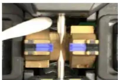
Close-up of a mechanical component with internal parts and a white tool, no visible text or symbolsCleaning the fiber presser pin
Dust on fiber pressers may cause fiber fixing or fiber holding issues and it will directly affect splicing quality. Users shall check and clean the fiber pressers regularly.
- Open the wind-proof cover.
- Clean the surface of the pressers with a fine cotton swab dipped with alcohol, dry the presser with a dry cotton swab after cleaning.
natural_image
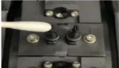
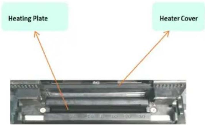
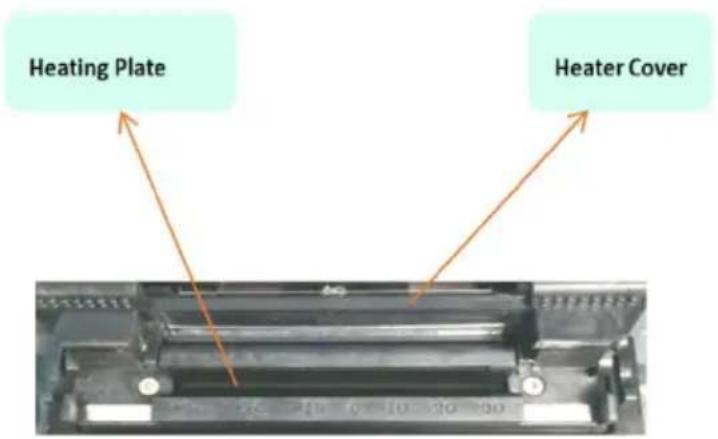
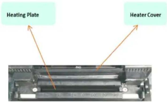
Close-up of a mechanical component with four ports and a white tool inserted (no visible text or symbols)Cleaning the heater
Dust and dirt are easy to deposit on the heater, please clean the heating plate regularly with a dry cotton swab.
5. Software upgrade
(1) In the [System] menu, enter the query page of [Machine Information], and you can view the version number of the current fusion splicer (such as V1.0.0 / V1.0.0).
(2) Obtain the latest upgrade file from the fusion splicer manufacturer, and compare whether the current version is consistent. If the version number is completely consistent, there is no need to upgrade again.
(3) Turn on the fusion splicer, connect the computer and the fusion splicer with a USB data cable, and you will find that the U disk operation prompt pops up on the computer. Copy the upgrade file directly to the root directory of the U disk, shut down and restart. (Note: Be sure to shut down the computer after the file is copied, and unplug the USB data cable, otherwise there will be abnormal situations.)
(4) After restarting the fusion splicer, please operate according to the prompt information. Press the menu item to enter [System Settings] -> [Machine Information], the fusion splicer will automatically detect the upgrade file and automatically upgrade, wait for the fusion splicer to automatically update and restart automatically, that is, the entire software upgrade process is over, if there is an abnormal interruption, please Repeat steps (2) (3) (4) again. If you encounter problems that cannot be solved, please contact after-sales maintenance.
Others
| Warning information | Reason Countermeasures | |
| Incorrect placement of left fiber (LFPC) | (1) Left fiber is cleaved too short; (2) The part of left fiber put into V-groove is broken; (3) Left fiber is not put into the center of V-groove; Left propulsion equipment is incorrectly connected | In the case of 1 or 2,re-cleave left fiber and make sure the cleaved length is appropriate In the case of 3, replace left fiber If the breakdown do not match 1、2、3,do【Calibrate System】, If the problem remains, please contact the after sales service department |
| Right fiber placement is incorrect (RFPC) | (1) Right fiber is cleaved too short; (2) The part of Right fiber put into V-groove is broken; (3) Right fiber is not put into the center of V-groove; Right propulsion equipment is incorrectly connected | Solutions refer to the above |
| Left and Right fiber placement are incorrect (LRFPC) | The same as above Solution refer to the above | |
| Left fiber is Unqualified (LFNQ) | (1) Left fiber surface is dusty; (2) Left fiber is cleaved poorly, such as core defect, cladding defect or fiber incompleteness | In the case of 1,use alcohol to clean the left fiber In the case of 2,remake fiber |
| Right fiber is unqualified (RFNQ) | (1) Right fiber surface is dusty (2) Right fiber is cleaved poorly, such as core defect,cl adding, defect, fiber incompleteness | Solution refer to the above |
| Left and Right fiber is unqualified (LRFNQ) | The same as above Solution refer to the above | |
| Left fiber head face is unqualified (LFEANQ) | Left fiber head face angle exceeds limit | Re-cleave left fiber. If cutting quality is still poor after multiple trial , replace the blade (attention: in 【Menu】->【Splicing Mode】->【Surface Angle Threshold】,head face angle limit can be set) |
| Right fiber head face is unqualified (RFEANQ) | Right fiber head face angle exceeds limit | Solution refer to the above |
| Left and Right fiber head face are unqualified | Left and Right fiber head face angle exceeds limit | Solution refer to the above |
| Unqualified fiber angle | The angle errors of the optical fibers on both sides in the horizontal and vertical directions are greater than the set threshold. | Reposition the fiber optics on both sides. |
| Estimated loss amount is too much | (1) splice loss exceeds limit; (2) The selected program do not match the fiber type | Clean v-groove, re-operate 【Arc calibration】then splice again |
| Power is too insufficient | Current remaining battery less than 2% | Use power adapter to charge |
| Replace electrodes | Electrodes arc recordsexceed the limit | Replace electrodes(operate【Replace Electrodes】,【Calibrate system】) |
| arc soundsabnormally | Electrodes are incorrectlyplaced | Re-install electrode strictly |
| arc delay or systemcould not arc | (1)Electrodes are incorrectlyplaced;(2)The electrode tip iswrapped by monox | (1)Re-install electrode strictly;(2)Clean electrode tip or replaceelectrode |
| system crasheswhen arc | Electrodes are incorrectlyplaced | Re-install electrodes strictly |
| Arc calibrationfailure | EnvironmentAffects arc greatly | If the system warns that arc currentis too big, decrease splice current,then do【Arc calibration】and vice versa.If the problem remains, contact theafter sales service department |
| Optical fiberalignment error | (1) Microscope lens, LEDlamp or V-groove is dusty;(2) Equipment power systemis faulty | Clean the microscope lens,LED lamp and V-groove, if the problem remains, contact the after sales servicede department |
| Fiber spliced joint's quality is poor | (1) Fiber is dusty; (2) The fiber type or fusion splice program selected is wrong; (3) Fusion splice environment changes greatly; (4) Control equipment is broken | (1) Re-make optical fiber, splice again; (2) Choose the right type of fiber and fusion splice program; (3) Operate【Arc calibration】to obtain the appropriate intensity of arc; (4) Operate【Calibrate System】 |
| The keyboard has no response | System crashes Turn off the power and restart | |
| The screen has no light or blurry colors | (1) System crashes; (2) Wire of LCD monitor looses or is broken | Turn off the power and restart. If the problem remains, contact the after sales service department |
| On both sides of fiber after discharge, splicing has not succeeded | Abnormal discharge intensity or system error | Please do continue to splice again after discharge correction, if still can not solve the problem, then shutdown and restart |
| Optical fiber in the process of alignment is beyond the view outside | 1.Optical fiber placed outside the V groove;2.System is running abnormal | 1.Please re-position the optical fiber and guarantee in the center of the V groove2.The selected splicing mode ->【splicing operation mode】menu, enter the "manual" mode, select operation about optical fiber, the operator can be through four direction key move the corresponding side of the optical fiber, motor back to the center of the field, and then do self-checking system parameters. |
After-Sales Service card
Name: ____
Tele:
Product S/N No. : ____
Product Model: ____
Address:
purchasing office:
Description of the problem:
Note
We are constantly improving and design and specifications are subject to change without notice.
All information in this manual has been carefully proofread for accuracy and we reserve the right to explain any typographical errors or omissions.
Legal Notices
◆ Without literal authorization from our company, any organizations or individuals shall not extract, copy part or all of the contents of the manual and shall not be disseminated in any form.
This manual describes the product and the features or functions of its accessories are determined by production batches. Thus the product or its accessories described in the manual may not be the same with the ones you purchased. The manufacturer keeps the right of amending the manual whenever it's necessary without formal notice and shall take no responsibility for such actions.
◆ Notice: Please thoroughly read the instruction manual to operate the splicer more accurately and professionally.
Manufacturer: Shanghaimuxinmuyeyouxiangongsi
Address: Shuangchenglu 803nong11hao1602A-1609shi, baoshanqu, shanghai 200000 CN.
Imported to AUS: SIHAO PTY LTD. 1 ROKEVA STREETEASTWOOD NSW 2122 Australia
Imported to USA: Sanven Technology Ltd. Suite 250, 9166 Anaheim Place, Rancho Cucamonga, CA 91730
| EC | REP |
E-CrossStu GmbH
Mainzer Landstr.69, 60329 Frankfurt am Main.
| UK | REP |
YH CONSULTING LIMITED.
C/O YH Consulting Limited Office 147, Centurion
House, London Road, Staines-upon-Thames, Surrey,
TW18 4AX
VEVOR®
TOUGH TOOLS, HALF PRICE
Technical Support and E-Warranty Certificate
www.vevor.com/support
VEVOR®
TOUGH TOOLS, HALF PRICE
natural_image
Black electronic device with visible ports and buttons, no readable text or symbolsBEHÖVER HJÄLP? KONTAKTA OSS!
2. Tangentbord

4. Värmare
Basic Operation
Function of Description
natural_image
Close-up of a hand holding a pen, no visible text or symbolsnatural_image
Close-up of a hand holding a black pen tip with three small circular indentations (no text or symbols visible)
natural_image
Close-up of a finger holding a white cloth or paper, with no visible text or symbols.Ren Fiber
natural_image
Close-up of a mechanical component with a central scale and mounting holes (no visible text or symbols)natural_image
Interior view of a vehicle showing internal components with no visible text or symbolsnatural_image
Close-up of a mechanical component with a white tool inserted, showing no visible text or symbols.C/O YH Consulting Limited Office 147, Centurion House, London Road, Staines-upon-Thames, Surrey TW18 4AX
VEVOR®
TOUGH TOOLS, HALF PRICE
www.vevor.com/support
VEVOR®
TOUGH TOOLS, HALF PRICE
natural_image
Black electronic device with visible ports and buttons, no readable text or symbolsPOTRZEBUJESZ POMOCY? SKONTAKTUJ SIE Z NAMI!
2. Klawiatura

4. Podgrzewacz
©
Function of Description
natural_image
Close-up of a hand holding a pen, no visible text or symbolsnatural_image
Close-up of a black pen tip with two small metallic clips, held by a finger (no text or symbols visible)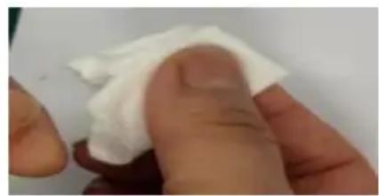
natural_image
Close-up of a finger holding a white cloth or paper, with no visible text or symbols.Czyste włókno
natural_image
Pure mechanical assembly diagram without any text, numbers, or symbolsnatural_image
Simple black-and-white icon of a rectangular object with a horizontal line and a circular top, set against a solid blue background (no text or symbols)natural_image
Close-up of a mechanical component with blue and yellow components, no visible text or symbolsnatural_image
Close-up of a mechanical component with a white tool inserted, showing multiple black components and small bolts (no visible text or symbols)C/O YH Consulting Limited Office 147, Centurion House, London Road, Staines-upon-Thames, Surrey TW18 4AX
VEVOR®
TOUGH TOOLS, HALF PRICE
www.vevor.com/support
VEVOR®
TOUGH TOOLS, HALF PRICE
natural_image
Black electronic device with visible ports and buttons, no readable text or symbols2. Tastatur
4. Heizung
Basic Operation
Function of Description
natural_image
Close-up of a hand holding a pen, no visible text or symbolsnatural_image
Close-up of a hand holding a black pen tip with metallic rivets (no text or symbols visible)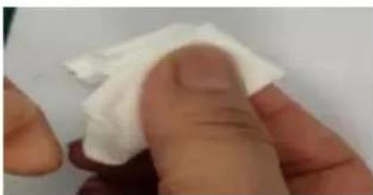
natural_image
Close-up of a finger holding a white cloth or paper, with no visible text or symbols.Saubere Faser
natural_image
Close-up of a mechanical or electronic component with no visible text, numbers, or symbols.natural_image
Interior view of a vehicle showing internal components with no visible text or symbolsnatural_image
Close-up of a black electrical switch component with four terminals and a white tool inserted (no visible text or symbols)5. Software -Upgrade
C/O YH Consulting Limited Office 147, Centurion House, London Road, Staines-upon-Thames, Surrey TW18 4AX
VEVOR®
TOUGH TOOLS, HALF PRICE
www.vevor.com/support
VEVOR®
TOUGH TOOLS, HALF PRICE
natural_image
Black electronic device with visible ports and buttons, no readable text or symbolsBESOIN D'AIDE? CONTACTEZ-NOUS!
2. Clavier

4. Chauffage
5. Interface externe
Basic Operation
Function of Description
natural_image
Close-up of a hand holding a pen, no visible text or symbolsnatural_image
Close-up of a black pen tip with two small metallic buttons on the tip, held by a finger (no text or symbols visible)
natural_image
Close-up of a hand holding a white cloth or paper over a red object (no visible text or symbols)Fibres propres
natural_image
Close-up of a mechanical or electronic component with no visible text, numbers, or symbols.natural_image
Two abstract black-and-blue shapes with white horizontal stripes and a small circular element, no text or symbols present.natural_image
Abstract graphic with two black rounded shapes on a light blue background (no text or symbols)natural_image
Abstract black and white horizontal bar design on a light blue background (no text or symbols)natural_image
Close-up of a mechanical component with no visible text or symbols on its body, numbers, or symbols.natural_image
Close-up of a mechanical component with internal components and a white tool, no visible text or symbolsnatural_image
Close-up of a mechanical component with a white tool inserted, showing no visible text or symbols.C/O YH Consulting Limited Office 147, Centurion House, London Road, Staines-upon-Thames, Surrey TW18 4AX
VEVOR®
TOUGH TOOLS, HALF PRICE
natural_image
Black electronic device with visible ports and buttons, no readable text or symbolsHULP NODIG? NEEM CONTACT MET ONS OP!
2. Toetsenbord
4. Verwarming

5. Buiteninterface

Basic Operation
Function of Description
Fiber-observatie-interface
| Function | |
| Tension Test | On |
| Auto Heating | On |
| Auto Starting | On |
| Auto Save Splice Image | On |
| Force Heat | On |
| Force Splice | On |
| Screen Rotation | Off |
| Fast Splice Mode | Off |
| Operation Beep | On |
natural_image
Close-up of a hand holding a pen, no visible text or symbolsnatural_image
Close-up of a black pen tip with a small metallic droplet and 'E' label, held by a finger (no other text or symbols visible)
natural_image
Close-up of a finger holding a white cloth over a red object (no text or symbols visible)Schone vezels
natural_image
Interior view of a vehicle showing internal components with no visible text or symbolsvan de vezelperspen
natural_image
Close-up of a mechanical component with a white tool inserted, showing no visible text or symbols.De kachel schoonmaken
5. Software -upgrade
C/O YH Consulting Limited Office 147, Centurion House, London Road, Staines-upon-Thames, Surrey TW18 4AX
VEVOR®
TOUGH TOOLS, HALF PRICE
www.vevor.com/support
VEVOR®
TOUGH TOOLS, HALF PRICE
natural_image
Black electronic device with visible ports and buttons, no readable text or symbols2. Teclado

4. Calentador
5. Interfaz externa

Basic Operation
Function of Description
| Function | |
| Tension Test | On |
| Auto Heating | On |
| Auto Starting | On |
| Auto Save Splice Image | On |
| Force Heat | On |
| Force Splice | On |
| Screen Rotation | Off |
| Fast Splice Mode | Off |
| Operation Beep | On |
natural_image
Close-up of a hand holding a pen, no visible text or symbolsnatural_image
Close-up of a black pen tip with metallic screw and three silver clips (no text or symbols visible)
natural_image
Close-up of a finger holding a white cloth or paper, with no visible text or symbols.Fibra limpia
natural_image
Close-up of a mechanical or electronic component with no visible text, numbers, or symbols.natural_image
Abstract graphic with a black horizontal bar and white circular element on a solid blue background (no text or symbols)
natural_image
Abstract graphic with a black horizontal bar and white circular element on a solid blue background (no text or symbols)
natural_image
Abstract graphic with a blue rectangle and black horizontal bar, featuring a white dot (no text or symbols)
natural_image
Abstract graphic with a blue rectangle and black horizontal bar, featuring a white dot (no text or symbols)[Non-Text]
[Non-Text]
[Non-Text]
[Non-Text]
[Non-Text]
[Non-Text]
[Non-Text]
[Non-Text]
[Non-Text]
[Non-Text]
[Non-Text]
[Non-Text]
[Non-Text]
[Non-Text]
[Non-Text]
[Non-Text]
[Non-Text]
[Non-Text]
[Non-Text]
[Non-Text]
[Non-Text]
[Non-Text]
[Non-Text]
[Non-Text]
[Non-Text]
[Non-Text]
[Non-Text]
[Non-Text]
Burbuja de aire
m = 311
m = 311
m = 311
m = 311
m = 311
m = 311
m = 311
m = 311
m = 311
m = 311
m = 311
m = 311
The Ground Truth image displays a single, solid horizontal line. According to Rule 2 (UNDERSCORE & LINE RULES), this is a stylistic or background line, not a placeholder underscore. Therefore, the OCR result must ignore it and output nothing or only meaningful text. The provided OCR content is "____", which consists of four underscores. This is an incorrect interpretation of the line as a placeholder, violating the rule that stylistic lines must be ignored. The OCR has hallucinated underscores where none should exist based on the GT's visual context. Hence, the OCR result is inconsistent with the Ground Truth.
m = 311
m = 311
m = 311
m = 311
m = 311
m = 311
m = 311
m = 311
natural_image
Close-up of a mechanical component with a central scale and green housing (no visible text or symbols)natural_image
Close-up of a mechanical component with blue and yellow components, no visible text or symbolsnatural_image
Close-up of a mechanical component with a white tool inserted, showing four black components and a small metallic bolt (no visible text or symbols)C/O YH Consulting Limited Office 147, Centurion House, London Road, Staines-upon-Thames, Surrey TW18 4AX
VEVOR®
TOUGH TOOLS, HALF PRICE
natural_image
Black electronic device with visible ports and buttons, no readable text or symbols2. Tastiera

4. Stufa

5. Interfaccia esterna
Basic Operation
Function of Description
| Function | |
| Tension Test | On |
| Auto Heating | On |
| Auto Starting | On |
| Auto Save Splice Image | On |
| Force Heat | On |
| Force Splice | On |
| Screen Rotation | Off |
| Fast Splice Mode | Off |
| Operation Beep | On |
natural_image
Close-up of a hand holding a pen, no visible text or symbolsnatural_image
Close-up of a black pen tip with metallic screw and letter 'IE' on the tip, held by a finger (no text or symbols visible)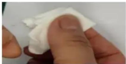
natural_image
Close-up of a finger holding a white cloth over a small object (no text or symbols visible)Fibra pulita
natural_image
Pure mechanical assembly diagram without any text, numbers, or symbolsnatural_image
Abstract graphic with a black horizontal bar and white circular element on a cyan background (no text or symbols)natural_image
Close-up of a mechanical component with blue and yellow components, no visible text or symbolsnatural_image
Close-up of a mechanical component with a white tool inserted, showing bolted components (no visible text or symbols)Importato in AUS: SIHAO PTY LTD. 1 ROKEVA STREETEASTWOOD NSW 2122 Australia
Importato negli USA: Sanven Technology Ltd. Suite 250, 9166 Anaheim Place, Rancho Cucamonga, CA 91730
| EC | REP |
E-CrossStu GmbH
Mainzer Landstr.69, 60329 Frankfurt am Main
| UK | REP |
YH CONSULTING LIMITED.
C/O YH Consulting Limited Office 147, Centurion House, London Road, Staines-upon-Thames, Surrey TW18 4AX
VEVOR®
TOUGH TOOLS, HALF PRICE