ALK-T3 - Fiber fusion tool Vevor - Free user manual and instructions
Find the device manual for free ALK-T3 Vevor in PDF.

| Brand | Vevor |
| Model | ALK-T3 |
| Product Type | Fusion Splicer for Optical Fiber |
| Dimensions (approx.) | 160 x 170 x 140 mm |
| Weight | 2.8 kg |
| Power Supply | Lithium battery 10.9 V / 7800 mAh; AC adapter 220 V AC; car charger 12 V DC |
| Battery Life | About 260 splices + heating per charge |
| Charging Time | 3 hours |
| Supported Fiber Types | SM, MM, DS, NZDS, UI, BUI, EDF (single-mode, multi-mode, etc.) |
| Fiber Diameter | Coating: 80-150 µm; Cladding: 100-1000 µm |
| Alignment Mode | Core, cladding, fine (selectable) |
| Average Splice Loss | 0.03 dB (SM), 0.02 dB (MM), 0.05 dB (DS, NZDS) |
| Splice Time | 7 s (fast mode) / 9 s (standard mode) |
| Display | 5-inch color LCD touchscreen |
| Magnification | 210x to 320x (zoom up to 1100x after splicing) |
| Tensile Test | ≥ 2 N (optional) |
| Tube Heating | Diameters 2-6 mm; time 10-23 s; temperature up to 260 °C |
| Memory | 100,000 splice records, 10,000 images |
| Main Functions | Auto alignment, arc correction, auto heating, auto start, image saving |
| Recommended Maintenance | Cleaning of V-grooves, lenses, clamps; electrode replacement after 5000 discharges |
| Safety | Internal high voltage; do not disassemble; use original accessories; avoid liquids and dust |
| Spare Parts Available | Electrodes, battery, AC adapter, car charger, fiber cleaver |
| Repairability | Electrode replacement by user; professional maintenance recommended |
| Compliance | FCC Part 15, European Directive 2012/19/EU (WEEE) |
| Warranty | Electronic warranty certificate at www.vevor.com/support |
Frequently Asked Questions - ALK-T3 Vevor
User questions about ALK-T3 Vevor
0 question about this device. Answer the ones you know or ask your own.
Ask a new question about this device
Download the instructions for your Fiber fusion tool in PDF format for free! Find your manual ALK-T3 - Vevor and take your electronic device back in hand. On this page are published all the documents necessary for the use of your device. ALK-T3 by Vevor.
USER MANUAL ALK-T3 Vevor
Technical Support and E-Warranty Certificate www.vevor.com/support
OPTICAL FIBER FUSION SPLICER MODEL:ALK-T3
We continue to be committed to provide you tools with competitive price. "Save Half", "Half Price" or any other similar expressions used by us only represents an estimate of savings you might benefit from buying certain tools with us compared to the major top brands and does not necessarily mean to cover all categories of tools offered by us. You are kindly reminded to verify carefully when you are placing an order with us if you are actually Saving Half in comparison with the top major brands.
VEVOR®
TOUGH TOOLS, HALF PRICE
OPTICAL FIBER FUSION
SPLICER
MODEL: ALK-T3

natural_image
Close-up of a black optical fiber optic switch with control buttons and a blue base (no visible text or symbols)NEED HELP? CONTACT US!
Have product questions? Need technical support? Please feel free to contact us:
Technical Support and E-Warranty Certificate www.vevor.com/support
This is the original instruction, please read all manual instructions carefully before operating. VEVOR reserves a clear interpretation of our user manual. The appearance of the product shall be subject to the product you received. Please forgive us that we won't inform you again if there are any technology or software updates on our product.

Warning:
Please strictly follow the safety guidance of the manual in application of the optical fiber fusion splicer(Hereinafter referred to as Splicer). The ignorance or violence of the rules or notice stressed in the manual may cause electric shock, fire disaster and injuries to users. The manufacturer shall take no responsibilities of accidents caused by improper use.
- The input voltage of this model of machine is definite; please do not use the voltage outside the scope. Please use the correct AC and DC power supply.
- When the fusion splicer comes across the following failures, please immediately remove the AC power cord from the power supply input and turn off the fusion splicer, otherwise will lead to the incapable of the repairing and even will cause personal injury, death and fire.
★ Smoke, smell, noise or heat anomaly
★ Broken or damaged machines
★ Liquid or foreign matter enters the interior of the machine
- This model of fusion splicer does not have the need to maintain internal components, dismantling of fusion splicer and power modules is prohibited; any mistake in maintenance will lead to the machine beyond repair even causing bodily harm.
- The machine has strictly limitation to the power supply module used.
- The fusion splicer is prohibited to be used under the environment with the inflammable liquid or flammable gas; otherwise will lead to fire, explosion and other serious consequences.
- Disclaimer Clause
The Company does not assume any liability for all damage caused by the use of non original battery.
- To avoid possible wrong operation or insecurity, a valid ground three-hole socket must be used when AC/DC adaptor access to AC 220V 50HZ power.
CORRECT DISPOSAL

This product is subject to the provision of European Directive 2012/19/EC. The symbol showing a wheelie bin crossed through indicates that the product requires separate refuse collection in the European Union. This applies to the product and all accessories marked with this symbol. Products marked as such may not be discarded with normal domestic waste, but must be taken to a collection point for recycling electrical and electronic devices
BATTERY DISPOSAL

To minimize hazards to health and the environment at the end of this product's life, laws dealing with Waste Electrical and Electronic Equipment (WEEE) and The Waste Battery Directive require you to dispose of this product at a suitable collection facility where it will be sent in order to remove the batteries and for appropriate recycling. Please contact your local authorities for more details on recycling and safe disposal of these in your area.
FCC INFORMATION
CAUTION: Changes or modifications not expressly approved by the party responsible for compliance could void the user's authority to operate the equipment!
This device complies with Part 15 of the FCC Rules. Operation is subject to the following two conditions:
1) This product may cause harmful interference.
2) This product must accept any interference received, including interference that may cause undesired operation.
WARNING: Changes or modifications to this product not expressly approved by the party. Responsible for compliance could void the user's authority to operate the product.
Note: This product has been tested and found to comply with the limits for a Class B digital device pursuant to Part 15 of the FCC Rules, These limits are designed to provide reasonable protection against harmful interference in a residential installation.
This product generates, uses and can radiate radio frequency energy, and if not installed and used in accordance with the instructions, may cause harmful interference to radio communications. However, there is no guarantee that interference will not occur in a particular installation. If this product does cause harmful interference to radio or television reception, which can be determined by turning the product off and on, the user is encouraged to try to correct the interference by one or more of the following measures.
- Reorient or relocate the receiving antenna.
- Increase the distance between the product and receiver.
- Connect the product to an outlet on a circuit different from that to which the receiver is connected.
- Consult the dealer or an experienced radio/TV technician for assistance.
1. Working Environment
1.1 Cautions for use/storage of the splicer:
● Working Temperature: -10^ +45^
● Temperature Limitation: -20^ +55^
● Working Humidity: ≤95%RH (No condensation)
● Maximum Wind Speed: 15m / s
- Storage Conditions: - 10°C \~ +45°C (With Battery, No Condensation)
-20°C + 60°C (No Battery, No Condensation)
Don't use the splicer in environment vulnerable to fire, explosion in case any fire disaster or explosion caused.
Don't use or store the splicer in environment of high temperature or high humidity in case any damages to the machine caused. When the splicer is moved from low temperature environment to environment of higher temperature please take possible warming up measures to eliminate condensation.
Please take suitable dust-resistance measures when using the machine in dusty environment to prevent lots of dust getting into the machines and causing device malfunction.
2. Power Supply
Please use the matching accessories of the splicer and don't use any power adapter, battery or power cord that are not specified in the instruction.
Please don't use the splicer under the voltages that are not specified for the model in case any fire disasters or electric shock caused. The customized car charger power cord is only available for 12V power supply of gasoline cars. In any circumstances, users shall not use it on diesel car with 24V power supply.
3. Battery
Please strictly follow the instructions when using the battery. Improper use of battery may cause battery heating up, burst, explosion, fire disaster or injuries to users.
Please do not charge the battery with methods that are not specified in the manual.
Do not dispose the battery in fire.
Do not reverse the positive and negative poles.
Do not expose the discharging battery under sunshine or in environment with high temperature or in fire.
Do not throw or strike on the battery.
If the battery electrolyte leaks out, please handle it carefully. If user's skin or eyes are contaminated by electrolyte accidentally, please wash it thoroughly and look for medical help immediately. At the same time please inform the after-sales department to handle the battery.
4. Other Cautions
Please prevent any liquid or metal materials getting into the internal structure of the product, or possible fire, electric shock or product malfunction may be caused. Once water or any metal materials get into the
product please stop using, cut the power supply, turn off the equipment and contact the maintenance service department.
Please do not touch the electrodes when the equipment is working in case getting hurt by the high voltage. Please do cut the power supply and turn off the equipment before changing electrodes.
Do not disassemble or demolish the splicer, its battery or its adapter in case overheating, burst or fire disaster caused.
Except the components that are allowed to be changed in this manual please do not try to demolish any parts of the splicer. The maintenance or repair of the equipment must be operated by professional technicians from our company, improper operations may cause fire or electric shock.
Do not touch the shrinkable tube in heating process or when it's just finished, as the shrinkable tube is very hot and may cause scald.
Do not touch the splicer, power cord or power plug with wet hands in case electric shock caused.
Do not clean the microscope lens, V groove, screen etc with any chemical materials except alcohol. Otherwise it may cause image blur or spots on screen, or may even cause corrosion or damage of the equipment.
Please prevent the equipment from strong shaking or crash, or the equipment may be damaged. Please transport or store the splicer by dedicated carrying box.
Please do entire machine maintenance once a year to maintain the performance of the splicer.
Production Introduction
Optical Fiber Fusion Splicer is mainly used for optical fiber cable maintenance and relative operations. Thus it is also called fiber cable splicer. It is a device that uses high precision propulsion structure to push two fibers to get closer to each other and uses an electric arc to melt two optical fibers together at their end faces, to form a single long fiber.
Optical fiber fusion splicers are mainly applied by : Telecom carriers, ISP, network project contractors, laboratories. And they're applied in : Fiber cable network maintenance, telecom projects, emergent repairing, optical experiments, manufacture and testing of optical devices, academic researches in colleges.
- Introduction of Function Buttons
| Appearance | Name | Function |
 | Menu / Confirm | Enter menu page/Confirm or save |
 | Power On / Off | Turn on/off the power |
 | Next | Switch to next option/Switch X/Y views |
 | Return / Reset | Return/Reset the motor |
 | Start / + | Run to start splicing/Adjust parameters(Increase/Switch) |
 | Heating | Start heating |
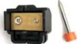
- Description of product structure
| Appearance | Name | Function | |
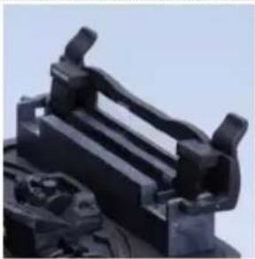 | Heater | For heating process of shrinkable tubes after splicing. | |
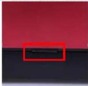
natural_image
Close-up of a black surface with a red rectangular highlight (no text or symbols)Battery Fixing Button
Put on/take off the battery
3. Fundamental Parameters
● Applicable Optical Fibers: SM, MM, DS, NZDS, UI, BUI, EDF, etc
● Applicable Core Type : Single Core
- Motor : 4 Motors
● Applicable Fiber diameter: Cladding diameter 80-150μm, Coating diameter 100-1000μm
Splicing Mode
● Pre-store: 18 groups. Customize: 982groups
- Splicing Results Recording: 100,000-group splicing records & 10,000 image storage
● Splicing Speed: 9SEC(Standard Mode) 7SEC (Fast Mode)
- Alignment: Clad to clad alignment
Splicing Loss
● Average Splicing Loss: 0.03dB(SM), 0.02dB(MM), 0.05dB(DS), 0.05dB(NZDS)
- Return Loss: ≥60dB
- Splicing Loss Estimation: Exist
Power Supply
- Battery: 10.9V Lithium battery, typically splicing and heating 260 times, charging time 3 ~h , 500 times rechargeable, 7800mAh lithium battery
Operation Conditions
- Operation Environment: Altitudes 0 \~ 5000m, relative humidity 0 \~ 95%(No condensation), temperature -20°C \~ 55°C, maximum wind speed 15m/s
- Storage Conditions: Relative humidity 0 \~ 95% (No condensation), temperature -40°C \~ 80°C
- Corrosiveness Resistance: The main device, components and constituent materials meet the requirements of GB/T 2423.54-2005 corrosion and are not vulnerable to the corrosiveness of fluid pollution.
Heating Shrinkable Tube
● Applicable Diameter: 2mm,3mm,4mm,6mm
● Applicable Length: 60mm, 50mm, 45mm, 40mm, 25mm, 20mm
● Heating Time: 2mm tube(10-15S adjustable), 4mm tube (14-19S adjustable), 6mm tube(17-23S adjustable)
● Heating Temperature: 10-260°C(Custom)
● Automatic Heating : Auto fiber recognition and heating after covered
Other Parameters
● Tension Test: ≥2N (Optional)
- Display: 5 inches TFT true color HD LCD screen, support multi-language selection, touch screen
● Magnification: X/Y:210 times, X/Y:320 times The result can be double-clicked to magnify 1100 times after the fusion is complete.
- USB Port: USB2.0
● Illumination: LED double white light
- IOT function: Optional
- Password management function: Optional
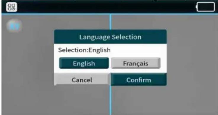
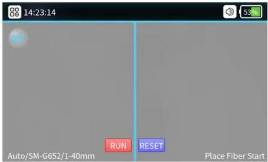
4. Initial Interface
- Language
Selection(English, French, German, Portuguese, Italian, Spanish)
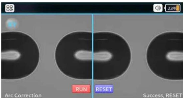
First time ARC Correction(ARC correction could enhance the splicing performance and stability)
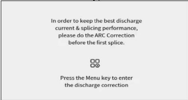
◆ ARC Correction Interface(Cutting and placing the fiber via correct way)
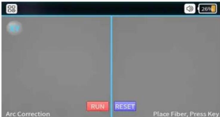
◆ ARC Correction Success(After “success” shows on screen, ARC correction process is done, then using [Rest] button to quit the mode.)
- Description of UI
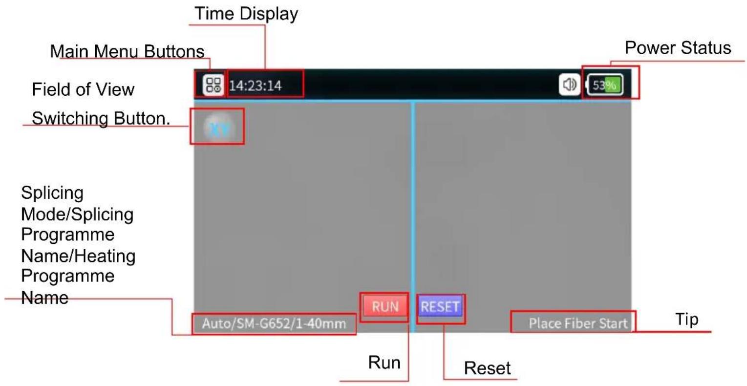
Function of Description
- Function Introduction of the Splicer

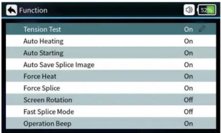
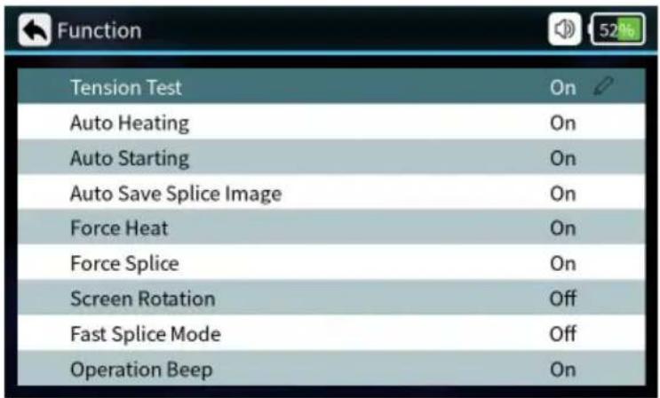
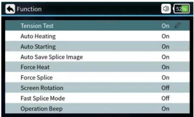
2. Shortcut Function
| Parameters | Instructions |
| Tension Test | When it’s on, the tension test will be executed automatically after splicing. |
| Auto Heating | Put in the optical fiber, cover after automatic heating. |
| Auto Starting | When it’s on, automatically splicing once cover closed. |
| Auto Save Splice Image | When it’s on, automatically saving splice image. |
| Force Heat | When it’s on, no fiber optic detected, pressing the heat button also heats it up. |
| Force splice | When it’s on, the user can press the start button to force the fusion splicing to continue, when the fusion splicing process detects an angle failure or fiber mismatch. |
| Screen Rotation | Screen interface rotated 180° |
| Fast splice Mode | Can be set on or off, fusion time is reduced when fast mode is on. |
| Operation Beep | Beeps can be set to be on or off |
3. Splice Set
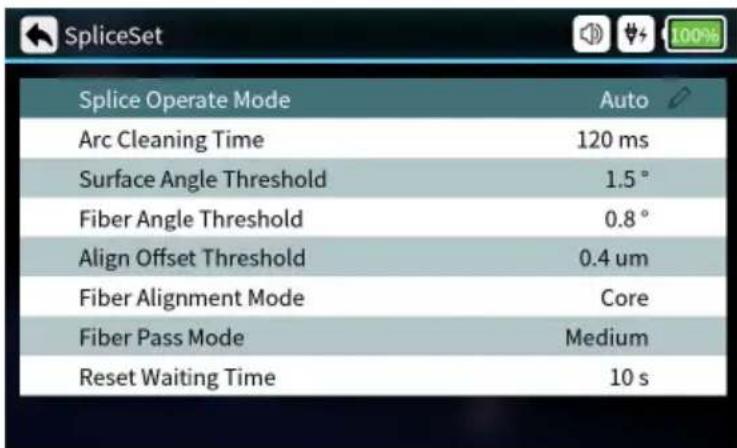
| Parameters Description | |
| Splicer operate Mode | Automatic mode, semiautomatic mode, manual mode optional. |
| Arc Cleaning Time | Clean discharge refers to the cleaning of fine dust adhering to the surface of an optical fiber by discharging the fiber prior to fusion splicing. |
| Surface Angle Threshold | Limit value of fiber end face angle. |
| Fiber Angle Threshold | Angle limit after alignment of left and right fibers. |
| Align offset Threshold | Limit of centre deviation after alignment of left and right fibers. |
| Fiber Alignment Mode | Core alignment, cladding alignment, and fine alignment can be set. |
| Fiber Pass Mode | Low, medium and high standards can be set. |
| Reset Waiting Time | When the tensile test is turned on, waiting time for motor reset after opening the windproof cover. |
4. Edit Splice Program
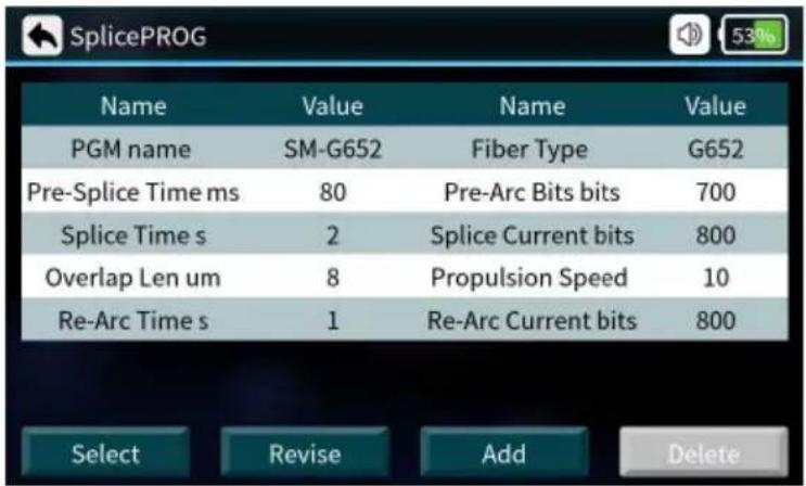
| Edit Splice Program | |
| Splice PN Name of splicer program | |
| Pre-Splice Time | Pre-Splice time can be set from: 0-500 (ms) |
| Splice Time | Splice time can be set from:0-5 (s) |
| Overlap Len | Overlap Len can be set from:0-50 (um) |
| Re-Arc Time | Re-Arc Time can be set from:0-5 (s) |
| Fiber Type Types of Fiber | |
| Pre-Arc Bits | Pre-Arc Bits can be set from:0-4000 (bits) |
| Splice Current Bits | Splice Current can be set from:0-4000 (bits) |
| Propulsion Speed | Propulsion Speed can be set from:0-50 (um/s) |
| Re-Arc Current Bits | Re-Arc Current can be set from:0-4000 (bits) |
5. Sleeve Set
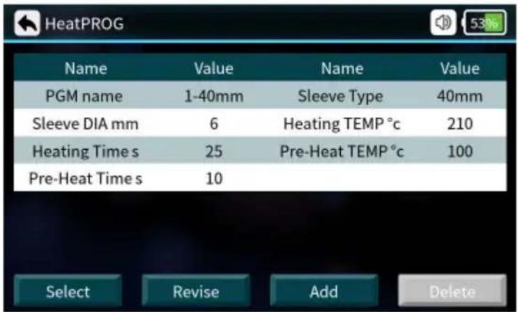
| Parameters | Description |
| Heating PN | There are many heating programs for different shrinkable tubes pre-stored in the system, also many self-set programs are offered to users. |
| Sleeve DIA | 2mm,3mm,4mm,6mm |
| Heating Time | Heat shrink heating time |
| Pre-Heat Time | Pre-heating time |
| Sleeve Type | 10mm-60mm normal tube, FC, SC |
| Heating Temp | The temperature limit of heating process |
| Pre-Heat Temp | The temperature limit of preheating process |
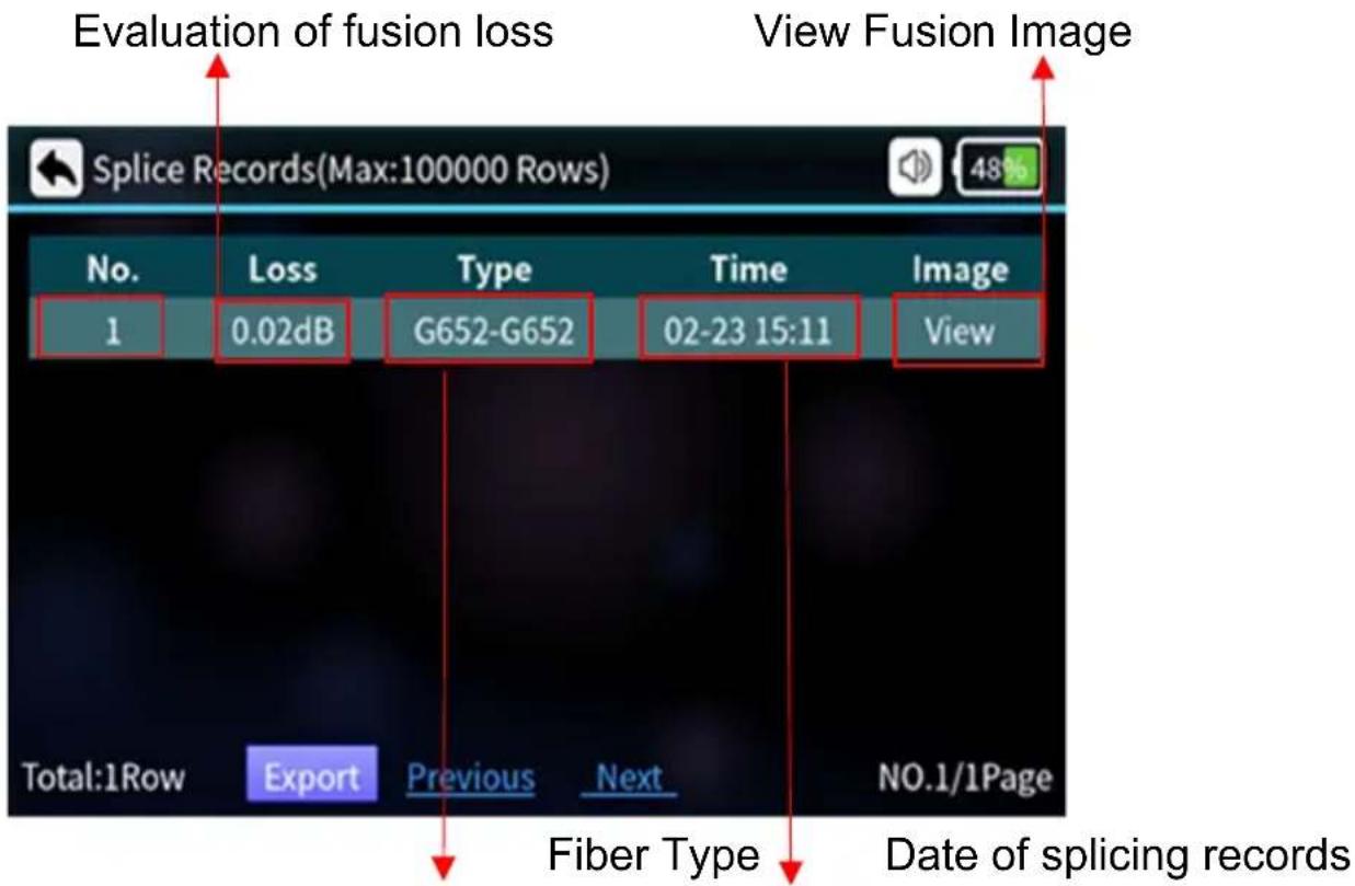
6. Splice Records

| Parameters Description |
| No. Sorting by Splice Time |
| Loss Loss after splicing |
| Type Types of fiber for splicing |
| Time Splice time |
| Image Viewable image of the finished splice |
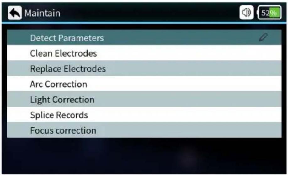
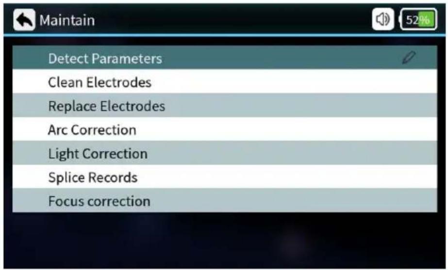
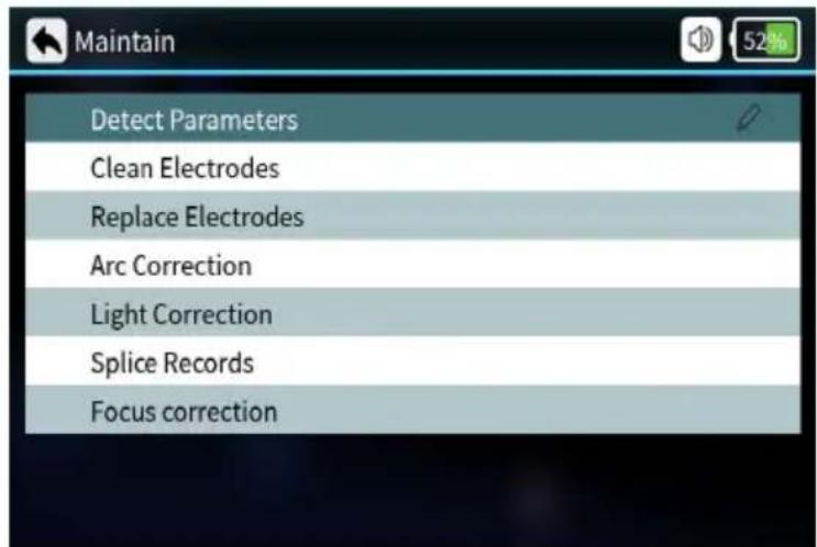
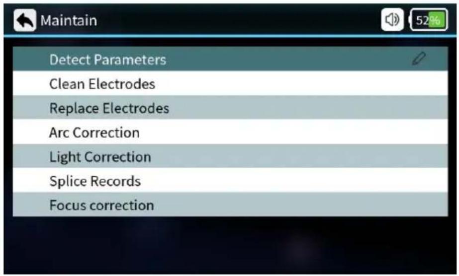
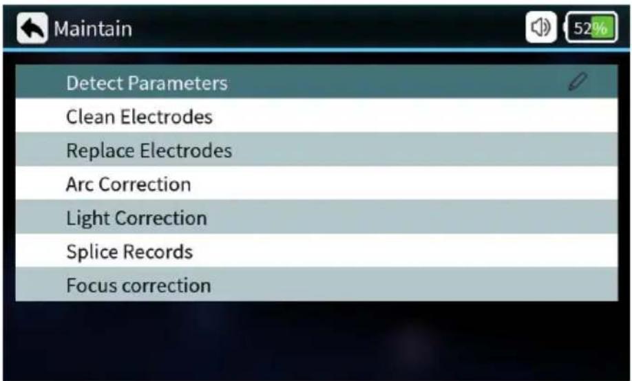
7. Maintain
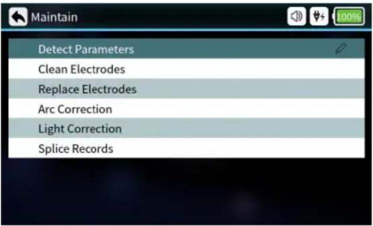
| Parameters Description | |
| Detect Parameters | Automatic self-test of electrode position, motor and other system parameters. |
| Clean Electrodes | Multiple high-current discharges to clean the electrodes. |
| Replace Electrodes | After replacing the electrode, the discharge position is automatically determined and the electrode is stabilized by multiple discharges. |
| Arc Correction | Performs Arc Correction operation and automatically corrects the discharge current. |
| Light Correction | Automatic correction of red light source. |
| Splice Records | Query splice time, evaluate loss, image, etc. |
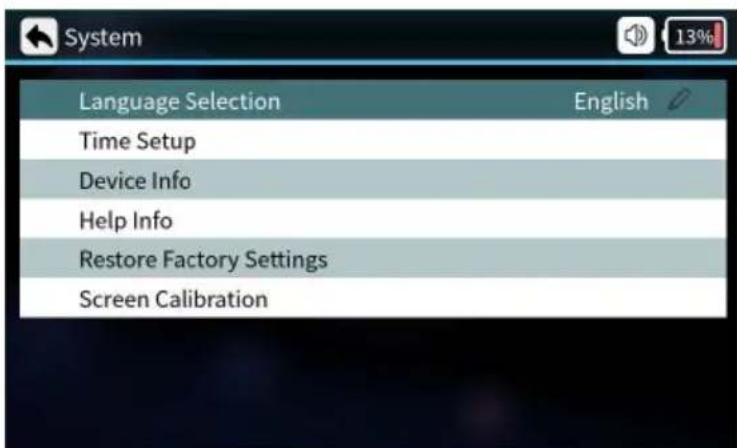
8. System
| Parameters Description | |
| Language Selection | English, French, German, Italian, Portuguese, Spanish |
| Time Setup Setting the time setup | |
| Device Info | Current device related information |
| Help Info instruction manual | |
| Restore Factory Setting | Settings are restored to factory settings |
| Screen Calibration | Calibration touch screen |
Basic operating instructions
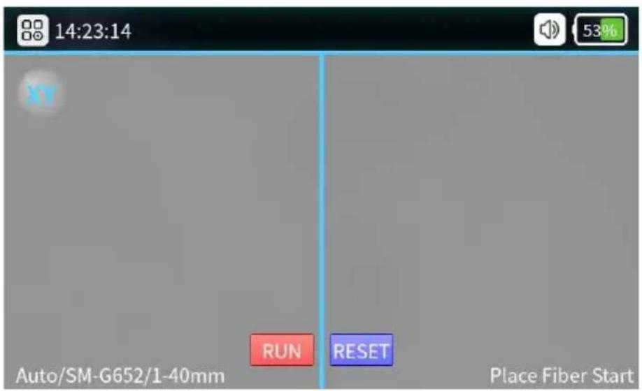
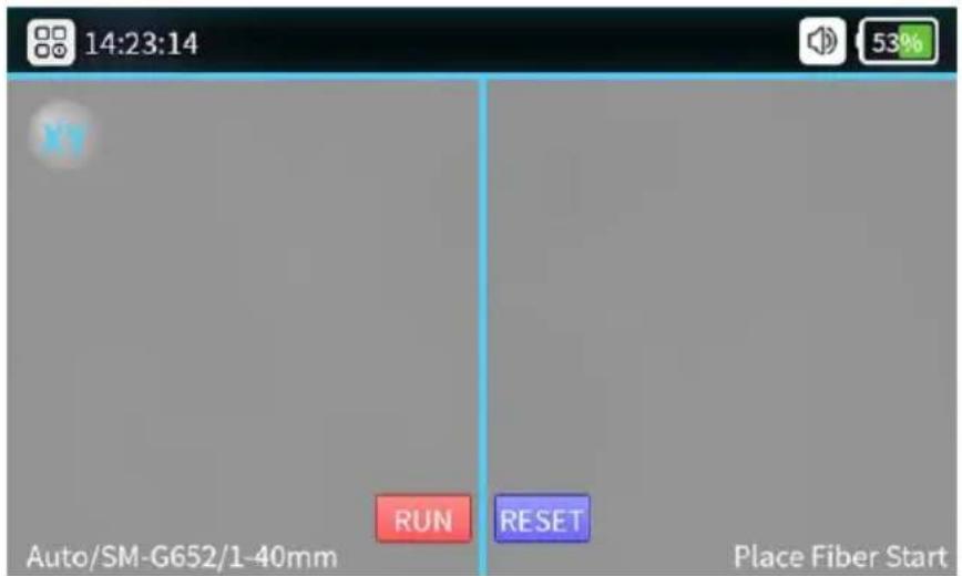
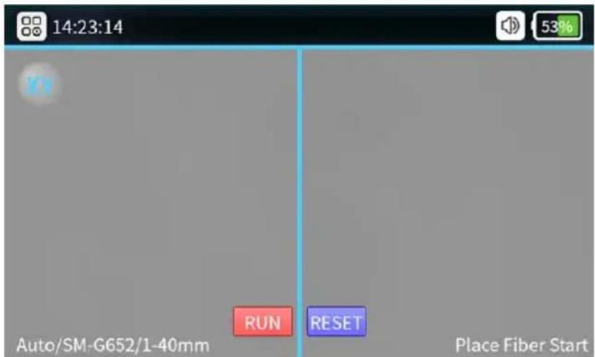
1. Turn on the power
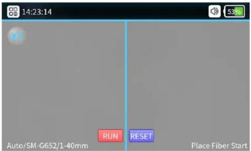
Optical fiber observation interface: Short push the power switch then the indicator on the operation panel will turn to red and the buzzer will be sounds like “Di Di”. All motors will return back to their initial positions and the fiber observation interface shows.
2. Preparation before splicing
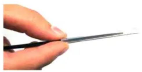
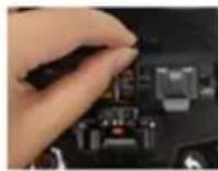
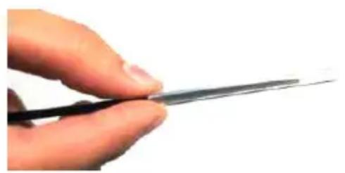
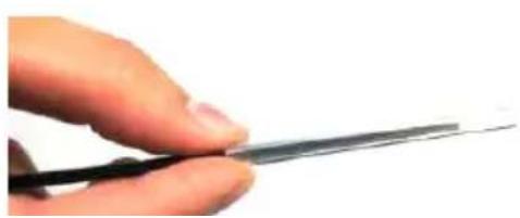
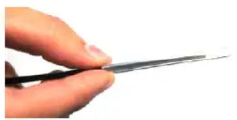
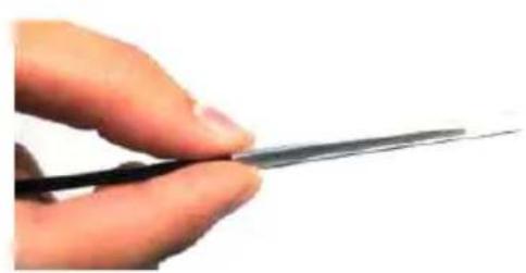
① Put the shrinkable splicing tube on
natural_image
Close-up of a hand holding a thin black pen tip, no text or symbols visiblePut the fiber through the splicing tube so to protect fusion point after splicing. Make sure there is no impurity inside the tube and keep the tube parallel with the fiber.
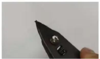
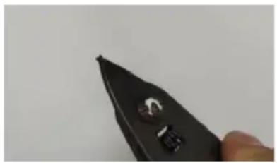
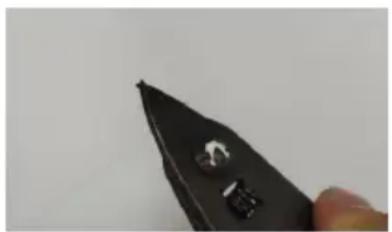
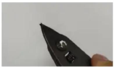
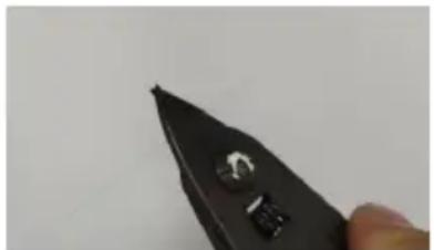
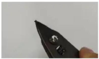
② Strip down the protective layers except the class coating layer.
natural_image
Close-up of a black plastic tool tip with a metallic knob, held by a finger (no text or symbols visible)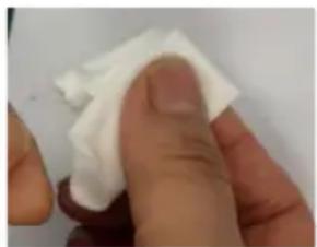
natural_image
Close-up of a finger holding a white cloth or paper, with no visible text or symbols.Strip the coating layer by 40mm with strippers.
After stripping the optical fiber, use dust-free paper dipping with 99% purity alcohol to clean the coating layer in a circular direction. Starting from the interface between the coating and the bare fiber, rotate the paper in the direction of the bare fiber in a circular direction and get rid of the debris of coating layers.
3. Fiber Cutting
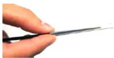
(1) Positioning the tip of the fiber at 13 - 13.5 mm above the top of the slot.
(2) Keep the slider at outer side. Then cover the pressure pad.
(3) Push the slider and finish the cutting.
(4) Open the fiber holder and open up the pressure pad, take the fiber and keep it away from other items in case it may get polluted.
Notice: When there is a poor cutting surface please adjust the blade surface of fiber cleaver. What's more, we'd like to suggest you to use specified fiber cleavers equipped with our machines.
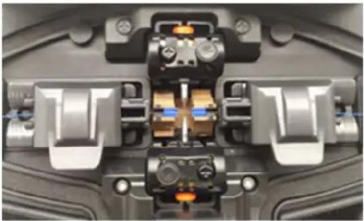
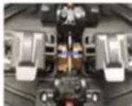
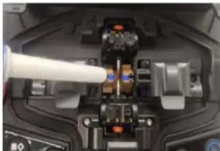
4. Fiber Placement
natural_image
Close-up of a mechanical assembly with internal components and no visible text or symbols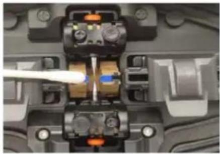
natural_image
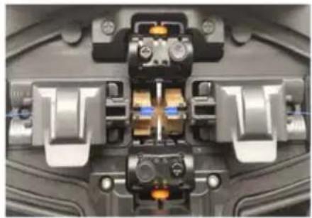
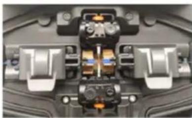
Close-up of a mechanical or electronic component with internal components and a white tool inserted (no visible text or symbols)- Open the wind-proof cover and check if the V-groove is clean. If not please use air blow or blade to clean the V-groove.
- Put the cut fibers in the V-groove of the splicing modules and make sure the fibers are right in the V-groove.
- Check if the end-faces of the fibers are in the position between the electrode tips and the V-grooves. And make sure they're close to the electrodes tips. Or the fibers shall be re-placed.
- Close the wind-proof cover gently and start splicing
5. Check Splicing Result
No. of splicing records
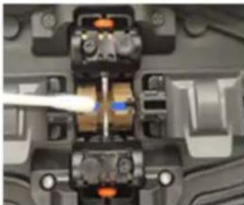
6. Auto-alignment and End Face Correction
To assure splicing quality, the product uses image processing system to observe fibers. But in some conditions the system may not be able to detect the splicing errors. So we still need to inspect the splicing process with eyes through display screen to get better splicing quality.
Close the wind-proof or press the start button, the optical fiber enters the automatic alignment state, and the left and right optical fibers begin to do phase movement. The system will check the cut faces after cleaning discharge, if the end faces are not qualified the splicing will not be started and there will be error notice on the screen. If the cut faces are qualified the aligning process will continue. After alignment the end-face angles of fibers on both sides will be showed on the screen. If the detected angles exceed the limited angle there will be error notice on the screen. The fibers will need to be re-cut.
If it shows following images or notice info in aligning process the system will reset the motors. Users can also push reset button to reset motors and retry to cut or put fibers.
7. Solutions of Abnormal Alignment Issues
| Displayed Images ( X/Y Axis) | Notice Possible Reasons Solutions | ||
 | Fiber on the right side is improperly placed | Fiber on the right side is not placed into the V-groove or it's too short | Reposition the fiber, Re-cut the fiber |
 | Fiber on the left side is improperly placed | Fiber on the left side is not placed into the V-groove or it's too short | Reposition the fiber, Re-cut the fiber |
 | Alignment Error | Fiber on the right/left side is not placed in the V-groove | Reposition the fiber, Re-cut the fiber |
 | Please reposition the fiber | Left/right side cuts too short | Reposition the fiber, re-cut the fiber |
 | Please reposition the fiber | Fibers on left/right side are too long | Reposition the fiber, re-cut the fiber |
 | Fibers are not qualified | Dust or dirt on fibers | Clean and reposition the fibers |
| Displayed Images ( X/Y Axis) | Notice Possible Reasons Solutions | ||
 | Angles of fiber end-faces are not qualified | Problems with the fiber cutting process | Re-cut the fiber |
 | |||
 | |||
 | |||
After fiber alignment the system will automatically discharge and splice. If the setting is set to semiautomatic splice, the message “Alignment complete” is displayed on the screen. Then the user can push start button to splice or push reset button to reset motors.
Maintenance
1. ARC Correction
When the outer environment suddenly change or for following situations the ARC correction will be needed to adjust current intensity so to ensure low loss, high stability splicing.
● Temperature, humidity or air pressure changes
● Aging or pollution of electrodes
● Continuous splice fails or high splicing loss
● Machine is idle for a long time
- Electrodes over used
- Electrodes are newly cleaned or replaced Discharge Correcting Method:
① Choose “Arc Correction” Under
② Put cut fibers on fiber holders and close the wind-proof cover.
natural_image
Close-up of a mechanical assembly with interlocking gears and springs (no visible text or symbols)③ If there is “Large Current” or “Small current” please repeat the operation of ②③ until it shows the correction is successful.
Notice:
The cutting angles under discharge correcting mode are separately set, it's not relative with that under splicing modes.
Discharge correction usually need to be repeated for a couple of times.
Please operate with patience.
2. Detect System Parameters
The self-test function offered is able to test and inspect the system based on several important parameters.
We insist to suggest users to do parameters self-test in case splicing. quality may be affected:
■ After system updating
■ After replacing/move electrodes
■ After enduring long-distance transportation or strong shock
■ After continuous splicing failures or splicing loss is abnormally high
■ When there is continuous over-adjusting in alignment process
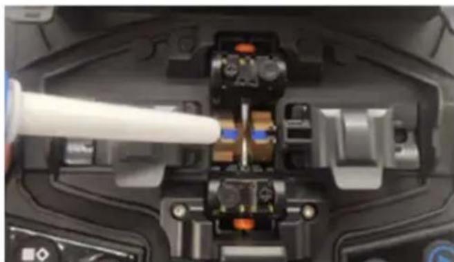
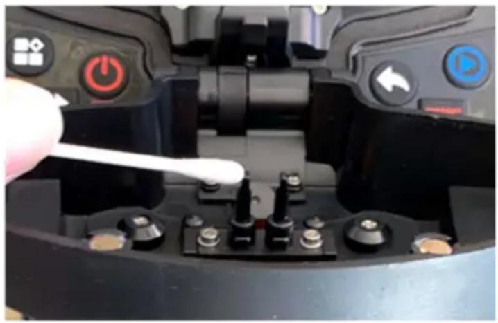
Operations are as following:
①Clean V-groove and pressers with cotton swab dipped with alcohol.
natural_image
Close-up of mechanical components with no visible text or symbols
natural_image
Close-up of a mechanical device with a white tool inserted, showing no visible text or symbols.②Choose “Detect Parameters” under “Maintain”
③Put fibers and close the cover the self-test will be on. Normally the test will continue for 2 minutes. Please observe the notice on the LCD screen, if the test fails please operate according to instructions on screen and Re-enable system detection(Step ①).
natural_image
Close-up of a mechanical or electronic component with internal components and mounting holes (no visible text or symbols)Notice:
Cleaning is the most important step. Please do clean specified parts before further operations.
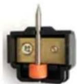
3. Electrodes Replacement
The electrodes will be damaged due to long time use. Please replace the electrodes after 5000-time discharges or the splicing quality will be affected and higher loss as well as lower steadiness of spliced fibers will be caused. The system will automatically remind you that the electrodes need to be replaced when the discharging count reaches 5000. After electrodes replacement the discharging record shall be reset. Be careful of sharp tips of electrodes when replacing them. The operations are as following:
Users shall cut the power and turn off the machine before replacing electrodes, press the power button to switch off the power, the red LED goes out.
Unscrew the screws on electrode cover, take off electrode cover, take off the electrodes.
Put new electrodes into the electrode groove then put the cover back and tight the screws gently.
Check if the two electrodes are at the same horizontal line and the same vertical line. If not please re-put the electrodes.
Turn on the machine and put well cut fiber into the machine, choose "Replace Electrodes" under "Maintain".
Please "Detect system parameters" and do "Arc Correction"
4. V-groove Cleaning
If there is contaminant in V-groove the fibers will deviate from normal position and thus the alignment will be affected so that the splicing loss may be abnormally higher. So users must check and clean V-groove regularly. The operations are as below:
√ Open the wind-proof cover.
√ Clean the contaminant on V-groove with equipped dust blower.
√ Clean the bottom of the V-groove with cotton swab dipped with alcohol.
Notice: Do not touch the tips of electrodes. Clean the V-groove gently and do not use any hard stuff (Blade etc.) to clean the groove in case any damages affecting normal functions caused.
natural_image
Close-up of a mechanical device interior with a white tool inserted, showing internal components and no visible text or symbols.5. Microscope lens Cleaning
The splicer is loaded with image processing system to observe fibers, if the microscope lens are polluted the normal observation will be affected, thus may result in bad splicing result. Users shall clean the 2 lens regularly to ensure they are clean.
A. Turn off the machine and open the wind-proof cover.
B. Clean the lens gently with cotton swab dipped with alcohol.
C. Notice: Do not touch the electrodes. Do not touch the lens with hard stuff.
D. Clean the residual alcohol with clean, dry cotton swab and make sure it's clean and there is no contaminant left.
E. Turn on the machine, observe the image on screen and check if there is dust, if so, please clean the lens again.
natural_image
Close-up of a mechanical component with a white tool inserted, showing internal parts and no visible text or symbols.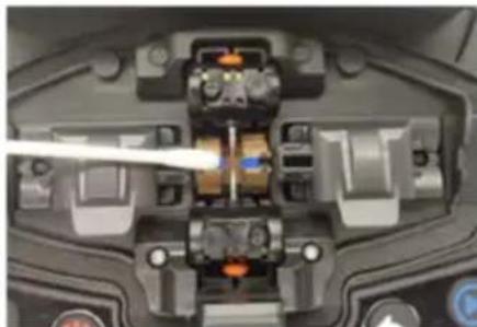
natural_image
Close-up of a mechanical component with internal components and a tool inserted (no visible text or symbols)6. Fiber Pressers Cleaning
Dust on fiber pressers may cause fiber fixing or fiber holding issues and it
will directly affect splicing quality. Users shall check and clean the fiber pressers regularly.
1) Open the wind-proof cover.
2) Clean the surface of the pressers with a fine cotton swab dipped with alcohol, dry the presser with a dry cotton swab after cleaning.
natural_image
Close-up of a robotic control panel with power button, switch, and sensor components (no visible text or symbols)Others
Troubleshooting
| Abnormal Phenomenons | Reasons Solutions | |
| Abnormal sounds such as snorting when discharging | Improper installation position of electrodes | Please strictly following the instruction when installing electrodes |
| Delayed discharge or no discharge | 1. Improper installation position of electrodes2. The tips of electrodes are wrapped by silicon oxide | 1. Please strictly following the instruction when installing electrodes2. Clean the tips of electrodes or replace the electrodes |
| The machine crash when | Improper installation position of electrodes | Please strictly following the instruction when installing |
| discharging electrodes | ||
| Discharge Correction Failure | Current environment is interfering the discharging process | If it keeps warning over-current, please lower the current before discharge correction. Otherwise please increase the current. If it still fails please contact after-sales department. |
| Fibers alignment failures | 1.There is dust on lens, LED light, V-groove.2.Power system malfunction. | Try to clean lens, LED lights and V-groove. If the problem still exists please contact after-sales department. |
| Low quality of splicing point | 1.Dust on fibers2.Wrong fiber type settings or wrong splicing program3.Splicing environment changes4.Controlling motor malfunction | 1.Re-prepare the fibers and splice again.2.Choose right fiber type and right splicing program3.Do discharge correction to adjust current to normal intensity4.Retry parameters self-test |
After-Sales Service card
Description of the problem:
Note
We are constantly improving and design and specifications are subject to change without notice.
All information in this manual has been carefully proofread for accuracy and we reserve the right to explain any typographical errors or omissions.
Legal Notices
◆ Without literal authorization from our company, any organizations or individuals shall not extract, copy part or all of the contents of the manual and shall not be disseminated in any form.
This manual describes the product and the features or functions of its accessories are determined by production batches. Thus the product or its accessories described in the manual may not be the same with the ones you purchased. The manufacturer keeps the right of amending the manual whenever it's necessary without formal notice and shall take no responsibility for such actions.
◆ Notice: Please thoroughly read the instruction manual to operate the splicer more accurately and professionally.
Manufacturer: Shanghaimuxinmuyeyouxiangongsi
Address: Shuangchenglu 803nong11hao1602A-1609shi, baoshanqu, shanghai 200000 CN.
Imported to AUS: SIHAO PTY LTD. 1 ROKEVA STREETEASTWOOD NSW 2122 Australia
Imported to USA: Sanven Technology Ltd. Suite 250, 9166 Anaheim Place, Rancho Cucamonga, CA 91730
| EC | REP |
E-CrossStu GmbH
Mainzer Landstr.69, 60329 Frankfurt am Main.
| UK | REP |
YH CONSULTING LIMITED.
C/O YH Consulting Limited Office 147, Centurion
House, London Road, Staines-upon-Thames, Surrey, TW18 4AX
VEVOR®
TOUGH TOOLS, HALF PRICE
Technical Support and E-Warranty Certificate
www.vevor.com/support
VEVOR®
TOUGH TOOLS, HALF PRICE
natural_image
Close-up of a black optical fiber optic switch with control buttons and metallic tags (no visible text or symbols)POTRZEBUJESZ POMOCY? SKONTAKTUJ SIE Z NAMI!
| Appearance | Name | Function |
 | Menu / Confirm | Enter menu page/Confirm or save |
 | Power On / Off | Turn on/off the power |
 | Next | Switch to next option/Switch X/Y views |
 | Return / Reset | Return/Reset the motor |
 | Start / + | Run to start splicing/Adjust parameters(Increase/Switch) 7 |
 | Heating | Start heating |
2. Opis struktury produktu
2. Funkcja skrótu
Basic operating instructions
1. Włącz zasilanie
① Put the shrinkable splicing tube on
natural_image
Close-up of a hand holding a thin black tool, no visible text or symbolsPut the fiber through the splicing to so to protect fusion point after split. Make sure there is no impurity inside the tube and keep the tube parallel the fiber.
② Strip down the protective layers except the class coatir

natural_image
Close-up of a hand holding a black pen tip with metallic screw (no visible text or symbols)
natural_image
Close-up of a hand holding a white cloth or paper, with no visible text or symbols.Strip the coating layer by 40mm with strippers.
natural_image
Close-up of a mechanical assembly with metallic components and no visible text or symbols
natural_image
Close-up of a mechanical component with internal components and a white cable inserted (no visible text or symbols)natural_image
Abstract geometric pattern with alternating black and white rectangular shapes (no text or symbols)
natural_image
Simple black-and-white horizontal bar pattern with no text or symbols
natural_image
Simple black-and-white graphic of a horizontal bar with two circular ends (no text or symbols)natural_image
Close-up of a mechanical assembly with interlocking gears and housing (no visible text or symbols)natural_image
Close-up of a mechanical component with internal components and a white tool tip (no visible text or symbols)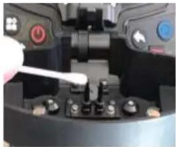
natural_image
Close-up of a mechanical device with a white tool inserted, showing no visible text or symbols.natural_image
Close-up of a mechanical or electronic component with internal components and mounting holes (no visible text or symbols)Ogłoszenie:
natural_image
Close-up of a computer mouse with a white pen inserted, showing internal components (no visible text or symbols)natural_image
Close-up of a computer mouse with a white pen inserted, showing internal components (no visible text or symbols)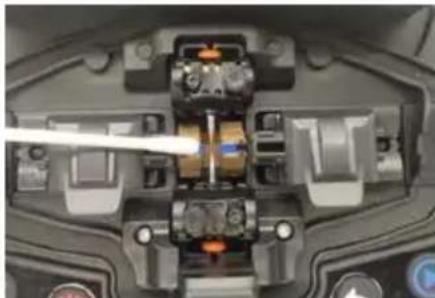
natural_image
Close-up of a mechanical component with internal gears and a tool (no visible text or symbols)natural_image
Close-up of a robotic control panel with power switches and a white plastic tool inserted (no visible text or symbols)Others
STREETEASTWOOD NSW 2122 Australia
Importowane do USA: Sanven Technology Ltd. Suite 250, 9166 Anar
Place, Rancho Cucamonga, CA 91730
| EC | REP |
E-CrossStu GmbH
Mainzer Landstr.69, 60329 Frankfurt am Main
| UK | REP |
YH CONSULTING LIMITED.
C/O YH Consulting Limited Office 147, Centurion
House, London Road, Staines-upon-Thames, Surrey
TW18 4AX
VEVOR®
TOUGH TOOLS, HALF PRICE
www.vevor.com/support
VEVOR®
TOUGH TOOLS, HALF PRICE
natural_image
Close-up of a black optical fiber optic switch with control buttons and mounting bracket (no visible text or symbols)| Appearance | Name | Function |
 | Menu / Confirm | Enter menu page/Confirm or save |
 | Power On / Off | Turn on/off the power |
 | Next | Switch to next option/Switch X/Y views |
 | Return / Reset | 7 Return/Reset the motor |

flowchart
graph LR
    A["Start"] --> B["Run"]
    B --> C["Reset"]
    C --> D["Tip"]
Function of Description
Basic operating instructions
① Put the shrinkable splicing tube on

natural_image
Close-up of a hand holding a thin black tool, no visible text or symbolsPut the fiber through the splicing to so to protect fusion point after splicing. Make sure there is no impurity inside the tube and keep the tube parallel the fiber.
② Strip down the protective layers except the class coatir

natural_image
Close-up of a hand holding a black pen tip with metallic rivets (no visible text or symbols)
natural_image
Close-up of a finger holding a white cloth or paper, with no visible text or symbols.Strip the coating layer by 40mm with strippers.
natural_image
Close-up of a mechanical assembly with metallic components and orange ports (no visible text or symbols)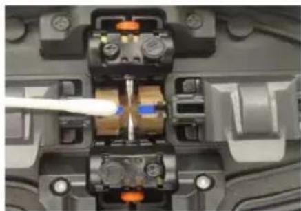
natural_image
Close-up of a mechanical component with internal components and a white tool inserted (no visible text or symbols)natural_image
Close-up of a mechanical assembly with interlocking gears and housing (no visible text or symbols)natural_image
Close-up of electronic components with a white filament interacting with a central component (no visible text or symbols)
natural_image
Close-up of a mechanical device with a white tool inserted, showing no visible text or symbols.natural_image
Close-up of a mechanical or electronic component with internal components and mounting holes (no visible text or symbols)Beachten:
natural_image
Close-up of a mechanical component with a white tool inserted, showing internal parts and no visible text or symbols.natural_image
Close-up of a mechanical component with a white tool inserted, showing internal parts and no visible text or symbols.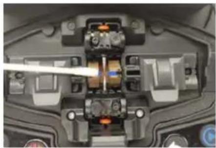
natural_image
Close-up of a mechanical component with internal components and a tool inserted (no visible text or symbols)natural_image
Close-up of a mechanical component with multiple switches and a white tool inserted, no visible text or symbols.Others
Fehlerbehebung
C/O YH Consulting Limited Office 147, Centurion House, London Road, Staines-upon-Thames, Surrey
VEVOR®
TOUGH TOOLS, HALF PRICE
www.vevor.com/support
VEVOR®
TOUGH TOOLS, HALF PRICE
natural_image
Close-up of a black optical fiber optic switch with control buttons and metallic tags (no visible text or symbols)BESOIN D'AIDE? CONTACTEZ-NOUS!
| Appearance | Name | Function |
 | Menu / Confirm | Enter menu page/Confirm or save |
 | Power On / Off | Turn on/off the power |
 | Next | Switch to next option/Switch X/Y views |
 | Return / Reset | Return/Reset the motor |
 | Start / + | 7Run to start splicing/Adjust parameters(Increase/Switch) |
Function of Description
Basic operating instructions
1. Allumer l'alimentation
① Put the shrinkable splicing tube on
natural_image
Close-up of a hand holding a thin, metallic tool against a white background (no text or symbols visible)Put the fiber through the splicing to so to protect fusion point after split 19 Make sure there is no impurity inside the tube and keep the tube parallel
② Strip down the protective layers except the class coatir
natural_image
Close-up of a hand holding a black pen tip with a small circular mark and the number '15' on it (no text or symbols visible)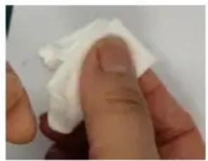
natural_image
Close-up of a hand holding a white cloth or paper over a surface (no text or symbols visible)Strip the coating layer by 40mm with strippers.
natural_image
Close-up of a mechanical assembly with metallic components and no visible text or symbols
natural_image
Close-up of a mechanical or electronic component with internal components and a white tool inserted (no visible text or symbols)natural_image
Close-up of a mechanical assembly with interlocking gears and housing (no visible text or symbols)natural_image
Close-up of electronic components with a white filament inserted, no visible text or symbols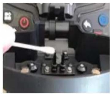
natural_image
Close-up of a mechanical component with a white tool inserted, showing no visible text or symbols.natural_image
Close-up of a mechanical or electronic component with internal components and mounting holes (no visible text or symbols)Avis:
natural_image
Close-up of a mechanical component with a white tool inserted, showing internal components and no visible text or symbols.natural_image
Close-up of a mechanical device with a white tool inserted, showing internal components and no visible text or symbols.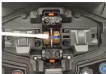
natural_image
Close-up of a mechanical component with internal parts and a white tool inserted (no visible text or symbols)natural_image
Close-up of a robotic control panel with a white tool inserted, showing no visible text or symbols.Others
Dépannage
Anaheim Place, Rancho Cucamonga, CA 91730
| EC | REP |
E-CrossStu GmbH
Mainzer Landstr.69, 60329 Frankfurt am Main
| UK | REP |
YH CONSULTING LIMITED.
C/O YH Consulting Limited Office 147, Centurion House, London Road, Staines-upon-Thames, Surrey TW18 4AX
VEVOR®
TOUGH TOOLS, HALF PRICE
natural_image
Close-up of a black optical fiber optic switch with control buttons and a display panel (no visible text or symbols)HULP NODIG? NEEM CONTACT MET ONS OP!
| Appearance | Name | Function |
 | Menu / Confirm | Enter menu page/Confirm or save |
| [KABK] | Power On / Off | Turn on/off the power |
 | Next | Switch to next option/Switch X/Y views |
 | Return / Reset | Return/Reset the motor |
 | Start / + | Run to start splicing/Adjust parameters(Increase/Switch) |
 | Heating | Start heating |
Bewerk Splice-programma
Basic operating instructions
① Put the shrinkable splicing tube on
natural_image
Close-up of a hand holding a thin black tool, no visible text or symbolsPut the fiber through the splicing to so to protect fusion point after split. Make sure there is no impurity inside the tube and keep the tube parallel the fiber.
② Strip down the protective layers except the class coatir
natural_image
Close-up of a hand holding a black pen tip with metallic rivets (no visible text or symbols)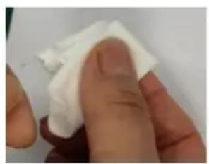
natural_image
Close-up of a hand holding a white cloth or paper over a surface (no text or symbols visible)Strip the coating layer by 40mm with strippers.
natural_image
Close-up of a mechanical assembly with metallic components and no visible text or symbols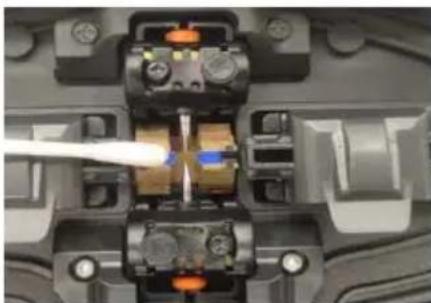
natural_image
Close-up of a mechanical component with a white tool tip inserted, showing internal components and mounting holes (no visible text or symbols)natural_image
Close-up of a mechanical assembly with internal components and mounting holes (no visible text or symbols)③ Als er sprake is van “Grote stroom” of “Kleine stroom”, herhaal dan
natural_image
Close-up of a mechanical component with orange and black components, no visible text or symbols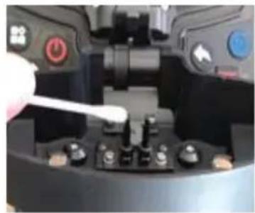
natural_image
Close-up of a mechanical device with a hand holding a white tool near a central component (no visible text or symbols)② Kies "Parameters detecteren" onder "Onderhouden"
natural_image
Close-up of a mechanical component with internal components and mounting holes (no visible text or symbols)Kennisgeving:
natural_image
Close-up of a mechanical component with a white tool inserted, showing internal parts and no visible text or symbols.natural_image
Close-up of a mechanical component with a white tool inserted, showing internal parts and no visible text or symbols.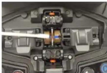
natural_image
Close-up of a mechanical component with internal components and a tool inserted (no visible text or symbols)natural_image
Close-up of a robotic arm with sensors and control buttons, no visible text or symbolsOthers
Probleemoplossing
C/O YH Consulting Limited Office 147, Centurion House, London Road, Staines-upon-Thames, Surrey TW18 4AX
VEVOR®
TOUGH TOOLS, HALF PRICE
www.vevor.com/support
VEVOR®
TOUGH TOOLS, HALF PRICE
natural_image
Close-up of a black optical fiber optic switch with control buttons and mounting bracket (no visible text or symbols)BEHÖVER HJÄLP? KONTAKTA OSS!
| Appearance | Name | Function |
 | Menu / Confirm | Enter menu page/Confirm or save |
 | Power On / Off | Turn on/off the power |
 | Next | Switch to next option/Switch X/Y views |
 | Return / Reset | Return/Reset the motor |
 | Start / + | Run to start splicing/Adjust parameters(Increase/Switch) |
 | Heating | Start heating |
natural_image
Close-up of a black surface with a red rectangular highlight, no visible text or symbolsBatterifixeringsknapp
Function of Description
2. Genvägsfunktion
Basic operating instructions
1. Slå på strömmen
① Put the shrinkable splicing tube on
Put the fiber through the splicing to so to protect fusion point after splicing. Make sure there is no impurity inside the tube and keep the tube parallel the fiber.
② Strip down the protective layers except the class coatir
natural_image
Close-up of a black pen tip with metallic screw and Chinese character '活' (live) on the tip, held by a finger (no other text or symbols visible)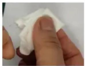
natural_image
Close-up of a hand holding a white cloth or paper over a surface (no text or symbols visible)Strip the coating layer by 40mm with strippers.
natural_image
Close-up of a mechanical assembly with gears and levers (no visible text or symbols)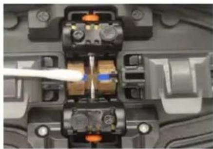
natural_image
Close-up of a mechanical component with internal components and a white tool tip (no visible text or symbols)① Välj "Arc Correction" under
natural_image
Close-up of a mechanical component with internal components and mounting holes (no visible text or symbols)natural_image
Close-up of electronic components with a white filament inserted, no visible text or symbols
natural_image
Close-up of a mechanical component with a white tool inserted, showing no visible text or symbols.natural_image
Close-up of a mechanical or electronic component with internal components and mounting holes (no visible text or symbols)Varsel:
natural_image
Close-up of a mechanical component with a white tool inserted, showing internal components and no visible text or symbols.5. Mikroskoplinsrengöring
natural_image
Close-up of a mechanical component with a white tool inserted, showing internal parts and no visible text or symbols.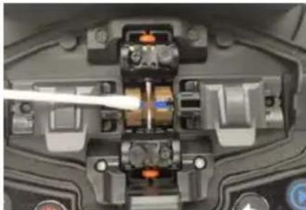
natural_image
Close-up of a mechanical component with internal components and a white tool inserted (no visible text or symbols)natural_image
Close-up of a robotic arm with white plastic tape and control buttons (no readable text or symbols)Others
Felsökning
www.vevor.com/support
VEVOR®
TOUGH TOOLS, HALF PRICE
natural_image
Close-up of a black optical fiber optic switch with control buttons and a display panel (no visible text or symbols)| Appearance | Name | Function |
 | Menu / Confirm | Enter menu page/Confirm or save |
 | Power On / Off | Turn on/off the power |
 | Next | Switch to next option/Switch X/Y views |
 | Return / Reset | Return/Reset the motor |
 | Start / + | Run t7 start splicing/Adjust parameters(Increase/Switch) |
Function of Description
Basic operating instructions
① Put the shrinkable splicing tube on
natural_image
Close-up of a hand holding a thin black tool, no visible text or symbolsPut the fiber through the splicing to so to protect fusion point after split. Make sure there is no impurity inside the tube and keep the tube parallel the fiber.
② Strip down the protective layers except the class coatir
natural_image
Close-up of a black metal tool tip with a small metallic knob, held by a finger (no text or symbols visible)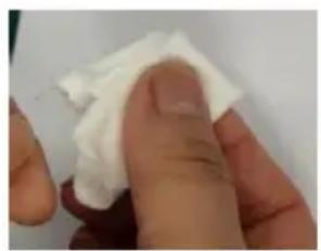
natural_image
Close-up of a finger holding a white cloth or paper, with no visible text or symbols.Strip the coating layer by 40mm with strippers.
natural_image
Close-up of a mechanical assembly with metallic components and no visible text or symbols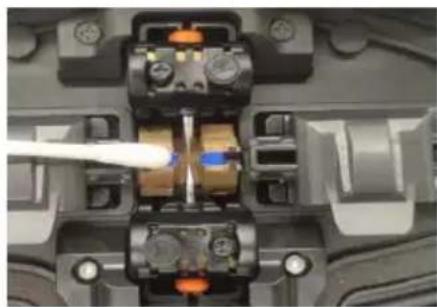
natural_image
Close-up of a mechanical or electronic component with internal components and a white tool inserted (no visible text or symbols)natural_image
Close-up of a mechanical assembly with interlocking gears and housing (no visible text or symbols)natural_image
Close-up of electronic components with a white filament interacting with a central connector (no visible text or symbols)
natural_image
Close-up of a mechanical device with a hand holding a white tool, showing no visible text or symbols.natural_image
Close-up of a mechanical or electronic component with internal components and mounting holes (no visible text or symbols)Aviso:
natural_image
Close-up of a mechanical component with a white tool inserted, showing internal parts and no visible text or symbols.natural_image
Close-up of a mechanical device with a white tool inserted, showing internal components and no visible text or symbols.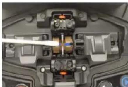
natural_image
Close-up of a mechanical component with internal components and a tool inserted (no visible text or symbols)natural_image
Close-up of a robotic device's control panel with power and switch buttons, no visible text or symbolsOthers
C/O YH Consulting Limited Office 147, Centurion House, London Road, Staines-upon-Thames, Surrey TW18 4AX
VEVOR®
TOUGH TOOLS, HALF PRICE
natural_image
Close-up of a black optical fiber optic switch with control buttons and a display panel (no visible text or symbols)| Appearance | Name | Function |
 | Menu / Confirm | Enter menu page/Confirm or save |
 | Power On / Off | Turn on/off the power |
 | Next | Switch to next option/Switch X/Y views |
 | Return / Reset | Return/Reset the motor |
 | Start / + | Run to start splicing/Adjust parameters(Increase/Switch) |
 | Heating | Start heating |
Basic operating instructions
① Put the shrinkable splicing tube on
natural_image
Close-up of a hand holding a thin black tool, no visible text or symbolsPut the fiber through the splicing to so to protect fusion point after splicing. Make sure there is no impurity inside the tube and keep the tube parallel the fiber.
② Strip down the protective layers except the class coatir
natural_image
Close-up of a hand holding a black pen tip with metallic rivets (no visible text or symbols)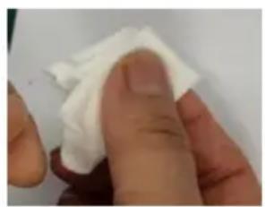
natural_image
Close-up of a finger holding a white cloth or paper, with no visible text or symbols.Strip the coating layer by 40mm with strippers.
natural_image
Close-up of a mechanical assembly with metallic components and internal components (no visible text or symbols)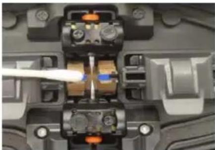
natural_image
Close-up of a mechanical component with internal components and a white tool inserted (no visible text or symbols)natural_image
Close-up of a mechanical assembly with interlocking gears and housing (no visible text or symbols)natural_image
Close-up of electronic components with a white filament interacting with a central connector (no visible text or symbols)
natural_image
Close-up of a mechanical device with a hand holding a white tool, showing no visible text or symbols.natural_image
Close-up of a mechanical component with internal components and mounting holes (no visible text or symbols)Avviso:
natural_image
Close-up of a mechanical component with a white tool inserted, showing internal parts and no visible text or symbols.natural_image
Close-up of a mechanical device with a white tool inserted, showing internal components and no visible text or symbols.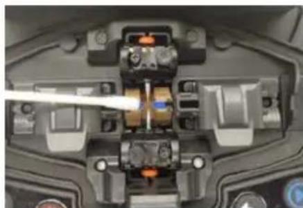
natural_image
Close-up of a mechanical component with internal components and a tool inserted (no visible text or symbols)natural_image
Close-up of a robotic control panel with a white tool inserted, showing no visible text or symbols.Others
Importato in AUS: SIHAO PTY LTD. 1 ROKEVA STREETEASTWOOD NSW 2122 Australia
Importato negli USA: Sanven Technology Ltd. Suite 250, 9166 Anaheim Place, Rancho Cucamonga, CA 91730
| EC | REP |
E-CrossStu GmbH
Mainzer Landstr.69, 60329 Frankfurt am Main
| UK | REP |
YH CONSULTING LIMITED.
C/O YH Consulting Limited Office 147, Centurion House, London Road, Staines-upon-Thames, Surrey TW18 4AX
VEVOR®
TOUGH TOOLS, HALF PRICE