SS103 - Multimeter Vevor - Free user manual and instructions
Find the device manual for free SS103 Vevor in PDF.

| Product Type | True RMS Insulation Tester (Digital Multimeter) |
| Brand | Vevor |
| Model | SS103 |
| Dimensions | 192 x 92 x 61 mm |
| Weight | Approx. 469 g (batteries included) |
| Power Supply | 6 AAA 1.5 V alkaline batteries |
| Display | 3 3/4 digit LCD with analog bar graph |
| Main Functions | AC/DC voltage measurement (1000 V max), resistance, continuity (<30 Ω), insulation resistance (100 V, 250 V, 500 V, 1000 V), data hold, auto/manual ranging, backlight, auto power off |
| Measurement Category | CAT III 1000 V, pollution degree 2 |
| Maximum Admissible Voltage | 1000 V AC/DC |
| Input Impedance (AC Voltage) | > 1 MΩ |
| Input Impedance (DC Voltage) | Approx. 10 MΩ |
| AC Measurement Frequency | 40 Hz to 400 Hz (True RMS) |
| Operating Temperature | 0°C to 40°C, RH < 75% |
| Storage Temperature | -20°C to 60°C, RH < 85% |
| Maximum Altitude | 2000 m |
| Protection Rating | IP40 |
| Maintenance and Cleaning | Wipe with a damp cloth and mild detergent; clean the terminals with an alcohol-soaked cotton swab |
| Batteries | Replace the 6 AAA batteries as soon as the low battery symbol appears |
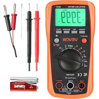
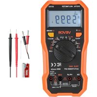
| Included Accessories | 1 pair of test leads, 1 pair of alligator clips, 1 user manual |
| Warranty | 1 year (excluding batteries and damage due to misuse) |
| Certifications | CE, FCC (Part 15, Class B) |
Frequently Asked Questions - SS103 Vevor
User questions about SS103 Vevor
0 question about this device. Answer the ones you know or ask your own.
Ask a new question about this device
Download the instructions for your Multimeter in PDF format for free! Find your manual SS103 - Vevor and take your electronic device back in hand. On this page are published all the documents necessary for the use of your device. SS103 by Vevor.
USER MANUAL SS103 Vevor
Affordable. Reliable. Home Improvement.
True Rms Insulation Tester
Model:SS103
Model:SS103
This is the original instruction, please read all manual instructions care before operating. VEVOR reserves a clear interpretation of our user manual. The appearance of the product shall be subject to the product received. Please forgive us that we won't inform you again if there are technology or software updates on our product.
 | Warning-To reduce the risk of injury, user must read inst manual carefully. |
 | CORRECT DISPOSALThis product is subject to the provision of european Dire 2012/19/EU. The symbol showing a wheelie bin crossed indicates that the product requires separate refuse collecti the European Union. This applies to the product and all accessories marked with this symbol. Products marked as may not be discarded with normal domestic waste, but n taken to acollection point for recycling electrical and elect devices. |
| FCC Information | FCC Information:CAUTION: Changes or modifications not expressly approve the party responsible for compliance could void the user's authority to operate the equipment!This device complies with Part 15 of the FCC Rules. Or subject to the following two conditions:1) This product may cause harmful interference.2)This product must accept any interference received, incl interference that may cause undesired operation.WARNING: Changes or modifications to this product not expressly approved by the party.responsible for compliance could void the user's authority to operate the product.Note: This product has been tested and found to comply limits for a Class B digital device pursuant to Part 15 o Rules, These limits are designed to provide reasonable protection against harmful interference in a residential installation.This product generates, uses and can radiate radio frequ energy, and if not installed and used in accordance with instructions, may cause harmful interference to radiocommunications. However, there is no guarantee that interference will not occur in a particular installation. If the product does cause harmful interference to radio or televi reception,which can be determined by turning the product and on, the user is encouraged to try to correct the int by one or more of the following measures.Reorient or relocate the receiving antenna.Increase the distance between the product and receiverConnect the product to an outlet on a circuit different to which the receiver is connected.Consult the dealer or an experienced radio/TV technicia assistance. |
WARRANTY
This instrument is warranted to be free from defects in material and workman for a period of one year. Any instrument found defective within one year from delivery date and returned to the factory with transportation charges prepaid, be repaired, adjusted, or replaced at no charge to the original purchaser. This warranty does not cover expandable items such as batteries. If the defect has been caused by a misuse or abnormal operating condition, the repair will be at a nominal cost.
INTRODUCTION
The Product is a battery-powered, true-RMS Insulation Tester designed to measure DC and AC voltage, resistance, continuity, and insulation resistance. Insulation resistance tests, you can select a desired test voltage among 100V 250V, 500V and 1000V.
The Meter features Data Hold, auto/manual ranging, automatic poweroff, backlig-polarity indication, over range indication, etc. It is accurate, multifunctional, reliance and easy to operate.
SAFETY INFORMATION
The Meter complies with Measurement Category III (CAT III 1000V) and Pollu Degree 2.
WARNING
To avoid possible electric shock or personal injury, follow these guidelines:
- Do not use the Meter if it is damaged. Before you use the Meter, inspect Pay particular attention to the insulation surrounding the connectors.
- Inspect the test leads for damaged insulation or exposed metal. Check the leads for continuity. Replace damaged test leads before you use the Meter.
- Do not use the Meter if it operates abnormally. Protection may be impaired. When in doubt, have the Meter serviced.
- Do not operate the Meter where explosive gas, vapor or dust is present.
- Do not apply more than the rated voltage, as marked on the Meter, between terminals or between any terminal and earth ground.
- Before use, verify the Meter's operation by measuring a known voltage.
- When servicing the Meter, use only specified replacement parts.
- Use caution when working with voltages above 30V ac rms, 42V ac peak, dc. Such voltages pose a shock hazard.
- When using the probes, keep your fingers behind the finger guards on the probes.
- When making connections, connect the common test lead before you connect the live test lead. When you disconnect test leads, disconnect the live test lead first.
- Remove all the test leads from the Meter before you open the battery cover case.
- Do not operate the Meter with the battery cover or portions of the case r or loosened.
- To avoid false readings which could lead to possible electric shock or pers injury, replace the batteries as soon as the low battery indicator appears.
- To avoid electric shock, do not touch any naked conductor with hand or s do not ground yourself while using the Meter.
- When Data Hold is activated (is displayed), caution must be used as hazardous voltages may be present.
- Do not use the Meter in a manner not specified by this manual, or the s features provided by the Meter may be impaired.
- Adhere to local and national safety codes. Individual protective equipment m be used to prevent shock and arc blast injury where hazardous live conductc exposed.
- When a terminal of the Meter is connected to a dangerous live potential, be noted that this potential can occur at all other terminals!
- CAT III - Measurement Category III is for measurements performed in the installation. Examples are measurements on distribution boards, circuit breakers, wiring, including cables, bus-bars, junction boxes, switches, socket-outlets in the fixed installation, and equipment for industrial use and some other equipment, example, stationary motors with permanent connection to the fixed installation.
Do not use the Meter for measurements within Measurement
Category IV.
Caution
To avoid possible damage to the Meter or to the equipment under test, follo guidelines:
- Disconnect circuit power and discharge all capacitors thoroughly before testir resistance, continuity, and insulation resistance.
- Use the proper terminals, function and range for your measurements.
- Before turning the rotary switch to change function, disconnect the test lead from the circuit under test.
Symbols
 | Both Alternating and Direct current |
 | Caution, risk of danger, refer to the operating manual before |
 | Caution, risk of electric shock. |
 | Earth (ground) Terminal |
 | Conforms to European Union directives |
 | The equipment is protected throughout by double insulation or reinforced insulation. |
Product Description and Specifications

Read all safety warnings and all instructions. Failure to follow the warn and instructions may result in electric shock, fire and/or serious injury.
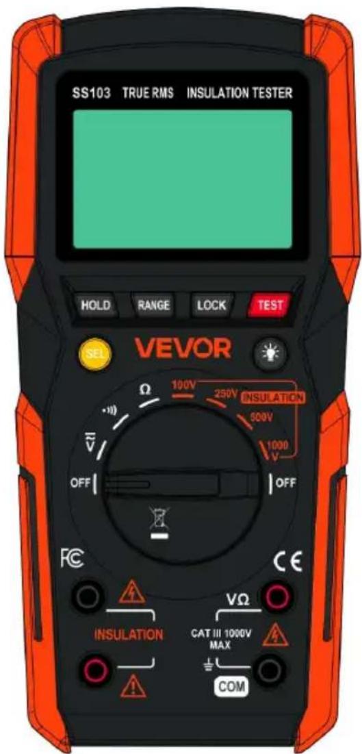
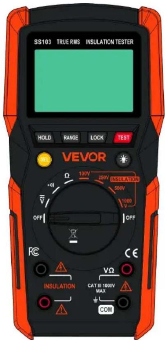
FRONT PANEL
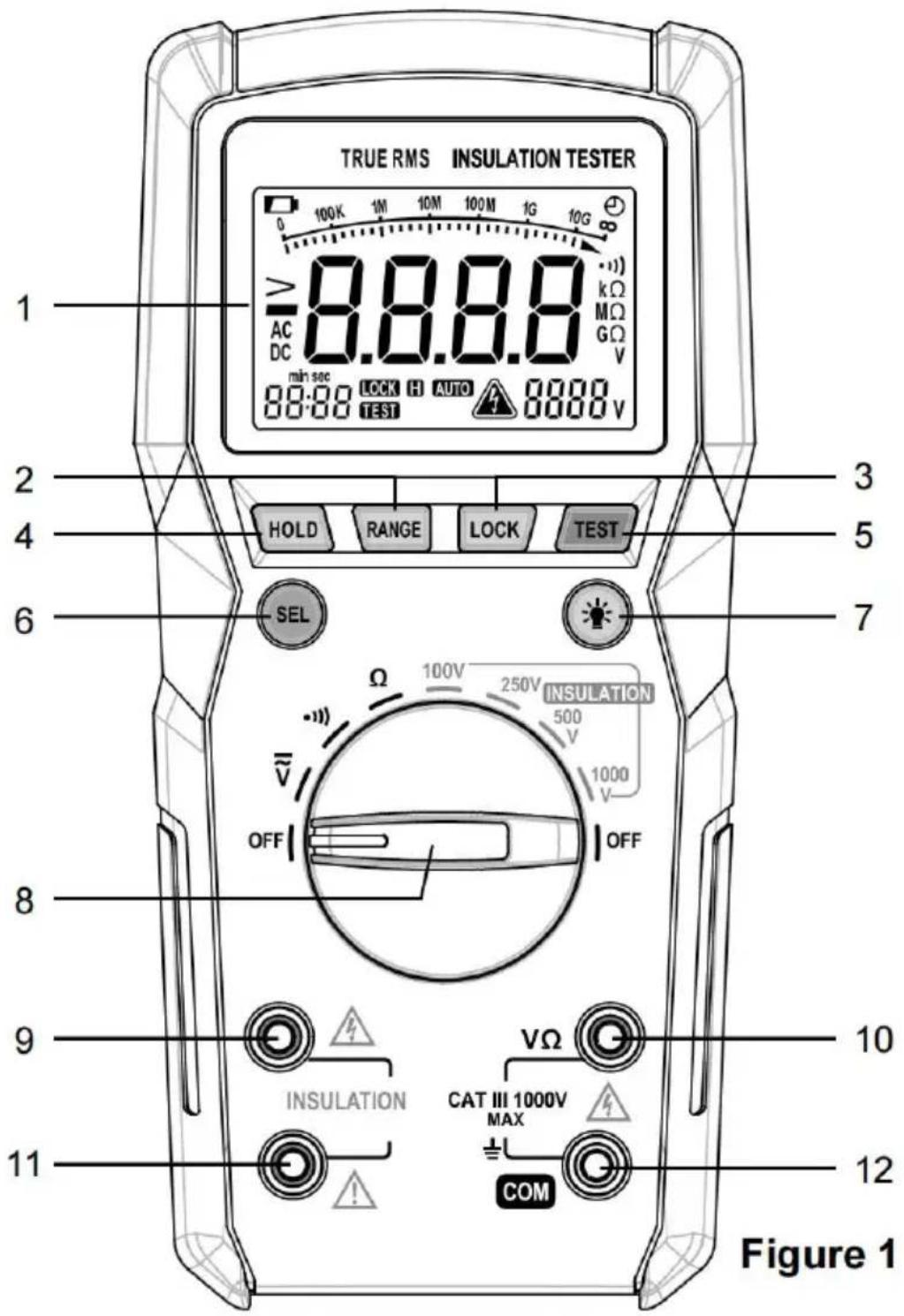
- LCD Display
- " RANGE " Button
Used to switch between autoranging and manual ranging as well as to select a desired manual range.
3. " LOCK " Button
Used to lock the insulation test or release the lock.
In insulation test mode, press the LOCK button once to apply a test lock. Press the TEST button once to start the insulation test. The test lock acts to hold down this TEST button until LOCK or TEST is pressed again.
4. " HOLD " Button
Used to enable/disable Data Hold.
5. "TEST" Button
Used to start/stop insulation tests.
6. " SEL " Button
Used to switch between DC and AC voltage functions.
7. "="Button
Used to turn on/off the backlight.
8. Rotary Switch
Used to select a desired function as well as to turn on/off the Meter.
To save battery charge, set this switch to the OFF position when the Meter is not in use.
9. "INSULATION" negative terminal (-)
Plug-in connector for the black test lead for insulation tests.
10. "VΩ terminal
Plug-in connector for the red test lead for voltage, resistance measurements as well as continuity tests.
11. "INSULATION" positive terminal (+)
Plug-in connector for the red test lead for insulation tests.
12. " COM " terminal
Plug-in connector for the black test lead for voltage, resistance measurements well as continuity tests.
Instruction for the Built-in Buzzer:
The buzzer will sound a beep when the Meter is powered on.
When a button is pressed, the buzzer will sound a beep if this press is eff
The buzzer will sound three beeps before the Meter turns off automatically.
UNDERSTANDING THE DISPLAY
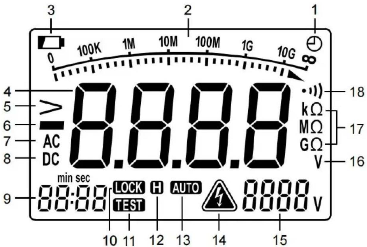
Figure 2
Explanations:
| NO. | Symbol | Description |
| 1 |  | Automatic power-off is enabled. |
| 2 | 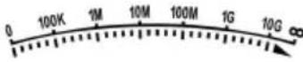 | Analog bargraph with scale for insulation tes |
| 3 |  | Low batteries. Indicates the batteries should replaced immediately. |
| 4 |  | Primary Display |
| 5 |  | Overrange indication for insulation tests. |
| 6 |  | Negative Sign |
| 7 |  | Alternating Current |
| 8 |  | Direct Current |
| 9 |  | Test time display for insulation tests. |
| 10 |  | The insulation testis locked. |
| 11 |  | The insulation testis ongoing. |
| 12 |  | Data Hold is enabled. |
| 13 |  | Autoranging |
| 14 |  | The Meter detects a voltage greater than Be cautious!When performing insulation tests, this icon indicates that the Meter is outputting a high voltage. |
| 15 |  | Insulation Test Voltage Display |
| 16 | ### | Unit for Voltage Measurements |
| 17 |  | Units for Resistance Measurements |
| 18 | ### | Continuity test function is selected. |
GENERAL SPECIFICATION
Display: 3 3/4-digit LCD
Negative Polarity Indication: shown on the display automatically
Sampling Rate: About 2 to 3 times/sec
Overrange Indication: OL shown on the primary display
(For insulation tests, the primary display shows the up-limit value of the presence range, and the icon > appears.)
Low Battery Indication: shown on the display
Batteries: 1.5V alkaline battery, AAA, 6 pieces
Operating Environment: Temperature: 0°C to 40°C
Relative Humidity: <75%
Storage Environment: Temperature: -20^ to 60^
Relative Humidity: <85%
Temperature Coefficient:
0.2 x (specified accuracy)/°C (<18°C or >28°C)
IP Degree: |P40
Operating Altitude: 0 to 2000 meters
Size: 192mm x 92mm x 61mm
Weight: About 469g (including batteries)
SPECIFICATION
Accuracy is specified for a period of one year after calibration and at 18^ C with relative humidity <75%.
Accuracy specifications take the form of:
±([% of Reading] + [number of Least Significant Digits])
Except where specified specially, accuracy is specified from 10% to 100% of range.
AC Voltage
| Range | Resolution | Accuracy |
| 4.000V | 0.001V | ± (1% + 5) |
| 40.00V | 0.01V | |
| 400.0V | 0.1V | |
| 1000V | 1V |
Input Impedance: >1MΩ
Frequency Range: 40Hz to 400Hz (Note: Except for sine wave signal and triangular wave signal measurements, accuracy specifications for ac voltage measurements do not apply to signals with frequency >200Hz.)
Reading: True rms
Max. Allowable Input Voltage: 1000V
Note: When the input voltage is ≥ 1000V, the built-in buzzer beeps.
When the voltage is > 1010V, the primary display shows OL.
DC Voltage
| Range | Resolution | Accuracy |
| 4.000V | 0.001V | ± (1% + 5) |
| 40.00V | 0.01V | |
| 400.0V | 0.1V | |
| 1000V | 1V |
Input Impedance: About 10MΩ
Max. Allowable Input Voltage: 1000V
Note: When the input voltage is ≥ 1000V , the built-in buzzer beeps.
When the voltage is >1010V, the primary display shows OL.
Resistance
| Range | Resolution | Accuracy |
| 400.0Ω | 0.1Ω | ± (1.2% + 5) |
| 4.000kΩ | 0.001kΩ | ± (1% + 5) |
| 40.00kΩ | 0.01kΩ | |
| 400.0kΩ | 0.1kΩ | |
| 4.000MΩ | 0.001MΩ | |
| 40.00MΩ | 0.01MΩ | ± (1.2% + 5) |
Open Circuit Voltage: About 1V
Note: When the measured resistance is >41 MΩ, the primary display shows
Continuity Test
| Range | Description | Remark |
| •)) | If the resistance is less than about 30Ω, the built-in buzzer will beep.If the resistance is between 30Ω and 100Ω, the buzzer may or may not beep.If the resistance is more than 100Ω, the buzzer will not beep.If the resistance is more than 410Ω, the primary display will show OL. | Open Circuit Voltage: about 2.1V |
Insulation Resistance
| Test Voltage | Test Range | Resolution | Test Current | Accuracy |
| 100V(0% to 20%) | 0.10MΩ to 40.00MΩ | 0.01MΩ | 1.0mA to 1.2mA@100kΩ | ± (3%+5) |
| 40.0MΩ to 100.0MΩ | 0.1MΩ | |||
| 250V(0% to 20%) | 0.25MΩ to 40.00MΩ | 0.01MΩ | 1.0mA to 1.2mA@250kΩ | |
| 40.0MΩ to 400.0MΩ | 0.1MΩ | |||
| 0.400GΩ to 1.000GΩ | 0.001GΩ | |||
| 500V(0% to 20%) | 0.50MΩ to 40.00MΩ | 0.01MΩ | 1.0mA to 1.2mA@500kΩ | |
| 40.0MΩ to 400.0MΩ | 0.1MΩ | |||
| 0.400GΩ to 2.000GΩ | 0.001GΩ | |||
| 1000V(0% to 20%) | 1.00MΩ to 40.00MΩ | 0.01MΩ | 1.0mA to 1.2mA@1MΩ | |
| 40.0MΩ to 400.0MΩ | 0.1MΩ | |||
| 0.400GΩ to 4.000GΩ | 0.001GΩ | |||
| 4.00GΩ to 10.00GΩ | 0.01GΩ | ± (5%+5) |
Note: When the measured insulation resistance exceeds the presently selected range, the primary display shows the up-limit value of the range, and the icc appears.
- To avoid electric shock, be cautious when performing measurements/tests.
- To avoid electric shock, do not touch the object under test with your hand skin.
- Always place your fingers behind the finger guards on the probes.
Data Hold
Briefly press the HOLD button once to activate Data Hold. The present readi held, and the icon appears.
To deactivate Data Hold, briefly press the HOLD button again. The icon disappears.
Note:
- At the end of each insulation test, the measured insulation resistance is h the primary display automatically.
- When the insulation test is ongoing, you can activate Data Hold by briefly pressing the HOLD button.
Manual Ranging and Autoranging
The Meter defaults to autoranging in functions with both auto and manual range options. The display shows the icon AUTO.
Briefly press the RANGE button once to switch to manual ranging. The icon disappears. In this mode, each subsequent press of the RANGE button increments the range. After the highest range, the Meter wraps to the lowest range.
To return to autoranging mode, press and hold the RANGE button for about seconds.
Measuring DC or AC Voltage

Warning: To avoid electric shock to you or damage to the Meter, do
apply a voltage higher than 1000V ac/dc between terminals.
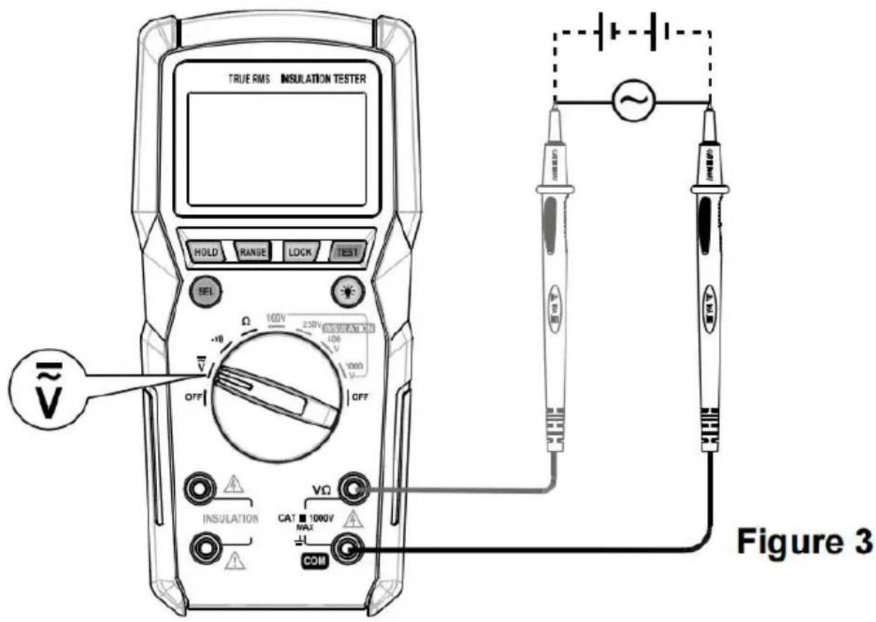
- As shown in Figure 3, connect the black test lead to the terminal and red test lead to the terminal.
- Set the rotary switch to .
- The Meter defaults to AC voltage function, with the icon shown on the display. If you want to measure DC voltage, press the button until the icon appears.
- Connect the test leads across the circuit to be measured.
- Read the display. For DC voltage measurements, the polarity of the red t connection will be indicated as well.
Note: In manual ranging, if the primary display shows OL, it means overrang higher range should be selected.
Measuring Resistance

Warning: Before measurements, disconnect all power to the circuit to be tested and discharge all capacitors thoroughly.
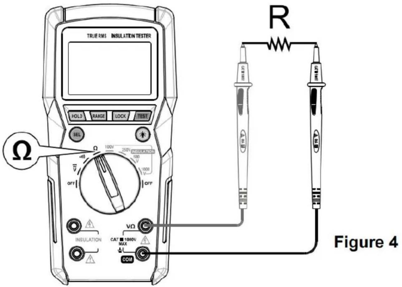
- As shown in Figure 4, connect the black test lead to the COM terminal red test lead to the terminal.
- Set the rotary switchΩ.to
- Connect the test leads across the resistor to be measured.
- Allow the reading to stabilize, then read the display.
Note:
- For measurements >1 M , the Meter may take a few seconds to stabilize readings. This is normal for high resistance measurements.
- If input terminals are open, OL will be shown on the primary display as overrange indication.
- In manual ranging, if the primary display shows OL, it means overrange. higher range should be selected.
Continuity Test

Warning: Before tests, disconnect all power to the circuit to be tested a
discharge all capacitors thoroughly.
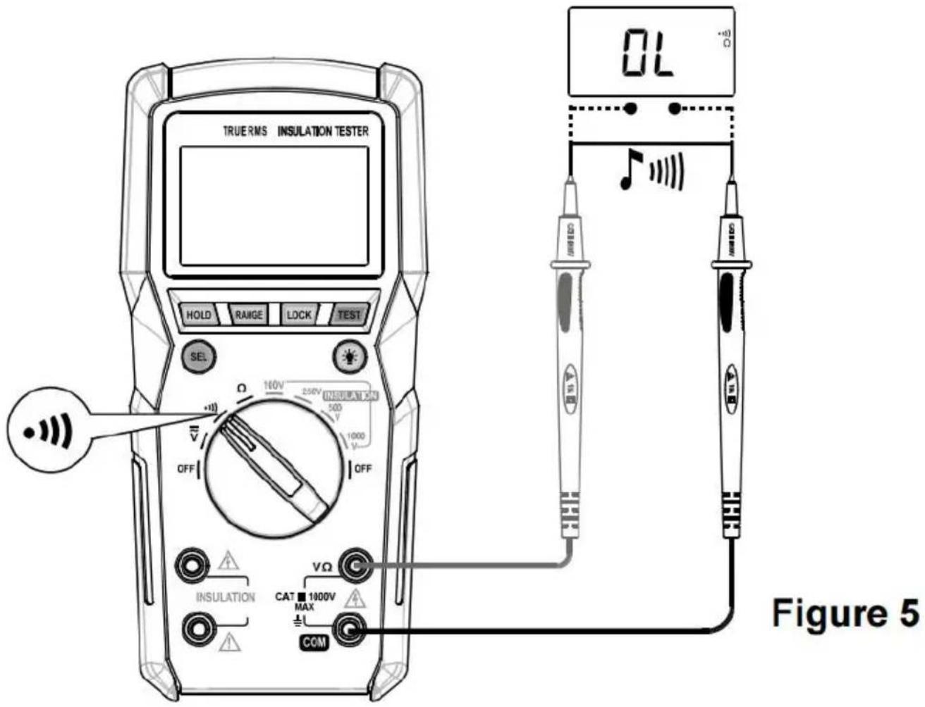
- As shown in Figure 5, connect the black test lead to the COM terminal red test lead to the terminal.
- Set the rotary switch to .
- Connect the test leads across the circuit to be tested.
- If the resistance is less than about 30 , the built-in buzzer will beep.
Testing Insulation

Warning:
- Insulation tests should only be performed on dead circuits.
- Before starting insulation tests, do the followings:
• Make sure that the object under test is not electrically live.
• Make sure that the object under test has been discharged thoroughly.
- Make sure that the rotary switch has been set to the correct switch position
that all the connections are good and firm.
- Once an insulation test starts, the Meter continuously outputs a high voltage avoid electric shock or personal injury, do not touch any naked conductors.
- When an insulation test is ongoing, do not apply any other voltages to the loop.
- During insulation tests, the test leads should be placed separately. Never the test leads together.
- Test duration must not exceed 10 seconds in any of the following conditions
- The measured insulation resistance is less than when the rotary switch is set to 100V.
- The measured insulation resistance is less than 20 ohm the rotary switch is set to 250V.
- The measured insulation resistance is less than 12 when the rotary switch is set to 500V.
-
The measured insulation resistance is less than when the rotary switch is set to 1000V.
-
After completing insulation tests, discharge tested objects thoroughly.
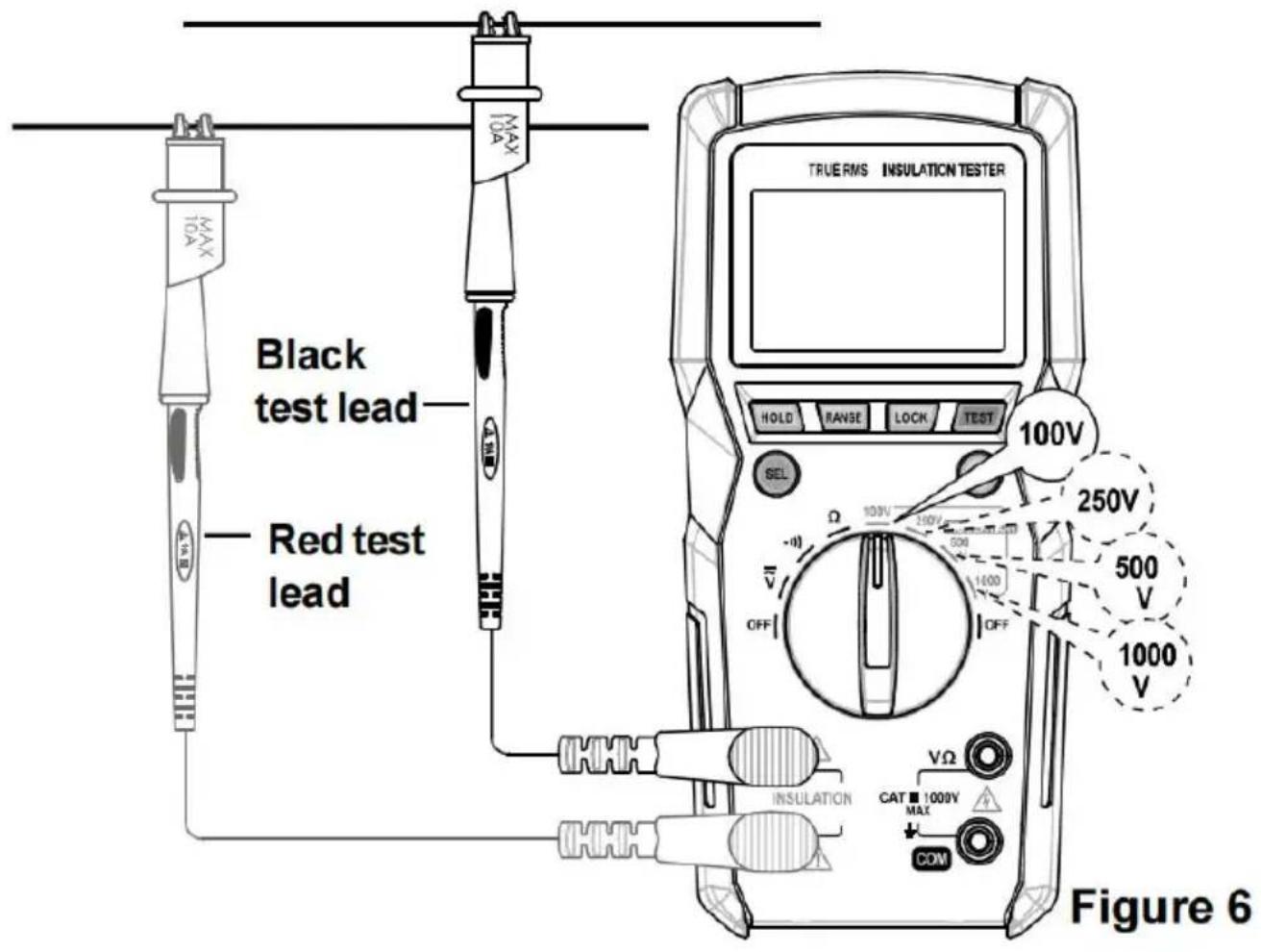
-
As shown in Figure 6, connect the black test lead to the INSULATION n terminal (-) and the red test lead to the INSULATION positive terminal (+).
- Set the rotary switch to a desired test voltage position (100V, 250V, 500V, 1000V) in the INSULATION area.
-
Connect the two test leads to the circuit to be measured.
-
Press and hold the TEST button to start the test. The icon appears as a indication.
During the test:
- The test elapsed time is shown on the lower left display.
- The output test voltage is shown on the lower right display.
- The primary display and the analog bargraph indicate the measured insulation resistance.
- The icon appears to remind you that a high voltage is being output and the extreme caution should be taken.
Note: If you press the LOCK button once and then press the TEST button
the test will remain active until you press the LOCK or TEST button again.
- Read the display.
- Release the TEST button to stop the test.
Note: If both icons and are displayed, stop the test by pressing
the LOCK or TEST button once.
- The circuit under test then discharges through the Meter. To avoid electric and personal injury, do not disconnect the test leads from the circuit under it discharges completely.
Note: The capacitance of the object under test must not exceed 1 uF.
To avoid personal injury, discharge the object under test thoroughly after the completed.
Automatic Power-Off
The Meter automatically turns off if it is not operated for 15 minutes.
Turning the rotary switch to the OFF position first and then switching to a c
position will turn the Meter back on after it is powered off automatically.
To disable automatic power-off, press and hold the button while turning the rotary switch from the OFF setting to other switch settings.
Do not release the button until the Meter completes a full-display.
Note: When an insulation test is ongoing, automatic power-off is disabled.
MAINTENANCE
Except replacing batteries, never attempt to repair or service the Meter.
Store the Meter in a dry place when not in use. Do not store it in an env with intense electromagnetic field.
General Maintenance
Periodically wipe the case with a damp cloth and a little mild detergent.
Do not use abrasives or solvents.
Dirt or moisture in terminals can affect readings. Clean terminals as follows:
-
Set the rotary switch to OFF position and remove the test leads from the
-
Shake out any dirt which may exist in terminals.
-
Soak a new swab with alcohol.
-
Work the swab around in each terminal.
Note: If the Meter fails, check and replace (as needed) batteries, and/or review manual to verify proper use of the Meter.
Batteries Replacement
Warning
To avoid false readings which could lead to possible electric shock of injury, replace the batteries as soon as the low battery indicator app. Turn off the Meter and remove the test leads from the Meter before the battery cover or the case.
To replace the batteries:
-
Remove the screws on the battery cover and then remove the battery cover
-
Replace all the old batteries with six new ones of the same type, making that the polarity connections are correct.
-
Reinstall the battery cover and secure all the screws.
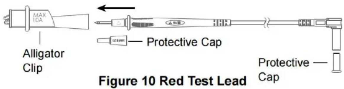
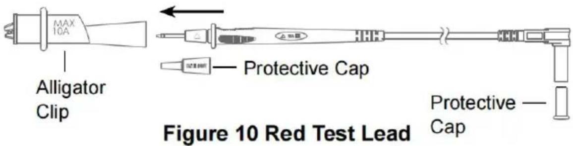
INSTRUCTION FOR THE TEST LEADS
Refer to Figures 7 and 8, remove protective caps at the plugs of the test I before use.
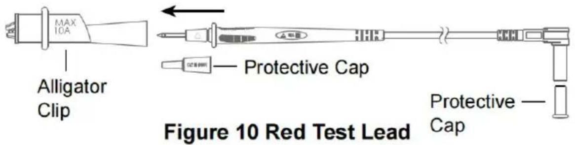
Refer to Figures 9 and 10, remove protective caps at both ends of the test first. Then insert the probes into the metal sockets of the alligator clips.
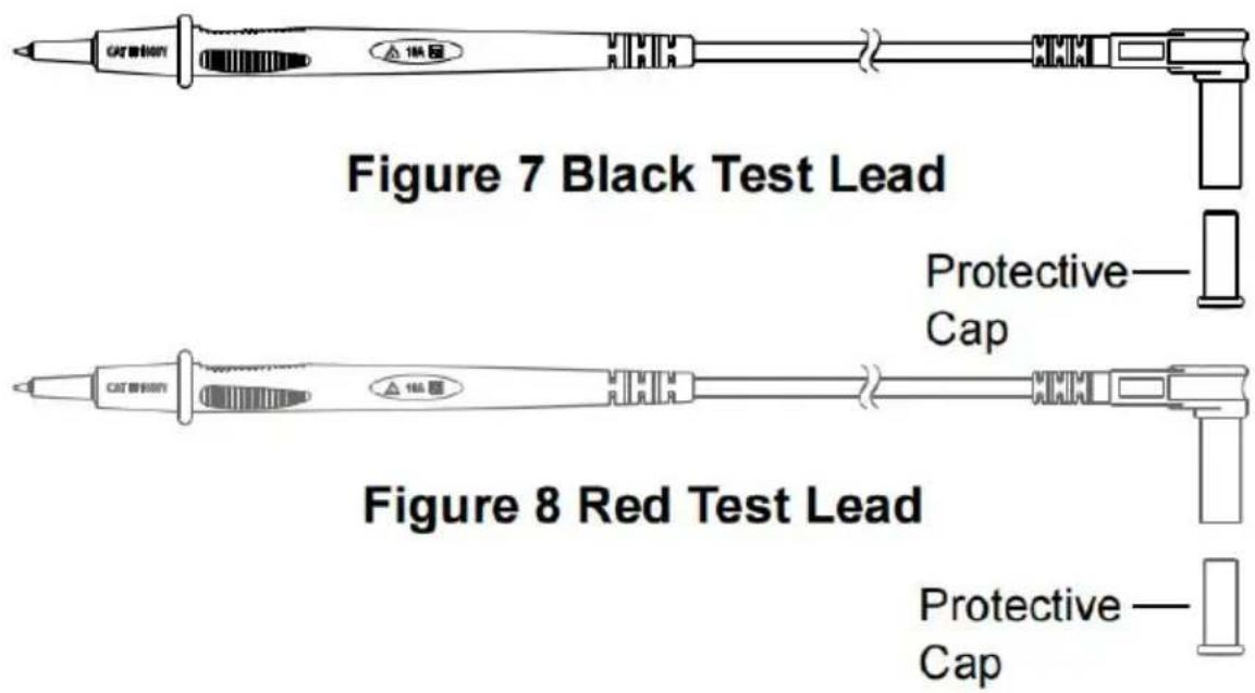
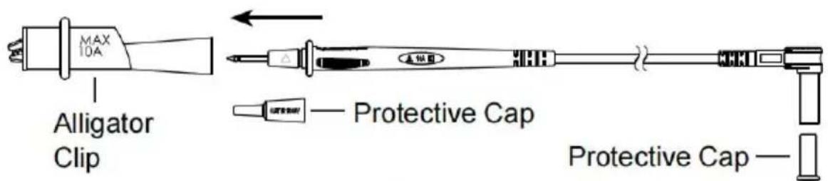
Figure 9 Black Test Lead
Accessories
ACCESSORIES
Test Lead:1 pair
Alligator Clip: 1 pair
Users Manual: 1 piece
DECLARATION
- This manual is subject to change without notice.
- Our company will not take the other responsibilities for any loss.
- The contents of this manual can not be used as the reason to use the Meter for any special application.
Manufacturer: Shanghaimuxinmuyeyouxiangongsi
Address: Shuangchenglu 803nong11hao1602A-1609shi, baoshanqu, shanghai 200000 CN.
Imported to AUS: SIHAO PTY LTD. 1 ROKEVA STREETEASTWOOD NSW 2122 Australia
Imported to USA: Sanven Technology Ltd. Suite 250, 9166 Anaheim Place, Rancho Cucamonga, CA 91730
| UK | REP |
YH CONSULTING LIMITED.
C/O YH Consulting Limited Office 147,
Centurion House, London Road,
Staines-upon-Thames, Surrey, TW18 4AX
| EC | REP |
E-CrossStu GmbH
Mainzer Landstr.69,
60329 Frankfurt am Main.

VEVOR
Affordable. Reliable. Home Improvement.
Product Description and Specifications

| Range | Resolution | Accuracy |
| 4.000V | 0.001V | ± (1% + 5) |
| 40.00V | 0.01V | |
| 400.0V | 0.1V | |
| 1000V | 1V |
| Range | Resolution | Accuracy |
| 4.000V | 0.001V | ± (1% + 5) |
| 40.00V | 0.01V | |
| 400.0V | 0.1V | |
| 1000V | 1V |
| Range | Description | Remark |
| •)) | If the resistance is less than about 30Ω, the built-in buzzer will beep.If the resistance is between 30Ω and 100Ω, the buzzer may or may not beep.If the resistance is more than 100Ω, the buzzer will not beep.If the resistance is more than 410Ω, the primary display will show OL. | Open Circuit Voltage: about 2.1V |
| Test Voltage | Test Range | Resolution | Test Current | Accuracy |
| 100V(0% to 20%) | 0.10MΩ to 40.00MΩ | 0.01MΩ | 1.0mA to 1.2mA@100kΩ | ± (3%+5) |
| 40.0MΩ to 100.0MΩ | 0.1MΩ | |||
| 250V(0% to 20%) | 0.25MΩ to 40.00MΩ | 0.01MΩ | 1.0mA to 1.2mA@250kΩ | |
| 40.0MΩ to 400.0MΩ | 0.1MΩ | |||
| 0.400GΩ to 1.000GΩ | 0.001GΩ | |||
| 500V(0% to 20%) | 0.50MΩ to 40.00MΩ | 0.01MΩ | 1.0mA to 1.2mA@500kΩ | |
| 40.0MΩ to 400.0MΩ | 0.1MΩ | |||
| 0.400GΩ to 2.000GΩ | 0.001GΩ | |||
| 1000V(0% to 20%) | 1.00MΩ to 40.00MΩ | 0.01MΩ | 1.0mA to 1.2mA@1MΩ | |
| 40.0MΩ to 400.0MΩ | 0.1MΩ | |||
| 0.400GΩ to 4.000GΩ | 0.001GΩ | |||
| 4.00GΩ to 10.00GΩ | 0.01GΩ | ± (5%+5) |
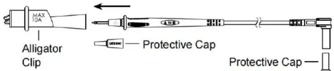
Figure 9 Black Test Lead

Accessories
ACCESSOIRES
C/O YH Consulting Limited Office 147,
Centurion House, London Road,
Staines-upon-Thames, Surrey, TW18 4AX
| EC | REP |
E-CrossStu GmbH
Mainzer Landstr.69,
60329 Frankfurt am Main.

VEVOR
Affordable. Reliable. Home Improvement.
Product Description and Specifications
| Range | Resolution | Accuracy |
| 4.000V | 0.001V | ± (1% + 5) |
| 40.00V | 0.01V | |
| 400.0V | 0.1V | |
| 1000V | 1V |
| Range | Resolution | Accuracy |
| 4.000V | 0.001V | ± (1% + 5) |
| 40.00V | 0.01V | |
| 400.0V | 0.1V | |
| 1000V | 1V |
| Range | Description | Remark |
| •)) | If the resistance is less than about 30Ω, the built-in buzzer will beep.If the resistance is between 30Ω and 100Ω, the buzzer may or may not beep.If the resistance is more than 100Ω, the buzzer will not beep.If the resistance is more than 410Ω, the primary display will show OL. | Open Circuit Voltage: about 2.1V |
Isolationswiderstand
| Test Voltage | Test Range | Resolution | Test Current | Accuracy |
| 100V(0% to 20%) | 0.10MΩ to 40.00MΩ | 0.01MΩ | 1.0mA to 1.2mA@100kΩ | ± (3%+5) |
| 40.0MΩ to 100.0MΩ | 0.1MΩ | |||
| 250V(0% to 20%) | 0.25MΩ to 40.00MΩ | 0.01MΩ | 1.0mA to 1.2mA@250kΩ | |
| 40.0MΩ to 400.0MΩ | 0.1MΩ | |||
| 0.400GΩ to 1.000GΩ | 0.001GΩ | |||
| 500V(0% to 20%) | 0.50MΩ to 40.00MΩ | 0.01MΩ | 1.0mA to 1.2mA@500kΩ | |
| 40.0MΩ to 400.0MΩ | 0.1MΩ | |||
| 0.400GΩ to 2.000GΩ | 0.001GΩ | |||
| 1000V(0% to 20%) | 1.00MΩ to 40.00MΩ | 0.01MΩ | 1.0mA to 1.2mA@1MΩ | |
| 40.0MΩ to 400.0MΩ | 0.1MΩ | |||
| 0.400GΩ to 4.000GΩ | 0.001GΩ | |||
| 4.00GΩ to 10.00GΩ | 0.01GΩ | ± (5%+5) |
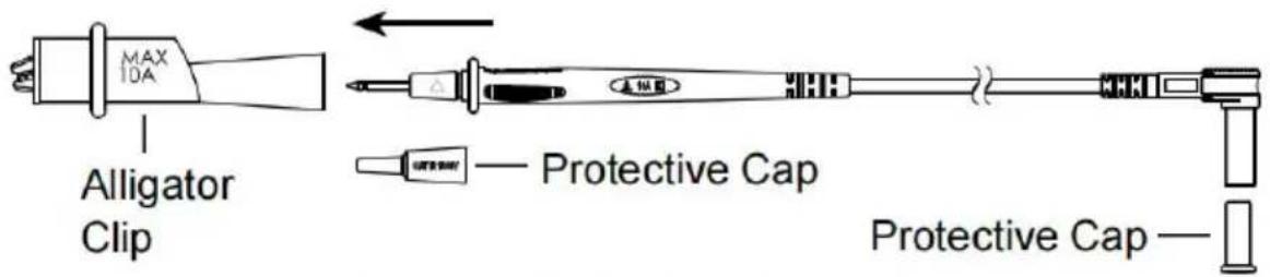
Figure 9 Black Test Lead
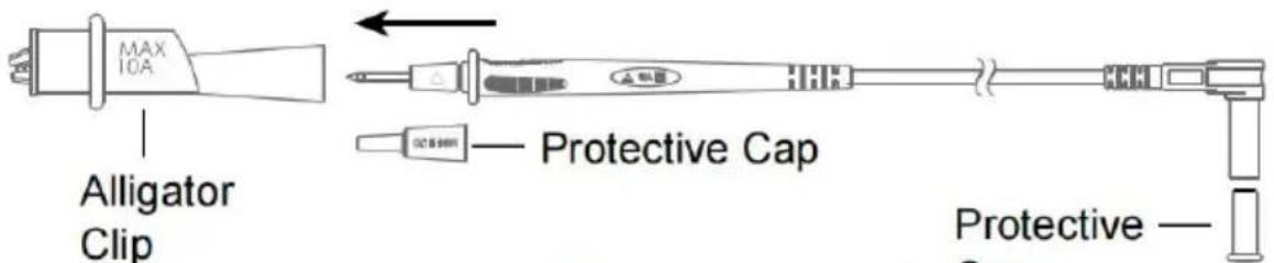
Figure 10 Red Test Lead
Accessories
ZUBEHÖR
Messleitung: 1 Paar
Krokodilklemme: 1 Paar
C/O YH Consulting Limited Office 147,
Centurion House, London Road,
Staines-upon-Thames, Surrey, TW18 4AX
| EC | REP |
E-CrossStu GmbH
Mainzer Landstr.69,
60329 Frankfurt am Main.

VEVOR
Affordable. Reliable. Home Improvement.
Product Description and Specifications

| Range | Resolution | Accuracy |
| 4.000V | 0.001V | ± (1% + 5) |
| 40.00V | 0.01V | |
| 400.0V | 0.1V | |
| 1000V | 1V |
| Range | Resolution | Accuracy |
| 4.000V | 0.001V | ± (1% + 5) |
| 40.00V | 0.01V | |
| 400.0V | 0.1V | |
| 1000V | 1V |
| Range | Description | Remark |
| •)) | If the resistance is less than about 30Ω, the built-in buzzer will beep.If the resistance is between 30Ω and 100Ω, the buzzer may or may not beep.If the resistance is more than 100Ω, the buzzer will not beep.If the resistance is more than 410Ω, the primary display will show OL. | Open Circuit Voltage: about 2.1V |
| Test Voltage | Test Range | Resolution | Test Current | Accuracy |
| 100V(0% to 20%) | 0.10MΩ to 40.00MΩ | 0.01MΩ | 1.0mA to 1.2mA@100kΩ | ± (3%+5) |
| 40.0MΩ to 100.0MΩ | 0.1MΩ | |||
| 250V(0% to 20%) | 0.25MΩ to 40.00MΩ | 0.01MΩ | 1.0mA to 1.2mA@250kΩ | |
| 40.0MΩ to 400.0MΩ | 0.1MΩ | |||
| 0.400GΩ to 1.000GΩ | 0.001GΩ | |||
| 500V(0% to 20%) | 0.50MΩ to 40.00MΩ | 0.01MΩ | 1.0mA to 1.2mA@500kΩ | |
| 40.0MΩ to 400.0MΩ | 0.1MΩ | |||
| 0.400GΩ to 2.000GΩ | 0.001GΩ | |||
| 1000V(0% to 20%) | 1.00MΩ to 40.00MΩ | 0.01MΩ | 1.0mA to 1.2mA@1MΩ | |
| 40.0MΩ to 400.0MΩ | 0.1MΩ | |||
| 0.400GΩ to 4.000GΩ | 0.001GΩ | |||
| 4.00GΩ to 10.00GΩ | 0.01GΩ | ± (5%+5) |
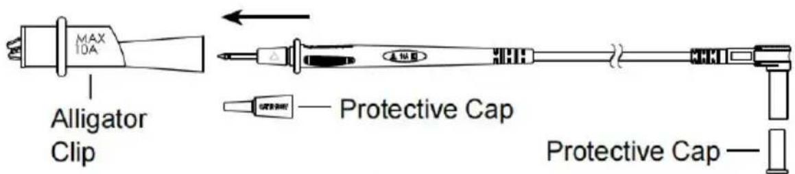
Figure 9 Black Test Lead
Accessories
ACCESSORI
Importato in AUS: SIHAO PTY LTD. 1 ROKEVA STREETEASTWOOD NSW 2122 Australia
Importato negli USA: Sanven Technology Ltd. Suite 250, 9166 Anaheim Place, Rancho Cucamonga, CA 91730
| UK | REP |
YH CONSULTING LIMITED.
C/O YH Consulting Limited Office 147,
Centurion House, London Road,
Staines-upon-Thames, Surrey, TW18 4AX
| EC | REP |
E-CrossStu GmbH
Mainzer Landstr.69,
60329 Frankfurt am Main.

VEVOR
Affordable. Reliable. Home Improvement.
Product Description and Specifications

| Range | Resolution | Accuracy |
| 4.000V | 0.001V | ± (1% + 5) |
| 40.00V | 0.01V | |
| 400.0V | 0.1V | |
| 1000V | 1V |
| Range | Resolution | Accuracy |
| 4.000V | 0.001V | ± (1% + 5) |
| 40.00V | 0.01V | |
| 400.0V | 0.1V | |
| 1000V | 1V |
| Range | Description | Remark |
| •)) | If the resistance is less than about 30Ω, the built-in buzzer will beep.If the resistance is between 30Ω and 100Ω, the buzzer may or may not beep.If the resistance is more than 100Ω, the buzzer will not beep.If the resistance is more than 410Ω, the primary display will show OL. | Open Circuit Voltage: about 2.1V |
| Test Voltage | Test Range | Resolution | Test Current | Accuracy |
| 100V(0% to 20%) | 0.10MΩ to 40.00MΩ | 0.01MΩ | 1.0mA to 1.2mA@100kΩ | ± (3%+5) |
| 40.0MΩ to 100.0MΩ | 0.1MΩ | |||
| 250V(0% to 20%) | 0.25MΩ to 40.00MΩ | 0.01MΩ | 1.0mA to 1.2mA@250kΩ | |
| 40.0MΩ to 400.0MΩ | 0.1MΩ | |||
| 0.400GΩ to 1.000GΩ | 0.001GΩ | |||
| 500V(0% to 20%) | 0.50MΩ to 40.00MΩ | 0.01MΩ | 1.0mA to 1.2mA@500kΩ | |
| 40.0MΩ to 400.0MΩ | 0.1MΩ | |||
| 0.400GΩ to 2.000GΩ | 0.001GΩ | |||
| 1000V(0% to 20%) | 1.00MΩ to 40.00MΩ | 0.01MΩ | 1.0mA to 1.2mA@1MΩ | |
| 40.0MΩ to 400.0MΩ | 0.1MΩ | |||
| 0.400GΩ to 4.000GΩ | 0.001GΩ | |||
| 4.00GΩ to 10.00GΩ | 0.01GΩ | ± (5%+5) |
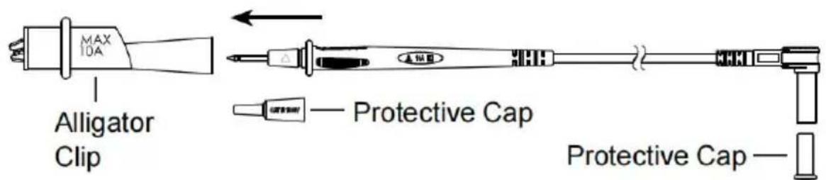
Figure 9 Black Test Lead
Accessories
ACCESORIOS
C/O YH Consulting Limited Office 147,
Centurion House, London Road,
Staines-upon-Thames, Surrey, TW18 4AX
| EC | REP |
E-CrossStu GmbH
Mainzer Landstr.69,
60329 Frankfurt am Main.

VEVOR
Affordable. Reliable. Home Improvement.
Product Description and Specifications

| Range | Resolution | Accuracy |
| 4.000V | 0.001V | ± (1% + 5) |
| 40.00V | 0.01V | |
| 400.0V | 0.1V | |
| 1000V | 1V |
| Range | Resolution | Accuracy |
| 4.000V | 0.001V | ± (1% + 5) |
| 40.00V | 0.01V | |
| 400.0V | 0.1V | |
| 1000V | 1V |
| Range | Description | Remark |
| •)) | If the resistance is less than about 30Ω, the built-in buzzer will beep.If the resistance is between 30Ω and 100Ω, the buzzer may or may not beep.If the resistance is more than 100Ω, the buzzer will not beep.If the resistance is more than 410Ω, the primary display will show OL. | Open Circuit Voltage: about 2.1V |
| Test Voltage | Test Range | Resolution | Test Current | Accuracy |
| 100V(0% to 20%) | 0.10MΩ to 40.00MΩ | 0.01MΩ | 1.0mA to 1.2mA@100kΩ | ± (3%+5) |
| 40.0MΩ to 100.0MΩ | 0.1MΩ | |||
| 250V(0% to 20%) | 0.25MΩ to 40.00MΩ | 0.01MΩ | 1.0mA to 1.2mA@250kΩ | |
| 40.0MΩ to 400.0MΩ | 0.1MΩ | |||
| 0.400GΩ to 1.000GΩ | 0.001GΩ | |||
| 500V(0% to 20%) | 0.50MΩ to 40.00MΩ | 0.01MΩ | 1.0mA to 1.2mA@500kΩ | |
| 40.0MΩ to 400.0MΩ | 0.1MΩ | |||
| 0.400GΩ to 2.000GΩ | 0.001GΩ | |||
| 1000V(0% to 20%) | 1.00MΩ to 40.00MΩ | 0.01MΩ | 1.0mA to 1.2mA@1MΩ | |
| 40.0MΩ to 400.0MΩ | 0.1MΩ | |||
| 0.400GΩ to 4.000GΩ | 0.001GΩ | |||
| 4.00GΩ to 10.00GΩ | 0.01GΩ | ± (5%+5) |
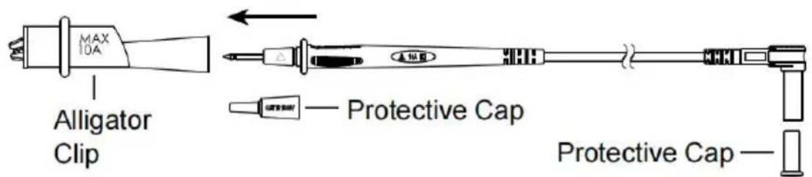
Figure 9 Black Test Lead
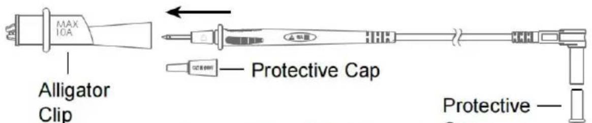
Figure 10 Red Test Lead
Accessories
AKCESORIA
STREETEASTWOOD NSW 2122 Australia
Importowane do USA: Sanven Technology Ltd. Suite 250, 9166 Anar Place, Rancho Cucamonga, CA 91730
| UK | REP |
YH CONSULTING LIMITED.
C/O YH Consulting Limited Office 147,
Centurion House, London Road,
Staines-upon-Thames, Surrey, TW18 4AX
| EC | REP |
E-CrossStu GmbH
Mainzer Landstr.69,
60329 Frankfurt am Main.

VEVOR
Affordable. Reliable. Home Improvement.
True Rms-isolatietester
Model: SS103
Model: SS103
Product Description and Specifications

| Range | Resolution | Accuracy |
| 4.000V | 0.001V | ± (1% + 5) |
| 40.00V | 0.01V | |
| 400.0V | 0.1V | |
| 1000V | 1V |
Ingangsimpedantie: >1M Ω
| Range | Resolution | Accuracy |
| 4.000V | 0.001V | ± (1% + 5) |
| 40.00V | 0.01V | |
| 400.0V | 0.1V | |
| 1000V | 1V |
| Range | Description | Remark |
| •)) | If the resistance is less than about 30Ω, the built-in buzzer will beep.If the resistance is between 30Ω and 100Ω, the buzzer may or may not beep.If the resistance is more than 100Ω, the buzzer will not beep.If the resistance is more than 410Ω, the primary display will show OL. | Open Circuit Voltage: about 2.1V |
Isolatieweerstand
| Test Voltage | Test Range | Resolution | Test Current | Accuracy |
| 100V(0% to 20%) | 0.10MΩ to 40.00MΩ | 0.01MΩ | 1.0mA to 1.2mA@100kΩ | ± (3%+5) |
| 40.0MΩ to 100.0MΩ | 0.1MΩ | |||
| 250V(0% to 20%) | 0.25MΩ to 40.00MΩ | 0.01MΩ | 1.0mA to 1.2mA@250kΩ | |
| 40.0MΩ to 400.0MΩ | 0.1MΩ | |||
| 0.400GΩ to 1.000GΩ | 0.001GΩ | |||
| 500V(0% to 20%) | 0.50MΩ to 40.00MΩ | 0.01MΩ | 1.0mA to 1.2mA@500kΩ | |
| 40.0MΩ to 400.0MΩ | 0.1MΩ | |||
| 0.400GΩ to 2.000GΩ | 0.001GΩ | |||
| 1000V(0% to 20%) | 1.00MΩ to 40.00MΩ | 0.01MΩ | 1.0mA to 1.2mA@1MΩ | |
| 40.0MΩ to 400.0MΩ | 0.1MΩ | |||
| 0.400GΩ to 4.000GΩ | 0.001GΩ | |||
| 4.00GΩ to 10.00GΩ | 0.01GΩ | ± (5%+5) |
C/O YH Consulting Limited Office 147,
Centurion House, London Road,
Staines-upon-Thames, Surrey, TW18 4AX
| EC | REP |
E-CrossStu GmbH
Mainzer Landstr.69,
60329 Frankfurt am Main.

VEVOR
Affordable. Reliable. Home Improvement.
True RMS-isoleringstestare
Modell: SS103
Modell: SS103

Product Description and Specifications

| Range | Resolution | Accuracy |
| 4.000V | 0.001V | ± (1% + 5) |
| 40.00V | 0.01V | |
| 400.0V | 0.1V | |
| 1000V | 1V |
| Range | Resolution | Accuracy |
| 4.000V | 0.001V | ± (1% + 5) |
| 40.00V | 0.01V | |
| 400.0V | 0.1V | |
| 1000V | 1V |
| Range | Description | Remark |
| •)) | If the resistance is less than about 30Ω, the built-in buzzer will beep.If the resistance is between 30Ω and 100Ω, the buzzer may or may not beep.If the resistance is more than 100Ω, the buzzer will not beep.If the resistance is more than 410Ω, the primary display will show OL. | Open Circuit Voltage: about 2.1V |
Isoleringsmotständ
| Test Voltage | Test Range | Resolution | Test Current | Accuracy |
| 100V(0% to 20%) | 0.10MΩ to 40.00MΩ | 0.01MΩ | 1.0mA to 1.2mA@100kΩ | ± (3%+5) |
| 40.0MΩ to 100.0MΩ | 0.1MΩ | |||
| 250V(0% to 20%) | 0.25MΩ to 40.00MΩ | 0.01MΩ | 1.0mA to 1.2mA@250kΩ | |
| 40.0MΩ to 400.0MΩ | 0.1MΩ | |||
| 0.400GΩ to 1.000GΩ | 0.001GΩ | |||
| 500V(0% to 20%) | 0.50MΩ to 40.00MΩ | 0.01MΩ | 1.0mA to 1.2mA@500kΩ | |
| 40.0MΩ to 400.0MΩ | 0.1MΩ | |||
| 0.400GΩ to 2.000GΩ | 0.001GΩ | |||
| 1000V(0% to 20%) | 1.00MΩ to 40.00MΩ | 0.01MΩ | 1.0mA to 1.2mA@1MΩ | |
| 40.0MΩ to 400.0MΩ | 0.1MΩ | |||
| 0.400GΩ to 4.000GΩ | 0.001GΩ | |||
| 4.00GΩ to 10.00GΩ | 0.01GΩ | ± (5%+5) |
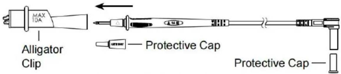
Figure 9 Black Test Lead
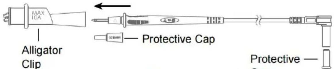
Figure 10 Red Test Lead
Accessories
TILLBEHÖR
Testsladd: 1 par
C/O YH Consulting Limited Office 147,
Centurion House, London Road,
Staines-upon-Thames, Surrey, TW18 4AX
| EC | REP |
E-CrossStu GmbH
Mainzer Landstr.69,
60329 Frankfurt am Main.