SS101 - Multimeter Vevor - Free user manual and instructions
Find the device manual for free SS101 Vevor in PDF.

| Product Type | Digital Multimeter |
| Brand | Vevor |
| Model | SS101 |
| Dimensions | 170 mm x 86 mm x 40 mm |
| Weight | Approximately 183 g (without battery or case) |
| Power Supply | 9 V battery (type 6F22 or equivalent) |
| Display | LCD 3 3/4 digits (4000 counts) |
| Main Functions | DC/AC voltage, DC/AC current, resistance, continuity, diode, capacitance, frequency, duty cycle, temperature |
| Special Functions | True RMS, auto/manual ranging, Data Hold, MAX/MIN recording, relative measurement, backlight, flashlight, auto power off |
| Safety Category | CAT II 600 V |
| Protection Rating | IP20 |
| Overload Protection | Fuses 500 mA/250 V (mA input) and 10 A/250 V (10A input) |
| Maintenance and Cleaning | Wipe with a damp cloth and mild detergent; clean the terminals with alcohol and a cotton swab |
| Spare Parts and Repairability | Fast-blow fuses (500 mA/250 V and 10 A/250 V), type K thermocouple, test leads |
| Warranty | 1 year against defects in materials and workmanship |
| Compliance | FCC Part 15 (Class B), European Directive 2012/19/EU (WEEE) |
Frequently Asked Questions - SS101 Vevor
User questions about SS101 Vevor
0 question about this device. Answer the ones you know or ask your own.
Ask a new question about this device
Download the instructions for your Multimeter in PDF format for free! Find your manual SS101 - Vevor and take your electronic device back in hand. On this page are published all the documents necessary for the use of your device. SS101 by Vevor.
USER MANUAL SS101 Vevor
Affordable. Reliable. Home Improvement.
Digital Multimeter
Model:SS101
VEVOR
Affordable. Reliable. Home Improvement.
Digital Multimeter
Model:SS101
This is the original instruction, please read all manual instructions carefully before operating. VEVOR reserves a clear interpretation of our user manual. The appearance of the product shall be subject to the product y received. Please forgive us that we won't inform you again if there are a technology or software updates on our product.
 | Warning-To reduce the risk of injury, user must read instruction manual carefully. |
 | CORRECT DISPOSALThis product is subject to the provision of european Directive 2012/19/EU. The symbol showing a wheelie bin crossed through indicates that the product requires separate refuse collection in European Union. This applies to the product and all accessories marked with this symbol. Products marked as such may not be discarded with normal domestic waste, but must be taken to acollection point for recycling electrical and electronic devices. |
| FCC Information | FCC Information:CAUTION: Changes or modifications not expressly approved by the party responsible for compliance could void the user's auto to operate the equipment!This device complies with Part 15 of the FCC Rules. Operatic subject to the following two conditions:1) This product may cause harmful interference.2) This product must accept any interference received, including interference that may cause undesired operation.WARNING: Changes or modifications to this product not expre approved by the party.responsible for compliance could void the user's authority to operate the product.Note: This product has been tested and found to comply with limits for a Class B digital device pursuant to Part 15 of the Rules, These limits are designed to provide reasonable protec against harmful interference in a residential installation.This product generates, uses and can radiate radio frequency energy, and if not installed and used in accordance with the instructions, may cause harmful interference to radio communications. However, there is no guarantee that interfered will not occur in a particular installation. If this product does it harmful interference to radio or television reception,which candetermined by turning the product off and on, the user is encouraged to try to correct the interference by one or more following measures.· Reorient or relocate the receiving antenna.· Increase the distance between the product and receiver.· Connect the product to an outlet on a circuit different from which the receiver is connected.· Consult the dealer or an experienced radio/TV technician for assistance. |
WARRANTY
This instrument is warranted to be free from defects in material and workmanship for a period of one year. Any instrument found defective within one year from the delivery date and returned to the factory with transportation charges prepaid, will be repaired, adjusted, or replaced at no charge to the original purchaser. This warranty does not cover expandable items such as batteries. If the defect has been caused by a misuse or abnormal operating condition, the repair will be billed at a nominal cost.
INTRODUCTION
The Product is a compact ^3/4 digit true-RMS autorange digital multimeter. It is designed to measure DC and AC voltage, DC and AC current, resistance, continuity, diode, capacitance, frequency, duty cycle, and temperature.
The Meter features MAX MIN recording, Relative measurement, auto/manual ranging, Data Hold, backlight, low battery indication, over range indication, automatic power-off, flashlight, etc. It is easy to operate and is a useful test tool.
SAFETY INFORMATION
The Meter complies with Measurement Categories II (CAT II 600V) and Pollution Degree 2.

WARNING
To avoid possible electric shock or personal injury, follow these guidelines:
- Do not use the Meter if it is damaged. Before you use the Meter, inspect the
Pay particular attention to the insulation surrounding the connectors.
- Inspect the test leads for damaged insulation or exposed metal. Check the test leads for continuity. Replace damaged test leads before you use the Meter.
- Do not use the Meter if it operates abnormally. Protection may be impaired. When in doubt, have the Meter serviced.
- Do not operate the Meter around explosive gas, vapor, or dust.
- Do not apply more than the rated voltage, as marked on the Meter, between terminals or between any terminal and earth ground.
- Before use, verify the Meter's operation by measuring a known voltage.
- When servicing the Meter, use only specified replacement parts.
- When using the probes, keep your fingers behind the finger guards on the probes.
- Use caution when working with voltages above 30V ac rms, 42V ac peak, or 6 dc. Such voltages pose a shock hazard.
- When making connections, connect the common test lead before you connect the live test lead. When you disconnect test leads, disconnect the live test lead first.
- Remove the test leads from the Meter before you open the battery cover or the case.
- Do not operate the Meter with the battery cover or portions of the case removal or loosened.
• To avoid false readings which could lead to possible electric shock or personal
injury, replace the battery as soon as the low battery indicator appears.
- Do not use the Meter in a manner not specified by this manual, or the safety features of the Meter may be impaired.
- When measuring current, turn off circuit power before connecting the Meter in the circuit. Remember to place the Meter in series with the circuit.
- When in Relative mode (is displayed) or in MIN mode (MIN is displayed), caution must be used as hazardous voltages may be present.
- Do not operate the Meter if your hand or the Meter is wet.
- Do not touch any naked conductor with hand or skin, and do not ground yours
- Remaining endangerment:
When an input terminal is connected to a dangerous live potential, it is to be no that this potential at all other terminals can occur!
- CAT II - Measurement Category II is for measurements performed on circuits directly connected to low voltage installation. Examples are measurements on household appliances, portable tools and similar equipment.
Do not use the Meter for measurements within Measurement Categories III and I'
Caution
To avoid possible damage to the Meter or to the equipment under test, follow th guidelines:
- Disconnect circuit power and discharge all capacitors thoroughly before testing resistance, continuity, diode, capacitance or temperature.
- Use the proper terminals, function and range for your measurements.
- Before measuring current, check the Meter's fuses.
- Before turning the rotary switch to change function/range, remove the test leads from the circuit under test.
Symbols
 | Both Alternating and Direct current |
 | Fuse |
 | Caution, risk of danger, refer to the operating manual before use |
 | Caution, risk of electric shock. |
 | Earth (ground) Terminal |
 | Conforms to European Union directives |
 | The equipment is protected throughout by double insulation or reinforced insulation. |
Product Description and Specifications

Read all safety warnings and all instructions. Failure to follow the warnings and instructions may result in electric shock, fire and/or serious injury.
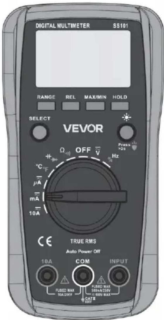
FRONT PANEL
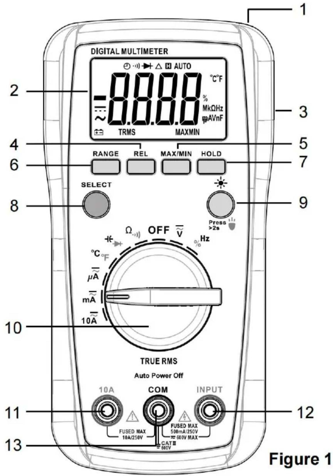
- Flashlight
- Display
3 ^3/4 -digit LCD. - Holster
- " REL " Button
Used to enter/exit Relative mode.
- " MAX/MIN " Button
Used to enter/exit MAX MIN recording mode as well as to switch the displayed reading between maximum and minimum.
- " RANGE " Button
Used to switch between autoranging and manual ranging as well as to select a desired manual range.
- " HOLD " Button
Used to enable/disable Data Hold.
- " SELECT " Button
Used to switch between:
a. DC and AC voltage functions.
b. DC and AC current functions.
c. Resistance and continuity functions.
d. Capacitance and diode functions.
e. Frequency and duty cycle functions.
f. Celsius and Fahrenheit functions.
-
"7" "Button
-
Short press to turn on/off the backlight. The backlight goes off after approximating 30 seconds.
-
Long press for more than 2 seconds to turn on/off the flashlight.
-
Rotary Switch
Used to select the desired function/range as well as to turn on/off the Meter. Wh the Meter is not in use, set this switch in the OFF position.
- " 10A " Terminal
Plug-in connector for the red test lead for 400mA to 10A current measurements.
- " INPUT " Terminal
Plug-in connector for the red test lead for all measurements except current
(>400mA) and temperature measurements.
For temperature measurements, this terminal is for the positive plug of the K Typ thermocouple.
13. " COM " Terminal
Plug-in connector for the black test lead for all measurements except temperature measurements.
For temperature measurements, this terminal is for the negative plug of the K Ty thermocouple.
UNDERSTANDING THE DISPLAY
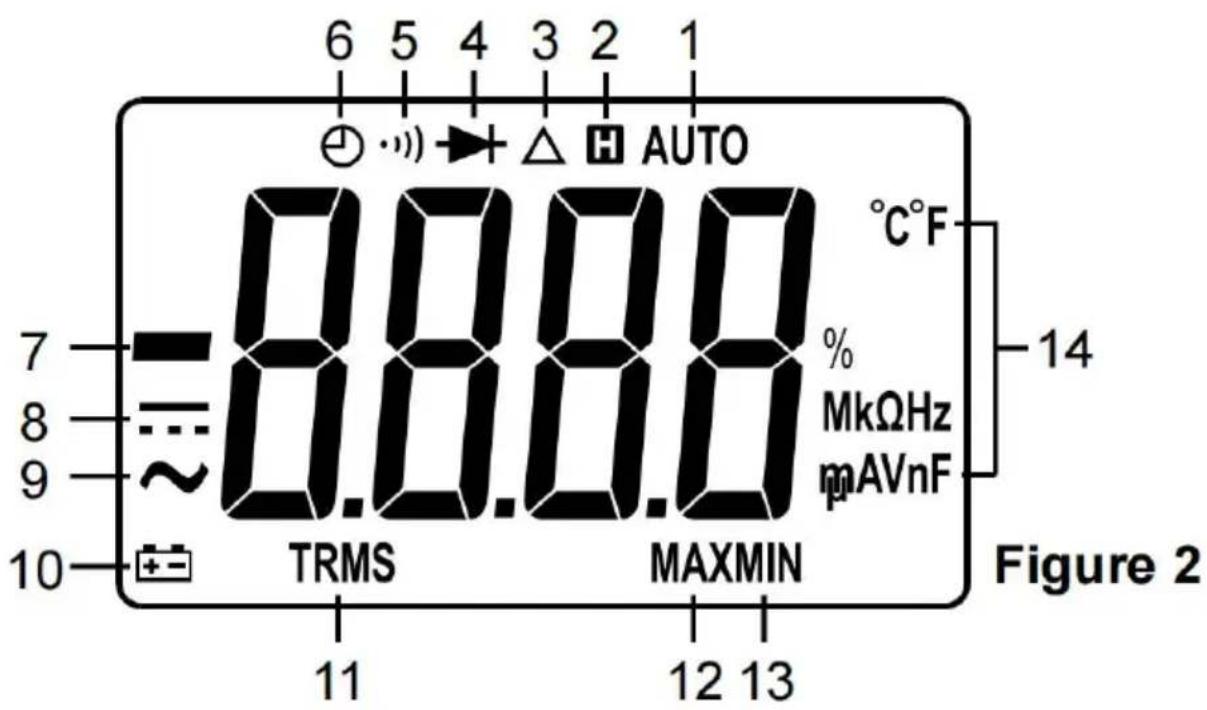
Explanations:
| NO. | Symbol | Description |
| 1 |  | Autoranging |
| 2 |  | Data Hold is enabled. |
| 3 | [GABH] | The Meter is in Relative mode. |
| 4 |  | Diode test is selected |
| 5 |  | Continuity test is selected. |
| 6 |  | Automatic power-off is enabled. |
| 7 |  | -Negative sign |
| 8 |  | DC |
| 9 |  | AC |
| 10 |  | The battery is low and should be replaced immediat |
| 11 |  | True-RMS reading is being displayed. |
| 12 |  | The maximum reading is being displayed. |
| 13 |  | The minimum reading is being displayed. |
14. Units
| mV, V | Units of voltagemV: Millivolt; V: Volt 1V = ^3 10nV |
| μA, mA, A | Units of currentμA: Microamp; mA: Milliamp; A: Ampere 1A ^3 =mA0 = 10μA |
| Ω , kΩ , MΩnF, μF | Units of resistanceΩ : Ohm; k Ω : Kilohm; M Ω : Megohm 1M ^3 Ω=10ΩUnits of capacitancenF: Nanofarad; μF: Microfarad 1μF = 110 F |
| °C, °F | Units of temperature°C: Celsius degree; °F: Fahrenheit degreef (°F) = 32 + 1.8 X c (°C) |
| Hz, kHz | Units of frequencyHz: Hertz; kHz: Kilohertz 1kHz = 110 Hz |
| % | Unit of duty cycle %: Percent |
GENERAL SPECIFICATION
Display: 3^3/4 -digit LCD
Negative Polarity Indication: Negative sign shown on the display
Overrange Indication: OL or -OL shown on the display
Sampling Rate: About 2 to 3 times/sec
IP Degree: IP20
Temperature Coefficient: 0.1 x (specified accuracy) /°C (<18°C or >28°C)
Operating Environment: Temperature: 0°C to 40°C
Relative Humidity: <75%
Storage Environment: Temperature: - 10°C to 60°C
Relative Humidity: <85%
Operating Altitude: 0 to 2000 meters
Battery: 9V battery, 6F22 or equivalent, 1 piece
Low Battery Indication: shown on the display
Size: 170mm x 86mm x 40mm
Weight: About 183g (without battery and holster)
SPECIFICATION
Accuracy is specified for a period of one year after calibration and at 18^ C to 28 with humidity < 75%RH.
Accuracy specifications take the form of:
± [% of Reading]+[number of Least Significant Digits])
Except the ranges specified specially, accuracy is specified from 5 % to 100% of range.
DC Voltage
| Range | Resolution | Accuracy | Overrange Indication |
| 400mV | 0.1mV | ± (0.8% + 5) | OL is displayed. |
| 4V | 0.001V | ± (0.5% + 5) | |
| 40V | 0.01V | ± (1.0% + 5) | |
| 400V | 0.1V | ||
| 600V | 1V | ____ [1] |
Input Impedance: About 10MΩ
Max. Allowable Input Voltage: 600V dc/ac
[1] When the measured voltage ≥ 600V, the built-in buzzer beeps. When the voltage is >660V, the display shows OL.
AC Voltage
| Range | Resolution | Accuracy | Overrange Indication |
| 4V | 0.001V | ± ( 1.5% + 5) | OL is displayed. |
| 40V | 0.01V | ||
| 400V | 0.1V | ||
| 600V | 1V | ± (2.0% + 5) | [1] |
Input Impedance: About 10MΩ
Overload Protection: 600V dc/ac
Max. Allowable Input Voltage: 600V ac
Reading: True rms
Frequency Range: 40Hz to 1kHz (Note: Except for sine wave signal and triangular wave signal measurements, accuracy specifications for ac voltage measurements do not apply to signals with frequency >200Hz.)
[1] When the measured voltage is ≥600V , the built-in buzzer beeps. When the voltage is >660V, the display shows OL.
DC Current
| Range | Resolution | Accuracy | Overrange Indication |
| 400μA | 0.1μA | ± (1.0% + 5) | ____[1] |
| 4000μA | 1μA | ||
| 40mA | 0.01mA | ____[2] | |
| 400mA | 0.1mA | ||
| 4A | 0.001A | ± (2.0% + 5) | ____[3] |
| 10A | 0.01A |
Overload Protection:
500 mA/ 250V FAST fuse for INPUT terminal inputs
10A/250V FAST fuse for 10A terminal inputs
Max. Allowable Input Current:
INPUT terminal: 400mA
10A terminal: 10A (For inputs >2A: duration <10 seconds, interval > 15 minutes)
[1] When the measured current is > 4400uA, the display shows OL.
[2] When the measured current is > 440mA, the display shows OL.
[3] When the measured current is ≥ 10A, the built-in buzzer beeps. When the current is > 11A, the display shows OL.
AC Current
| Range | Resolution | Accuracy | Overrange Indication |
| 400μA | 0.1μA | ± ( 1.5% + 5) | ____ [1] |
| 4000μA | 1μA | ||
| 40mA | 0.01mA | ____ [2] | |
| 400mA | 0. 1mA | ||
| 4A | 0.001A | ± (2.0% + 5) | ____ [3] |
| 10A | 0.01A |
Overload Protection:
500mA/ 250V FAST fuse for INPUT terminal inputs
10A/250V FAST fuse for 10A terminal inputs
Max. Allowable Input Current:
INPUT terminal: 400 mA
10A terminal: 10A (For inputs >2A: duration <10 seconds, interval > 15 minutes)
Reading: True rms
Frequency Range: 40Hz to 1kHz (Note: Except for sine wave signal and triangular wave signal measurements, accuracy specifications for ac current measurements do not apply to signals with frequency >200Hz.)
[1] When the measured current is > 4400uA, the display shows OL.
[2] When the measured current is > 440mA, the display shows OL.
[3] When the measured current is ≥10A , the built-in buzzer beeps. When the current is >11A, the display shows OL.
Resistance
| Range | Resolution | Accuracy | Overrange Indication |
| 400Ω | 0.1Ω | ± (1.2% + 5) | ____[1] |
| 4kΩ | 0.001kΩ | ||
| 40kΩ | 0.01kΩ | ||
| 400kΩ | 0. 1kQΩ | ||
| 4MΩ | 0.001MΩ | ||
| 40MΩ | 0.01MΩ | ± (2.0% + 10) | |
| 50MΩ | 0.1MΩ | ± (2.8% + 10) |
Open Circuit Voltage: about 0.65V
[1] When the measured resistance is >55MΩ, the display shows OL.
Continuity
| Range | Description | Remark |
| The built-in buzzer will beep if the resistance is less than about 30Ω. If the resistance is between 30Ω and 100 the buzzer may or may not beep. If the resistance is more than 100Ω, the buzzer will not beep. | Open Circuit Voltage: about 2.7V |
Diode
| Range | Description | Remark |
| The approx. Forward voltage droof the diode will be displayed. | Open Circuit Voltage: about 2.7Test Current:about 1 mA |
Capacitance
| Range | Resolution | Accuracy | Remark |
| 40nF | 0.01nF | ± (4.0% + 10) | Auto- range |
| 400nF | 0.1nF | ||
| 4μF | 0.001μF | ||
| 40μF | 0.01μF | ||
| 400μF | 0.1μF |
Frequency
| Range | Resolution | Accuracy | Remark |
| 9.999Hz | 0.001Hz | ± (1.0% + 5) | Auto-range |
| 99.99Hz | 0.01Hz | ||
| 999.9Hz | 0.1Hz | ||
| 9.999kHz | 0.001kHz | ||
| 50.00kHz | 0.01kHz |
Input Voltage: 2V rms to 220V rms
Duty Cycle
| Range | Resolution | Accuracy | Remark |
| 1% to 99% | 0.1% | ± (1.2% + 5) | Auto-range |
Input Voltage: 2V rms to 220V rms
Frequency Range: 5Hz to 10kHz
Temperature
| Range | Resolution | Accuracy |
| -40°C to 40°C | 1°C | ± 4°C |
| 40°C to 1000°C | ± (1.2% + 4°C) | |
| -40°F to 104°F | 1°F | ± 7°F |
| 104°F to 1832°F | ± (1.2% + 7°F) |
Temperature Sensor: K Type thermocouple
Note:
- Accuracy does not include error of the thermocouple probe.
- Accuracy specifications assume ambient temperature changes are stable to ±1^ . For ambient temperature changes of ±5^ , rated accuracy applies after an hour.
- The Meter's operating temperature must be between 18^ C and 28^ C; otherwise measurement accuracy will not be guaranteed.
- When the measured temperature is higher than 1100^ C ( 2012^ F), the display shows OL. When the temperature is lower than -44^ C ( -74^ F), the display shows -OL.
Relative Measurements
Relative mode is available in voltage, current, resistance, capacitance and temperature functions.
To make relative measurements:
- Set the Meter to the desired function and range.
- Connect the Meter to a circuit properly to get a reading which is to be used reference for subsequent measurements.
- Briefly press the REL button once. The Meter enters Relative mode and stores the present reading as a reference. The symbol appears, and the display reads zero.
- When performing a new measurement, the display shows the difference between the reference and the new measurement.
- To exit Relative mode, just briefly press the REL button again. The symbol disappears.
Note:
- The Meter automatically switches to manual ranging in the present range, except capacitance function, when entering Relative mode.
- The actual value of the object under test must not exceed the full-scale value the present range, except capacitance function, when entering Relative mode.
- When the display shows OL, it means overrange.
MAX MIN Recording
MAX MIN recording mode captures maximum and minimum values. When the input goes below the recorded minimum value or above the recorded maximum value, the Meter records the new value.
To capture maximum and minimum values:
- Set the Meter to the desired function and range.
- Briefly press the MAX/MIN button once to enter MAX MIN recording mode. The display shows the maximum value and the symbol MAX first.
- Briefly press the MAX/MIN button to switch the displayed reading between maximum and minimum.
- To exit MAX MIN recording mode, press and hold the MAX/MIN button for ab 1 second or turn the rotary switch.
Note: The MAX/MIN button is disabled in capacitance, continuity, frequency and duty cycle functions.
Manual Ranging and Autoranging
The Meter defaults to autoranging in functions with both autoranging and manual ranging options. The display shows the symbol AUTO.
Briefly press the RANGE button once to switch to manual ranging. The symbol AUTO disappears. In this mode, each subsequent press of the RANGE button increments the range. After the highest range, the Meter wraps to the lowest range.
To return to autoranging mode, press and hold the RANGE button for about 1 second.
Note: The RANGE button is enabled only in voltage, current and resistance functions.
Data Hold
Briefly press the HOLD button once to activate Data Hold. The present reading is locked, and the symbol H appears.
To deactivate Data Hold, briefly press the HOLD button again. The symbol H disappears.
Measuring DC or AC Voltage
-
Connect the black test lead to the COM terminal and the red test lead to the INPUT terminal.
-
Set the rotary switch to .
-
The Meter defaults to DC voltage function. The symbol is displayed.
To perform AC voltage measurements, briefly press the SELECT button once. The symbol appears.
-
Connect the test leads across the circuit to be measured.
-
Read the display. For DC voltage measurements, the polarity of the red test I connection will be indicated as well.
Note:
-
In the low range, the display may show an unstable reading before connecting the test leads to the circuit to be measured. This is normal and does not affect measurements.
-
When the display shows OL, it means overrange.
-
To avoid electric shock to you or damage to the meter, do not apply a voltage higher than 600V between terminals.
Measuring DC or AC Current
- Connect the black test lead to the COM terminal. If the current to be measur is <400mA, connect the red test lead to the IMPUT terminal; if it is ≥400mA (ca exceed 10A), connect the red test lead to the 10A terminal instead.
- Set the rotary switch , or 10 .
Note: If the red test lead is connected to the 10A terminal, the rotary switch must be set to 10 if it is connected to the IMPUT terminal, never set the rotary switch to 10 .
- The Meter defaults to DC current function. The symbol is displayed.
To perform AC current measurements, briefly press the SELECT button once. The symbol appears. - Turn off power to the circuit to be measured. Then connect the test leads in series with the circuit.
- Turn on power to the circuit.
- Read the display. For DC current measurements, the polarity of the red test is connection will be indicated as well.
Note:
If the magnitude of the current to be measured is not known beforehand, set the rotary switch to first. Then gradually change to or as needed to display the highest available resolution.
Measuring Resistance
- Connect the black test lead to the COM terminal and the red test lead to the INPUT terminal.
- Set the rotary switch to
- The Meter defaults to resistance function, with the unknown on the
display.
- Connect the test leads across the resistor to be measured.
- Allow the reading to stabilize, then read the display.
Note:
- When input terminals are open, the display shows OL as an overrange indication.
- Before measuring, disconnect all power to the circuit under test and discharge all capacitors thoroughly.
Continuity Test
- Connect the black test lead to the COM terminal and the red test lead the INPUT terminal.
- Set the rotary switch to
- The Meter defaults to resistance function. Briefly press the SELECT button once, the symbol appears.
- Connect the test leads across the circuit under test.
- If the resistance is less than about 30 , the built-in buzzer will beep.
Note: Before test, disconnect all power to the circuit to be tested and discharge all capacitors thoroughly.
Diode Test
- Connect the black test lead to the COM terminal and the red test lead to the INPUT terminal.
(Note: The polarity of the red test lead is positive.)
- Set the rotary switch to.
- The Meter defaults to capacitance function. Briefly press the SELECT button once, the symbol ➤ appears.
- Connect the red test lead to the anode of the diode to be tested and the bla test lead to the cathode of the diode.
- The display shows the approximate forward voltage drop of the diode. If the connections are reversed, OL will be shown on the display.
Note: Before test, disconnect all power to the circuit to be tested and discharge capacitors thoroughly.
Measuring Capacitance
- Connect the black test lead to the COM terminal and the red test lead to the INPUT terminal.
- Set the rotary switch to
- The Meter defaults to capacitance function, with the unit nF shown on the display.
- If the display shows a reading other than zero, briefly press the REL button to zero the display; the symbol appears to indicate that the Meter is in Relative mode.
- Connect the test leads across the capacitor to be measured.
- Allow the reading to stabilize, then read the display.
Note:
- Before measuring, disconnect all power to the circuit to be tested and discharge all capacitors thoroughly.
- For measurements > 10uF, it may take about 30 seconds for the Meter to stabilize readings.
Measuring Frequency
- Connect the black test lead to the COM terminal and the red test lead to the INPUT terminal.
- Set the rotary switch %Hz
- The Meter defaults to frequency function, with the unit Hz shown on the displ
- Connect the test leads across the circuit to be measured.
- Read the display.
Note:
- The frequency of measured signals should be higher than 2Hz.
- Input voltage: 2V rms to 220V rms. The higher the frequency of input signal, the higher the required input voltage.
Measuring Duty Cycle
- Connect the black test lead to the COM terminal and the red test lead to the INPUT terminal.
-
Set the rotary switch to %Hz
-
The Meter defaults to frequency function. Briefly press the SELECT button once the display shows the unit %.
- Connect the test leads across the circuit to be measured.
- The display shows the duty cycle percentage of the square wave signal.
Temperature
Note:
To avoid possible damage to the meter or other equipment, remember that while the meter is rated for -40^ to 1000^ and -40^ to 1832^ , the K Type Thermocouple provided with the meter is rated to 250^ .
The K Type Thermocouple is not professional and can only be used for non-critic measurements. For accurate measurements, use a professional thermocouple.
- Set the rotary switch to F.
- Briefly press the SELECT button to switch between Celsius and Fahrenheit functions. The display will show the corresponding unit.
- Connect the negative plug of the K Type thermocouple to the COM terminal at the positive plug to the INPUT terminal.
- Connect the sensing end of the thermocouple to the object to be measured.
- Wait until thermal equilibrium between the thermocouple probe and the object reached, then read the display.
Automatic Power-Off
The Meter automatically turns off if the rotary switch is not moved or a button is pressed for 30 minutes.
Pressing a button or turning the rotary switch will turn the meter back on after it powered off automatically.
To disable automatic power-off, press and hold the a button while turning the rot
switch from the OFF setting to other switch settings. The symbol is absent from the display.
MAINTENANCE
Except replacing the battery and fuses, never attempt to repair or service the Meter.
Store the Meter in a dry place when not in use. Don't store it in an environment with intense electromagnetic field.
General Maintenance
Periodically wipe the case with a damp cloth and a little mild detergent. Do not abrasives or solvents.
Dirt or moisture in terminals can affect readings. Clean terminals as follows:
- Set the rotary switch to OFF and remove all the test leads from the Meter.
- Shake out any dirt which may exist in terminals.
- Soak a new swab with alcohol.
- Work the swab around in each terminal.
Note: If the Meter fails, check and replace (as needed) the battery and fuses and/or review this manual to verify proper use of the Meter.
Battery and Fuse Replacement
Warning
- To avoid false readings which could lead to possible electric shock or personal injury, replace the battery as soon as the low battery indicator appears.
- To prevent damage or injury, install only specified tuses.
- Remove the test leads and turn off the Meter before opening the battery cover or the case.
To replace the battery:
Remove the holster and the screw on the battery cover. Slide the battery cover in the direction of the arrow indicated on the battery cover. Replace the exhaust battery with a new one of the same type, making sure that the polarity connection are correct. Reinstall the battery cover, the screw and the holster.
To replace the fuses:
Remove the battery cover as described above. Remove the screws on the back cover and move the back cover aside gently. Replace the blown fuse with a new one of the same ratings. Reinstall the back cover and secure all the screws.
Return the battery cover and the holster.
This meter uses two fuses:
F1: 500mA/250V FAST fuse, ∅5 x 20mm
F2: 10A/250V FAST fuse, ∅5x20mm
Accessories
ACCESSORIES
Manual: 1 piece
Test Lead: 1 pair
K Type Thermocouple: 1 piece
DECLARATION
- This manual is subject to change without notice.
- Our company will not take the other responsibilities for any loss.
- The contents of this manual can not be used as the reason to use the Meter for any special application.
Manufacturer: Shanghaimuxinmuyeyouxiangongsi
Address: Shuangchenglu 803nong11hao1602A-1609shi, baoshanqu, shanghai 200000 CN.
Imported to AUS: SIHAO PTY LTD. 1 ROKEVA STREETEASTWOOD NSW 2122 Australia
Imported to USA: Sanven Technology Ltd. Suite 250, 9166 Anaheim Place, Rancho Cucamonga, CA 91730
| UK | REP |
YH CONSULTING LIMITED.
C/O YH Consulting Limited Office 147,
Centurion House, London Road,
Staines-upon-Thames, Surrey, TW18 4AX
| EC | REP |
E-CrossStu GmbH
Mainzer Landstr.69,
60329 Frankfurt am Main.

VEVOR
Affordable. Reliable. Home Improvement.
Affordable. Reliable. Home Improvement.
Digital Multimeter
Modèle : SS101

Product Description and Specifications

Anaheim Place, Rancho Cucamonga, CA 91730
| UK | REP |
YH CONSULTING LIMITED.
C/O YH Consulting Limited Office 147,
Centurion House, London Road,
Staines-upon-Thames, Surrey, TW18 4AX
| EC | REP |
E-CrossStu GmbH
Mainzer Landstr.69,
60329 Frankfurt am Main.

VEVOR
Affordable. Reliable. Home Improvement.
Digitalmultimeter
Modell: SS101
VEVOR
Affordable. Reliable. Home Improvement.
Digital Multimeter
Modell: SS101

Product Description and Specifications

C/O YH Consulting Limited Office 147,
Centurion House, London Road,
Staines-upon-Thames, Surrey, TW18 4AX
| EC | REP |
E-CrossStu GmbH
Mainzer Landstr.69,
60329 Frankfurt am Main.

VEVOR
Affordable. Reliable. Home Improvement.
Multimetro digitale
Modello: SS101
VEVOR
Affordable. Reliable. Home Improvement.
Digital Multimeter
Modello: SS101

Product Description and Specifications

Importato in AUS: SIHAO PTY LTD. 1 ROKEVA STREETEASTWOOD NSW 2122 Australia
Importato negli USA: Sanven Technology Ltd. Suite 250, 9166 Anaheim Place, Rancho Cucamonga, CA 91730
| UK | REP |
YH CONSULTING LIMITED.
C/O YH Consulting Limited Office 147,
Centurion House, London Road,
Staines-upon-Thames, Surrey, TW18 4AX
| EC | REP |
E-CrossStu GmbH
Mainzer Landstr.69,
60329 Frankfurt am Main.

VEVOR
Affordable. Reliable. Home Improvement.
Multímetro digital
Modelo: SS101
VEVOR
Affordable. Reliable. Home Improvement.
Digital Multimeter
Modelo: SS101

Product Description and Specifications

C/O YH Consulting Limited Office 147,
Centurion House, London Road,
Staines-upon-Thames, Surrey, TW18 4AX
| EC | REP |
E-CrossStu GmbH
Mainzer Landstr.69,
60329 Frankfurt am Main.

VEVOR
Affordable. Reliable. Home Improvement.
Cyfrowy multimetr
Model: SS101
Model: SS101

Product Description and Specifications

STREETEASTWOOD NSW 2122 Australia
Importowane do USA: Sanven Technology Ltd. Suite 250, 9166 Anahei
Place, Rancho Cucamonga, CA 91730
| UK | REP |
YH CONSULTING LIMITED.
C/O YH Consulting Limited Office 147,
Centurion House, London Road,
Staines-upon-Thames, Surrey, TW18 4AX
| EC | REP |
E-CrossStu GmbH
Mainzer Landstr.69,
60329 Frankfurt am Main.

VEVOR
Affordable. Reliable. Home Improvement.
Digitale multimeter
Model: SS101
VEVOR
Affordable. Reliable. Home Improvement.
Digital Multimeter
Model: SS101
Product Description and Specifications

C/O YH Consulting Limited Office 147,
Centurion House, London Road,
Staines-upon-Thames, Surrey, TW18 4AX
| EC | REP |
E-CrossStu GmbH
Mainzer Landstr.69,
60329 Frankfurt am Main.

VEVOR
Affordable. Reliable. Home Improvement.
Digital multimeter
Modell: SS101
VEVOR
Affordable. Reliable. Home Improvement.
Digital Multimeter
Modell: SS101

Product Description and Specifications

Förklaringar:
C/O YH Consulting Limited Office 147,
Centurion House, London Road,
Staines-upon-Thames, Surrey, TW18 4AX
| EC | REP |
E-CrossStu GmbH
Mainzer Landstr.69,
60329 Frankfurt am Main.