
SKIES - Synthesizer BEHRINGER - Free user manual and instructions
Find the device manual for free SKIES BEHRINGER in PDF.

| Product Type | Eurorack modular granular synthesizer |
| Brand | Behringer |
| Model | SKIES |
| Power Supply | via Eurorack bus: +12V and -12V (cable included) |
| Power Consumption | ~100 mA on +12V, ~50 mA on -12V (estimated) |
| Dimensions | Standard Eurorack module (width not specified by manufacturer) |
| Weight | Approximately 120 g |
| Operating Temperature | 5 °C to 45 °C |
| Audio Inputs | 2 x 3.5 mm TS jacks (L/Mono and R) |
| Audio Outputs | 2 x 3.5 mm TS jacks (L/Mono and R) |
| CV Inputs | 6 x 3.5 mm TS jacks: POSITION, SIZE, V/OCT, BLEND, DENSITY, TEXTURE |
| Trigger Input | 1 x 3.5 mm TS jack (FREEZE TRIGGER) + 1 x TRIGGER |
| USB Connectivity | USB-C (firmware update via SynthTribe) |
| Operating Modes | Granular, Pitch Shift/Time Stretch, Delay/Looper, Spectral Processing |
| Main Functions | Granular synthesis with control of position, size, density, texture, pitch, blend, feedback, reverb, buffer freeze, buffer save/load |
| Recording Quality | 32 kHz 16-bit stereo (1 s buffer) / 32 kHz 16-bit mono (2 s) / 16 kHz 8-bit stereo compressed (4 s) / 16 kHz 8-bit mono compressed (8 s) |
| Maintenance and Cleaning | Clean with a dry cloth only |
| Safety | Do not expose to water, do not obstruct ventilation openings, avoid heat sources |
| Spare Parts and Repairability | No spare parts provided; repair by authorized service |
| Warranty | Limited warranty (see terms at community.musictribe.com) |
| General Information | Device designed for integration into a Eurorack rack; manual available in multiple languages |
Frequently Asked Questions - SKIES BEHRINGER
User questions about SKIES BEHRINGER
0 question about this device. Answer the ones you know or ask your own.
Ask a new question about this device
Download the instructions for your Synthesizer in PDF format for free! Find your manual SKIES - BEHRINGER and take your electronic device back in hand. On this page are published all the documents necessary for the use of your device. SKIES by BEHRINGER.
USER MANUAL SKIES BEHRINGER
SKIES
Authentic Reproduction of the MI Clouds, Granular Audio Processor
EN Safety Instruction
- Please read and follow all instructions.
- Keep the apparatus away from water, except for outdoor products.
- Clean only with a dry cloth.
- Do not block any ventilation openings. Install in accordance with the manufacturer's instructions.
- Do not install near any heat sources such as radiators, heat registers, stoves or other apparatus (including amplifiers) that produce heat.
- Use only attachments/ accessories specified by the manufacturer.

- Use only specified carts, stands, tripods,
brackets, or tables. Use caution to prevent tip-over when moving the cart/apparatus combination.
- Avoid installing in confined spaces like bookcases.
- Do not place near naked flame sources, such as lighted candles.
- Operating temperature range 5° to 45°C (41° to 113°F).
LEGAL DISCLAIMER
Music Tribe accepts no liability for any loss which may be suffered by any person who relies either wholly or in part upon any description, photograph, or statement contained herein. Technical specifications, appearances and other information are subject to change without notice. All trademarks are the property of their respective owners. Midas, Klark Teknik, Lab Gruppen, Lake, Tannoy, Turbosound, TC Electronic, TC Helicon, Behringer, Bugera, Aston Microphones and Coolaudio are trademarks or registered trademarks of Music Tribe Global Brands Ltd. © Music Tribe Global Brands Ltd. 2025 All rights reserved.
LIMITED WARRANTY
For the applicable warranty terms and conditions and additional information regarding Music Tribe's Limited Warranty, please see complete details online at community.musictribe.com/support.
Correct disposal of this product: This symbol indicates that this product must not be disposed of with household waste, according to the WEEE Directive (2012/19/EU) and your national law. This product should be taken to a collection center licensed for the recycling of waste
EN
electrical and electronic equipment (EEE). The mishandling of this type of waste could have a possible negative impact on the environment and human health due to potentially hazardous substances that are generally associated with EEE. At the same time, your cooperation in the correct disposal of this product will contribute to the efficient use of natural resources. For more information about where you can take your waste equipment for recycling, please contact your local city office, or your household waste collection service.
型号: SKIES 合成器与采样器
制造商: Empower Tribe Commercial FZE Made in China 中国制造
CAN ICES-003 (B)/NMB-003 (B)
A BEGINNER'S GUIDE TO GRANULAR SYNTHESIS
Granular synthesis works by recording audio into a buffer, then extracting short samples, known as grains, whose length, density, envelope and pitch can be adjusted either manually using the panel controls, by external CV, or by a combination of both. A grain is typically between 1 ms and 100 ms in length, so it will not be obvious where the audio originates from, particularly as the point in the buffer where the readings are taken can also be freely adjusted.
The technique was invented by the Greek experimental composer Iannis Xenakis in the early 1960s, who achieved his effects using tone generators and spliced magnetic tape. You will find SKIES a lot easier to operate, and much less time consuming!
SKIES Controls
EN
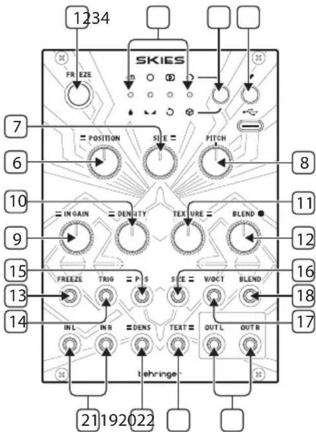
Controls
- FREEZE – use this button to freeze the contents of the recording buffer, and mute incoming audio. The surrounding LED will be lit when the buffer is frozen. Press again to unfreeze and unmute the inputs.
-
LEDs – the four LEDs have different functions according to the use of the FREEZE control 1, PARAMETER control 3, SAVE control 4 and GAIN control 9 and BLEND control 12:
-
When PARAMETER or SAVE is not being used they function as an audio input level meter, with the gain set by the GAIN control 9.
- When the FREEZE control has frozen the buffer they function as an audio output level meter.
- When the PARAMETER control is pressed quickly they indicate, by lighting in green, which mode the SKIES is in (see below).
- When the PARAMETER control is held for more than one second then pressed quickly they indicate, by lighting in red, the audio quality of the buffer (see below).
- When the value of the BLEND control is adjusted they light in sequence, and multiple colors, to indicate the blend value (see below).
-
When saving a buffer using the SAVE control one LED will blink to show which memory slot is being saved to (see below).
-
PARAMETER – use this button to select the function of the BLEND control 9; and to select the audio quality of the buffer. Press the button then press again to cycle through the options, indicated by the LED below the function lighting in green:
-
Wet/Dry balance
-
Stereo spread
-
Feedback amount
- Reverberation amount
Press and hold the button for more than one second then press again to cycle through the audio quality options, indicated by the LED above the option lighting in red:
- 32 kHz 16 bit stereo (1 second buffer size)
• 32 kHz 16 bit mono (2 second buffer size) - 16 kHz 8 bit stereo companded (4 second buffer size)
-
16 kHz 8 bit mono companded (8 second buffer size)
-
SAVE/LOAD – use this button to save the contents of the audio buffer, or to load a previously saved buffer. Press and hold the button for one second, then use the PARAMETER button 3 to select a memory slot to save to, which will be indicated by the relevant LED flashing in red. Press again to complete the save operation. Press the button for less than one second, then use the PARAMETER button to select a saved memory to load, which will be indicated by the relevant LED flashing in green. Press again to complete the load operation. The FREEZE button will activate and the audio buffer contents (if any) will be replaced by those saved to memory. Pressing FREEZE to de-activate removes the saved audio from the buffer.
If the button is pressed in error do not press any buttons for 10 seconds and the operation will not complete.
- USB – use this USB C socket to update the SKIES firmware using the SynthTribe app.
- POSITION – use this control to select the point in the buffer where the grains are generated from. The further clockwise (CW) the control is set the earlier in the buffer the process starts.
-
SIZE – use this control to set the size of the grains. Turning counter-clockwise (CCW) produces shorter grains, CW produces longer ones.
-
PITCH – use this control to adjust the pitch of the grains, relative to the recorded audio. At center there is no pitch alteration. Turning CCW reduces the pitch, CW raises it.
- INPUT GAIN – use this control to set the input gain to the buffer, from -18 dB fully CCW to +6 dB fully CW. The LEDs indicate the input level. If the last LED is lit then soft clipping will occur.
- DENSITY – use this control to adjust the grain density. At center no grains will be produced. Turning CCW produces regular grains with the amount produced increasing as the control is turned. Turning CW produces random grains, with the amount increasing the higher the control is set.
- TEXTURE – use this control to set the grain envelope and interaction. Positioning it fully CCW produces a square envelope, which morphs into a triangle then a smoothed Hann envelope. Once the control has passed 2 o'clock the grains start to smear into one another.
-
BLEND – use this control to set whichever parameter has been selected with the PARAMETER control 3 . The LED display will indicate the position of the control, from no LEDs lit at minimum, through green and yellow then red at maximum.
-
Wet/Dry balance – with the control fully CCW only the input audio will be heard, turning it CW blends in the grains from the buffer. At center they are evenly balanced. Fully CW and only the grains are heard.
- Stereo Spread – at center the grains will appear equally on both left and right outputs. Turning CCW biases them to the left; CCW to the right.
- Feedback amount – turning the control CW increases the amount of feedback, where grains are fed back into the buffer, producing a denser effect.
-
Reverberation amount – turning the control CW adds reverberation to the output.
-
FREEZE TRIGGER – use this 3.5 mm TS jack socket to trigger the FREEZE function from an external trigger.
- TRIGGER – use this 3.5 mm TS jack socket to trigger grain generation. When the DENSITY control is at center the external triggers take control of the SKIES for clocked generation.
- POSITION CV – use this 3.5 mm TS jack socket to control the POSITION function from an external CV source. Range is -8 V to +8 V.
- SIZE CV – use this 3.5 mm TS jack socket to control the SIZE function from an external CV source. Range is -8 V to +8 V.
- V/OCT – use this 3.5 mm TS jack socket to control the pitch of the SKIES from an external CV source. Range is 0 V to +8 V.
- BLEND CV – use this 3.5 mm TS jack socket to control the BLEND function from an external CV source. Range is -8 V to +8 V.
- DENSITY CV – use this 3.5 mm TS jack socket to control the DENSITY function from an external CV source. Range is -8 V to +8 V.
- TEXTURE CV – use this 3.5 mm TS jack socket to control the TEXTURE function from an external CV source. Range is -8 V to +8 V.
- INPUTS – use these 3.5 mm TS jack sockets to input audio into the buffer. If mono input is required use only the left socket.
- OUTPUTS – use these 3.5 mm TS jack sockets to output the mixed audio from the inputs and the grains produced, depending on the wet/dry control settings. If mono output is required use only the left socket. Care should be taken with the stereo spread settings when only one output is used.
ALTERNATIVE MODES
Aside from its main mode as a granular synthesizer/processor the Skies also has three alternative modes, which are accessed by pressing and holding the PARAMETER button 3 for five seconds. One of the four LEDs 2 will light up in red to show which mode is selected. A different mode can be selected by pressing the PARAMETER button to cycle through:
- Granular Synthesis/Processing (default)
- Pitch Shifting and Time Stretching
- Looping Delay
- Spectral Processing
PITCH SHIFTING AND TIME STRETCHING
When pitch shifting and time stretching is selected then the following controls functions change:
- DENSITY – creates a diffusion via the use of filters.
- TEXTURE – becomes a low pass/high pass filter.
- SIZE – controls the overlap of pitch shifted grains, from grainy glitches to loops.
- TRIG – sending a trigger to the TRIG input causes timed glitches, or, if FREEZE is also selected, synchronized loops.
LOOPING DELAY
In looping delay mode audio is played back from the buffer with no granular processing. The following controls functions change:
- POSITION sets the delay time. Use of POSITION CV or manual manipulation of the control creates an effect similar to scratching using vinyl records.
- FREEZE – creates a loop, with POSITION setting the loop start point and SIZE the loop length. DENSITY and TEXTURE work as they do in pitch shifting and time stretching mode. Sending a trigger to TRIG stutters the loop.
- Without FREEZE selected SIZE controls the way that pitch is shifted, from an almost ring modulated effect when fully counter-clockwise to a smooth effect as the control is turned clockwise. Sending a trigger to TRIG controls the delay time.
SPECTRAL PROCESSING
In spectral processing mode the following controls functions change:
- POSITION selects the buffer to which audio is sent when FREEZE is not selected. There are between two and seven buffers depending on the recording quality selected. If FREEZE is selected then POSITION selects the buffer which will be used for spectral synthesis.
- SIZE selects how the buffers interact, moving through spectral shifting to spectral reverse.
- PITCH controls the amount of pitch transposition involved in the shift.
- DENSITY affects how the buffers are re-synthesized.
- TEXTURE changes the quantization of the components from fully counter-clockwise to center; after which is increasingly amplifies weaker partials and attenuates stronger ones.
- Sending a trigger to TRIG causes the audio to glitch.
It goes without saying that spectral processing is difficult to describe in words and is best suited to free experimentation to see what happens.
CALIBRATION
Your SKIES will have been calibrated in the factory, but should it become necessary to re-calibrate it follow these steps:
- Disconnect all CV inputs, except V/OCT, which should be connected to a well calibrated keyboard.
- Press and hold the SAVE/LOAD button 4 and press the PARAMETER button 3. The first two LEDs will flash orange.
- Play C2 on your keyboard (1 V output).
- Press SAVE/LOAD again. All four LEDs will flash orange.
- Play C4 on your keyboard (3 V output).
- Press the SAVE/LOAD button. The SKIES will return to normal operation.
HINTS AND TIPS
- The Skies is a complex processor, and it is worth taking time to try different control settings to find what you want. Try the default user patch below as a starting point; and use the blank patch sheets to note effects that you like.
- Use a Behringer Radar contact microphone to trigger the creation of grains, and adjust parameters by CV
- When creating high density grains try randomly modulating at least one parameter to help the sound to develop.
- Be careful about using high feedback or reverberation settings when creating dense grains.
- Be careful about how you set wet/dry with the BLEND control. Because this control has many functions the position of its knob will not necessarily correspond to wet/dry. Too much dry and you will not get the benefit of your grains.
SKIES Default User Patch
EN
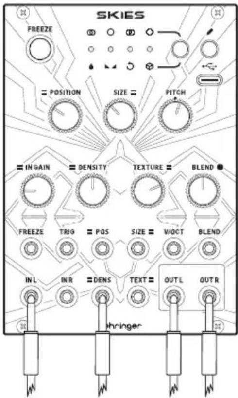
Wet/Dry is at center, as is stereo spread. Use an LFO to modulate Density.
Power Connection
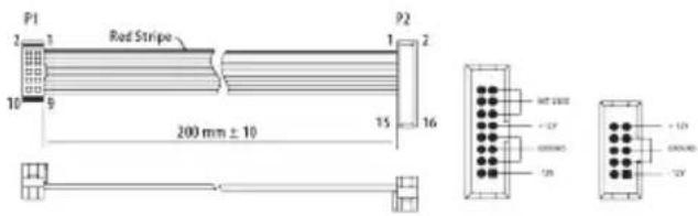
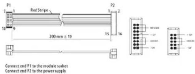
Connect end P1 to the module socket Connect end P2 to the power supply
The module comes with the required power cable for connecting to a standard Eurorack power supply system. Follow these steps to connect power to the module. It is easier to make these connections before the module has been mounted into a rack case.
- Turn the power supply or rack case power off and disconnect the power cable.
- Insert the 16-pin connector on the power cable into the socket on the power supply or rack case. The connector has a tab that will align with the gap in the socket, so it cannot be inserted incorrectly. If the power supply does not have a keyed socket, be sure to orient pin 1 (-12 V) with the red stripe on the cable.
- Insert the 10-pin connector into the socket on the back of the module. The connector has a tab that will align with the socket for correct orientation.
- After both ends of the power cable have been securely attached, you may mount the module in a case and turn on the power supply.
25Quick!
EN
Installation
The necessary screws are included with the module for mounting in a Eurorack case. Connect the power cable before mounting.
Depending on the rack case, there may be a series of fixed holes spaced 2 HP apart along the length of the case, or a track that allows individual threaded plates to slide along the length of the case. The free-moving threaded plates allow precise positioning of the module, but each plate should be positioned in the approximate relation to the mounting holes in your module before attaching the screws.
Hold the module against the Eurorack rails so that each of the mounting holes are aligned with a threaded rail or threaded plate. Attach the screws part way to start, which will allow small adjustments to the positioning while you get them all aligned. After the final position has been established, tighten the screws down.
GUÍA PARA PRINCIPIANTES SOBRE LA SÍNTESIS GRANULAR
Connect end P1 to the module socket Connect end P2 to the power supply
DE
Connect end P1 to the module socket Connect end P2 to the power supply
BEGINNERSGIDS VOOR GRANULAIRE SYNTHESIS
PITCH SHIFTING EN TIME STRETCHING
Connect end P1 to the module socket Connect end P2 to the power supply
- FREEZE – use this button to freeze the contents of the recording buffer, and mute incoming audio. The surrounding LED will be lit when the buffer is frozen. Press again to unfreeze and unmute the inputs.
-
LEDs – the four LEDs have different functions according to the use of the FREEZE control 1, PARAMETER control 3, SAVE control 4 and GAIN control 9 and BLEND control 12:
-
When PARAMETER or SAVE is not being used they function as an audio input level meter, with the gain set by the GAIN control 9.
- When the FREEZE control has frozen the buffer they function as an audio output level meter.
- When the PARAMETER control is pressed quickly they indicate, by lighting in green, which mode the SKIES is in (see below).
- When the PARAMETER control is held for more than one second then pressed quickly they indicate, by lighting in red, the audio quality of the buffer (see below).
- When the value of the BLEND control is adjusted they light in sequence, and multiple colors, to indicate the blend value (see below).
-
When saving a buffer using the SAVE control one LED will blink to show which memory slot is being saved to (see below).
-
PARAMETER – use this button to select the function of the BLEND control ⑨; and to select the audio quality of the buffer. Press the button then press again to cycle through the options, indicated by the LED below the function lighting in green:
-
Wet/Dry balance
-
Stereo spread
-
Feedback amount
- Reverberation amount
Press and hold the button for more than one second then press again to cycle through the audio quality options, indicated by the LED above the option lighting in red:
- 32 kHz 16 bit stereo (1 second buffer size)
• 32 kHz 16 bit mono (2 second buffer size)
• 16 kHz 8 bit stereo companded (4 second buffer size) -
16 kHz 8 bit mono companded (8 second buffer size)
-
SAVE/LOAD – use this button to save the contents of the audio buffer, or to load a previously saved buffer. Press and hold the button for one second, then use the PARAMETER button 3 to select a memory slot to save to, which will be indicated by the relevant LED flashing in red. Press again to complete the save operation. Press the button for less than one second, then use the PARAMETER button to select a saved memory to load, which will be indicated by the relevant LED flashing in green. Press again to complete the load operation. The FREEZE button will activate and the audio buffer contents (if any) will be replaced by those saved to memory. Pressing FREEZE to de-activate removes the saved audio from the buffer.
If the button is pressed in error do not press any buttons for 10 seconds and the operation will not complete.
- USB – use this USB C socket to update the SKIES firmware using the SynthTribe app.
- POSITION – use this control to select the point in the buffer where the grains are generated from. The further clockwise (CW) the control is set the earlier in the buffer the process starts.
-
SIZE – use this control to set the size of the grains. Turning counter-clockwise (CCW) produces shorter grains, CW produces longer ones.
-
PITCH – use this control to adjust the pitch of the grains, relative to the recorded audio. At center there is no pitch alteration. Turning CCW reduces the pitch, CW raises it.
- INPUT GAIN – use this control to set the input gain to the buffer, from -18 dB fully CCW to +6 dB fully CW. The LEDs indicate the input level. If the last LED is lit then soft clipping will occur.
- DENSITY – use this control to adjust the grain density. At center no grains will be produced. Turning CCW produces regular grains with the amount produced increasing as the control is turned. Turning CW produces random grains, with the amount increasing the higher the control is set.
- TEXTURE – use this control to set the grain envelope and interaction. Positioning it fully CCW produces a square envelope, which morphs into a triangle then a smoothed Hann envelope. Once the control has passed 2 o'clock the grains start to smear into one another.
-
BLEND – use this control to set whichever parameter has been selected with the PARAMETER control 3. The LED display will indicate the position of the control, from no LEDs lit at minimum, through green and yellow then red at maximum.
-
Wet/Dry balance – with the control fully CCW only the input audio will be heard, turning it CW blends in the grains from the buffer. At center they are evenly balanced. Fully CW and only the grains are heard.
- Stereo Spread – at center the grains will appear equally on both left and right outputs. Turning CCW biases them to the left; CCW to the right.
- Feedback amount – turning the control CW increases the amount of feedback, where grains are fed back into the buffer, producing a denser effect.
-
Reverberation amount – turning the control CW adds reverberation to the output.
-
FREEZE TRIGGER – use this 3.5 mm TS jack socket to trigger the FREEZE function from an external trigger.
- TRIGGER – use this 3.5 mm TS jack socket to trigger grain generation. When the DENSITY control is at center the external triggers take control of the SKIES for clocked generation.
- POSITION CV – use this 3.5 mm TS jack socket to control the POSITION function from an external CV source. Range is -8 V to +8 V.
- SIZE CV – use this 3.5 mm TS jack socket to control the SIZE function from an external CV source. Range is -8 V to +8 V.
- V/OCT – use this 3.5 mm TS jack socket to control the pitch of the SKIES from an external CV source. Range is 0 V to +8 V.
- BLEND CV – use this 3.5 mm TS jack socket to control the BLEND function from an external CV source. Range is -8 V to +8 V.
- DENSITY CV – use this 3.5 mm TS jack socket to control the DENSITY function from an external CV source. Range is -8 V to +8 V.
- TEXTURE CV – use this 3.5 mm TS jack socket to control the TEXTURE function from an external CV source. Range is -8 V to +8 V.
- INPUTS – use these 3.5 mm TS jack sockets to input audio into the buffer. If mono input is required use only the left socket.
- OUTPUTS – use these 3.5 mm TS jack sockets to output the mixed audio from the inputs and the grains produced, depending on the wet/dry control settings. If mono output is required use only the left socket. Care should be taken with the stereo spread settings when only one output is used.
ALTERNATIVE MODES
Aside from its main mode as a granular synthesizer/processor the Skies also has three alternative modes, which are accessed by pressing and holding the PARAMETER button 3 for five seconds. One of the four LEDs 2 will light up in red to show which mode is selected. A different mode can be selected by pressing the PARAMETER button to cycle through:
- Granular Synthesis/Processing (default)
- Pitch Shifting and Time Stretching
- Looping Delay
- Spectral Processing
PITCH SHIFTING AND TIME STRETCHING
When pitch shifting and time stretching is selected then the following controls functions change:
- DENSITY – creates a diffusion via the use of filters.
- TEXTURE – becomes a low pass/high pass filter.
- SIZE – controls the overlap of pitch shifted grains, from grainy glitches to loops.
- TRIG – sending a trigger to the TRIG input causes timed glitches, or, if FREEZE is also selected, synchronized loops.
LOOPING DELAY
In looping delay mode audio is played back from the buffer with no granular processing. The following controls functions change:
- POSITION sets the delay time. Use of POSITION CV or manual manipulation of the control creates an effect similar to scratching using vinyl records.
- FREEZE – creates a loop, with POSITION setting the loop start point and SIZE the loop length. DENSITY and TEXTURE work as they do in pitch shifting and time stretching mode. Sending a trigger to TRIG stutters the loop.
- Without FREEZE selected SIZE controls the way that pitch is shifted, from an almost ring modulated effect when fully counter-clockwise to a smooth effect as the control is turned clockwise. Sending a trigger to TRIG controls the delay time.
SPECTRAL PROCESSING
In spectral processing mode the following controls functions change:
- POSITION selects the buffer to which audio is sent when FREEZE is not selected. There are between two and seven buffers depending on the recording quality selected. If FREEZE is selected then POSITION selects the buffer which will be used for spectral synthesis.
- SIZE selects how the buffers interact, moving through spectral shifting to spectral reverse.
- PITCH controls the amount of pitch transposition involved in the shift.
- DENSITY affects how the buffers are re-synthesized.
- TEXTURE changes the quantization of the components from fully counter-clockwise to center; after which is increasingly amplifies weaker partials and attenuates stronger ones.
- Sending a trigger to TRIG causes the audio to glitch.
It goes without saying that spectral processing is difficult to describe in words and is best suited to free experimentation to see what happens.
CALIBRATION
Your SKIES will have been calibrated in the factory, but should it become necessary to re-calibrate it follow these steps:
- Disconnect all CV inputs, except V/OCT, which should be connected to a well calibrated keyboard.
- Press and hold the SAVE/LOAD button 4 and press the PARAMETER button 3. The first two LEDs will flash orange.
- Play C2 on your keyboard (1 V output).
- Press SAVE/LOAD again. All four LEDs will flash orange.
- Play C4 on your keyboard (3 V output).
- Press the SAVE/LOAD button. The SKIES will return to normal operation.
HINTS AND TIPS
- The Skies is a complex processor, and it is worth taking time to try different control settings to find what you want. Try the default user patch below as a starting point; and use the blank patch sheets to note effects that you like.
- Use a Behringer Radar contact microphone to trigger the creation of grains, and adjust parameters by CV
- When creating high density grains try randomly modulating at least one parameter to help the sound to develop.
- Be careful about using high feedback or reverberation settings when creating dense grains.
- Be careful about how you set wet/dry with the BLEND control. Because this control has many functions the position of its knob will not necessarily correspond to wet/dry. Too much dry and you will not get the benefit of your grains.
SKIES Default User Patch
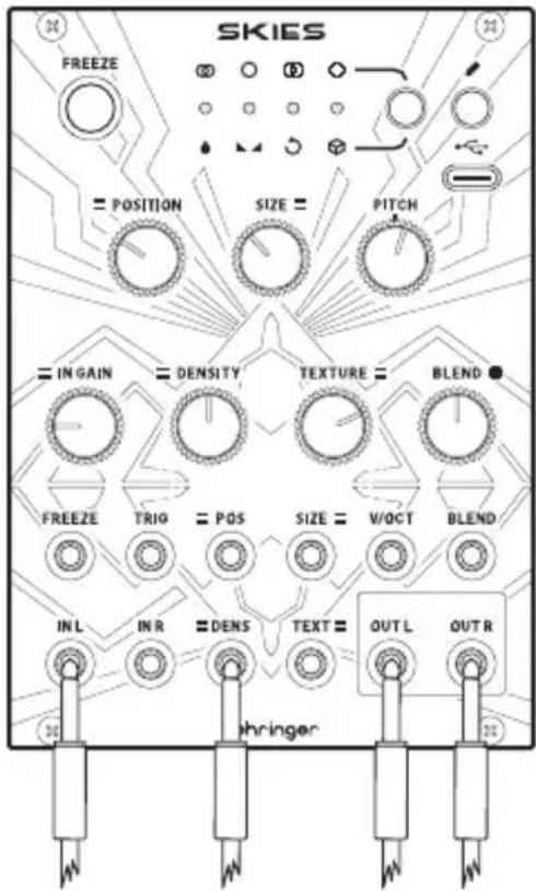
Wet/Dry is at center, as is stereo spread. Use an LFO to modulate Density.
Stroomaansluiting
The module comes with the required power cable for connecting to a standard Eurorack power supply system. Follow these steps to connect power to the module. It is easier to make these connections before the module has been mounted into a rack case.
- Turn the power supply or rack case power off and disconnect the power cable.
- Insert the 16-pin connector on the power cable into the socket on the power supply or rack case. The connector has a tab that will align with the gap in the socket, so it cannot be inserted incorrectly. If the power supply does not have a keyed socket, be sure to orient pin 1 (-12 V) with the red stripe on the cable.
- Insert the 10-pin connector into the socket on the back of the module. The connector has a tab that will align with the socket for correct orientation.
- After both ends of the power cable have been securely attached, you may mount the module in a case and turn on the power supply.
Installation
The necessary screws are included with the module for mounting in a Eurorack case. Connect the power cable before mounting.
Depending on the rack case, there may be a series of fixed holes spaced 2 HP apart along the length of the case, or a track that allows individual threaded plates to slide along the length of the case. The free-moving threaded plates allow precise positioning of the module, but each plate should be positioned in the approximate relation to the mounting holes in your module before attaching the screws.
Hold the module against the Eurorack rails so that each of the mounting holes are aligned with a threaded rail or threaded plate. Attach the screws part way to start, which will allow small adjustments to the positioning while you get them all aligned. After the final position has been established, tighten the screws down.
NYBÖRJARGUIDE TILL GRANULÄR SYNTES
PITCH SHIFTING OCH TIME STRETCHING
Connect end P1 to the module socket Connect end P2 to the power supply
Connect end P1 to the module socket Connect end P2 to the power supply
| USB Type C Socket | |
| Inputs | |
| Position CV | 3.5 mm TS jack, -8 V to + 8 V range, impedance 50 kΩ |
| Size CV | 3.5 mm TS jack, -8 V to + 8 V range, impedance 50 kΩ |
| V/Oct | 3.5 mm TS jack, 0 V to + 8 V range, impedance 50 kΩ |
| Blend CV | 3.5 mm TS jack, -8 V to + 8 V range, impedance 50 kΩ |
| Density CV | 3.5 mm TS jack, -8 V to + 8 V range, impedance 50 kΩ |
| Texture CV | 3.5 mm TS jack, -8 V to + 8 V range, impedance 50 kΩ |
| Freeze | 3.5 mm TS jack, 5 V peak to peak, impedance 50 kΩ |
| Trigger | 3.5 mm TS jack, 5 V peak to peak, impedance 50 kΩ |
| Audio Inputs left & right | 2 x 3.5 mm TS jack, AC coupled, impedance 22 kΩ |
| Outputs | |
| Audio Outputs left & right | 2 x 3.5 mm TS jack, AC coupled, impedance 1 kΩ |
| Controls | Position |
| Size | |
| Pitch | |
| Input Gain | |
| Density | |
| Texture | |
| Frequency | |
| Blend | |
EN
| Buttons | Freeze |
| Parameter | |
| Save/Load | |
| LEDs 4 x multi function | |
| Power Consumption | 120 mA (+12 V) / 10 mA (-12 V) |
| Physical | |
| Standard operating temperature | 5°C to 45°C (41°F to 113°F) |
| Dimensions | 128.5 x 91.12 x 55.7 mm(5.06 x 3.59 x 2.19") |
| Eurorack 18 hp | |
| Weight 187 g (6.6 oz) | |
Responsible Party Name: Music Tribe
Commercial NV Inc.
Address:
122 E. 42nd St.1,
8th Floor NY,
NY 10168,
United States
Email Address: legal@musictribe.com
SKIES
This equipment has been tested and found to comply with the limits for a Class B digital device, pursuant to part 15 of the FCC Rules. These limits are designed to provide reasonable protection against harmful interference in a residential installation. This equipment generates, uses and can radiate radio frequency energy and, if not installed and used in accordance with the instructions, may cause harmful interference to radio communications. However, there is no guarantee that interference will not occur in a particular installation. If this equipment does cause harmful interference to radio or television reception, which can be determined by turning the equipment off and on, the user is encouraged to try to correct the interference by one or more of the following measures:
- Reorient or relocate the receiving antenna.
- Increase the separation between the equipment and receiver.
- Connect the equipment into an outlet on a circuit different from that to which the receiver is connected.
- Consult the dealer or an experienced radio/TV technician for help.
EN
This equipment complies with Part 15 of the FCC rules. Operation is subject to the following two conditions:
(1) this device may not cause harmful interference, and
(2) this device must accept any interference received, including interference that may cause undesired operation.
Important information:
Changes or modifications to the equipment not expressly approved by Music Tribe can void the user's authority to use the equipment.
CE
Hereby, Music Tribe declares that this product is in compliance with General Product Safety Regulation (EU) 2023/988, Directive 2014/30/EU, Directive 2011/65/EU and Amendment 2015/863/EU, Directive 2012/19/EU, Regulation 519/2012 REACH SVHC and Directive 1907/2006/EC.
Full text of EU DoC is available at https://community.musictribe.com/
EU Representative: Empower Tribe Innovations DE GmbH Address: Otto-Brenner-Strasse 4a, 47877 Willich, Germany
UK Representative: Empower Tribe Innovations UK Ltd. Address: 5 Brindley Road Old Trafford, Manchester, United Kingdom, M16 9UN
We Hear You