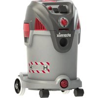
Energetic APDH-1430 - Vacuum Cleaner Starmix - Free user manual and instructions
Find the device manual for free Energetic APDH-1430 Starmix in PDF.


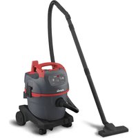
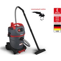
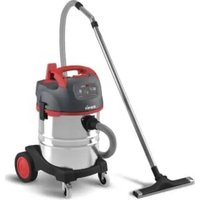
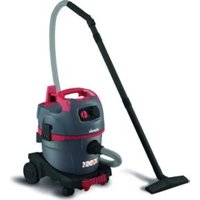
| Product type | Versatile industrial vacuum cleaner |
| Brand | Starmix |
| Model | Energetic APDH-1430 |
| Power supply | 220-240 V, 50-60 Hz, 1400 W |
| Max total power | 3600 W (tool socket included) |
| Tank capacity | 30 L |
| Max vacuum | 210 hPa |
| Max airflow | 70 L/s |
| Dust class | L (suction of non-flammable dry dusts, OEL > 1 mg/m³) |
| Sound level | 76 dB(A) at 1 m |
| Weight | 12.0 kg |
| Dimensions (L x W x H) | 405 x 375 x 612 mm |
| Protection rating | IPX4 (protection against water splashes) |
| Main functions | Dry and wet vacuuming, blowing, power tool connection (optional) |
| Included accessories | Crevice nozzle, upholstery brush, brush, floor nozzle (dry/wet), hose, tubes, filter bag |
| Filtration system | Cartridge filter FPP 3500 (class M) or HEPA H14 (class H) optional |
| Filter cleaning | Manual, semi-automatic or automatic (depending on version) |
| Thermal protection | Automatic shut-off in case of overheating (cooling 10 min) |
| Tank material | Plastic (30 L model) |
| Warranty | 2 years (parts and labor, excluding normal wear) |
Frequently Asked Questions - Energetic APDH-1430 Starmix
User questions about Energetic APDH-1430 Starmix
0 question about this device. Answer the ones you know or ask your own.
Ask a new question about this device
Download the instructions for your Vacuum Cleaner in PDF format for free! Find your manual Energetic APDH-1430 - Starmix and take your electronic device back in hand. On this page are published all the documents necessary for the use of your device. Energetic APDH-1430 by Starmix.
USER MANUAL Energetic APDH-1430 Starmix
natural_image
Exterior view of a gray starmix vacuum cleaner with red control knobs and wheels (no visible text or symbols on the device body)Bedienungsanleitung (original)
Operating instructions
en operating instructions....20
Abb. 4
natural_image
Line drawing of a vacuum cleaner with control panel and wheels (no text or symbols)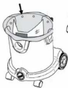
natural_image
Line drawing of a vacuum cleaner with mounting feet and a handle (no text or symbols)Abb. 6B
natural_image
Technical line drawing of a mechanical device with no visible text or symbolsAbb. 6A
4.2 TROCKEN- ODER NASSBODENABSAUGUNG
natural_image
Line drawing of a car air purifier with labeled component (no text or symbols)Abb. 13
natural_image
Line drawing of a vacuum cleaner with a bag and handle, alongside a separate sketch of a bag with a handle (no text or symbols)Abb. 14
4.10 EINSTELLEN DES
SCHLAUCHDURCHMESSERS (OPTIONAL)
flowchart
graph TD
    A["Implant with internal components"] --> B["Cut into a cup"]
    B --> C["Sputum with sutured part"]
Abb. 16
5 FILTERREINIGUNG
Abb. 17
5.2 HALBAUTOMATISCHE FILTERREINIGUNG (OPTIONAL)
natural_image
Line drawing of a mechanical device with wheels and internal compartments (no text or symbols)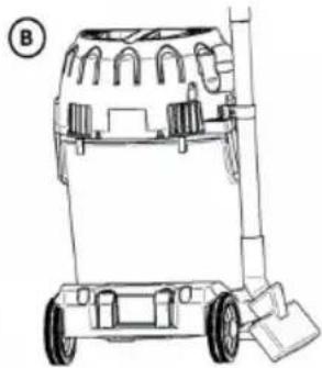
natural_image
Line drawing of a wheeled cart with wheels and a handle, no text or symbols presentAbb. 20
natural_image
Technical line drawing of a mechanical component with no visible text or symbolsAbb. 21
natural_image
Line drawing of a compact vacuum cleaner with wheels and control knobs (no text or symbols)Abb. 23
natural_image
Line drawing of a vacuum cleaner with labeled component A (no text or symbols beyond label)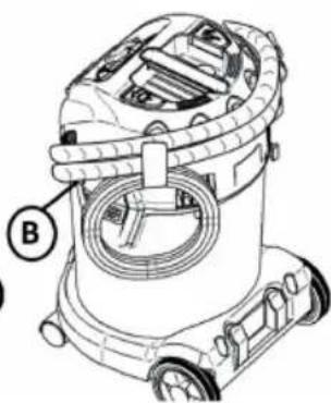
natural_image
Technical line drawing of a vacuum cleaner with labeled component B (no text or symbols beyond label)Abb. 22
▶ Danger of suffocation
- Keep packaging material such as plastic bags away from children.
▶ Never stand or sit upon the vacuum device.
▶ Particular caution is advised when ascending stairs. Pay attention to standing safely.
- Do not pull the suction hose and connection line over sharp edges, kink it or shut it.
▶ Always lay the suction hose and connection line so that nobody may trip over them.
In case of any leakage of foam or liquid, immediately switch off the vacuum device.
▶ Always keep dry the inside of the lid.
▶ Do not start the vacuum device including its accessories if:
• the vacuum device shows detectable damage (fissures/cracks);
- the power connection line is defective or shows fissuring or ageing; or
• any invisible defect is suspected (after a fall)..
⚠️ DANGER!
▶ Do not operate the vacuum device where there is danger of explosions.
- Keep away the vacuum device from inflammable gases and substances.
DANGER!
- Do not aspirate any combustible or explosive solvents, materials soaked in solvents, explosive dusts, liquids such as petrol, oil, alcohol, diluents or materials hotter then 60 °C (140 °F).
Otherwise there will be danger of fire and explosions!
DANGER!
- Have repairs been made only by experts, e. g. the producer's service. Use original spare parts only.
▶ Improperly repaired devices pose a hazard for the user.
⚠️ DANGER!
▶ Use the socket of the vacuum device only for the purposes defined in the instruction manual.
In case of any inappropriate usage, improper operation or repair, the producer shall be exempt from liability.
▶ Do not use any damaged extension lines.
If the connector line of the vacuum device has been damaged, it must be replaced with a special connector line which is available from the producer or their service.
▶ The voltage on the type sign must correspond to the grid voltage.
▶ After every use and before any maintenance, switch off the vacuum device and pull the power plug.
▶ Pull on the plug only, not on the line.
▶ Never plug or pull the power plug with wet hands.
The socket must be secured via a household fuse with a suitable current rating.
▶ Never open the vacuum device outdoors in rain or storm.
▶ Store the vacuum cleaner dry and indoors, protected from frost.
⚠ WARNING!
▶ Vacuum devices are not suitable for aspiration/clearing of toxic dusts.
- Vacuum cleaner for dust class L suitable for up / exhausting of dry, non-flammable, hazardous dust with occupational exposure limit values (AGWS) > 1 mg/m³.
Class M vacuum devices are suitable for aspiration/clearing of dry, non-combustible dusts, non-combustible liquids, wood dusts and hazardous dusts with workplace limit values of ≥ 0.1 mg/m ^3 .
Class H vacuum devices are suitable for aspiration/clearing of dry, non-combustible dusts, carcinogenic and pathogenic particles as well as non-combustible liquids, wood dusts and toxic dusts with all workplace limit values.
⚠ WARNING!
The machine may not be used by persons (including children) who have reduced physical, sensory or metal capabilities or who are inexperienced or lack the knowledge of how to use the machine.
▶ Children must be supervised to ensure that they do not play with the device.
▶ Do not point nozzle, tube or hose at people or animals.
⚠ WARNING!
▶ Only use the accessories provided with the vacuum cleaner or those specified in the instruction manual. The use of other accessories may compromise safety.
- Clean and disinfect the vacuum device immediately after use to prevent microbial contamination due to long-term failure to clean it, especially when using the device in food-processing.
▶ Do not use any steam jets or high-pressure cleaners for cleaning.
▶ Acids, acetone and solvents may corrode parts of the vacuum device.
- Do not leave the device without supervision. In case of longer interruptions of work, pull the power plug.
- Do not clean filter cassettes with compressed air.
Read the operating manual carefully before starting to use the vacuum cleaner. It provides important instructions for the operation, safety, care and maintenance. Keep the operating manual in a safe place and, in case you sell the unit, hand it on to the next owner.
The manufacturer reserves the right to carry out modifications to the design and equipment.
Any other work not covered by this operating manual must not be carried out.
This machine is intended for commercial use, for example, in hotels, schools, hospitals, factories, shops, offices and in the rental business.
Before use
- When unpacking, check that the delivery is complete and that there is no transport damage.
Before using, the operators should be provided with information, instructions and training for the use of the vacuum cleaner and the substances that it is to be used for, including the safe procedure for the removal of the gathered material.
1 IMPORTANT SAFETY INSTRUCTIONS
- Warning and information plates on the machine provide important directions for safe operation.
- Apart from the notes contained herein the general safety provisions and rules for the prevention of accidents of the legislator must be observed.
1.1 SYMBOLS USED ON THE MACHINE
WARNING
For Dust Class H machines following applies: The appliance is suitable for picking up dry, nonflammable dust, non flammable
liquids, hazardous dusts with OEL (Occupational Exposure Limit) values, carcinogenic dusts, dusts containing germs.
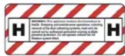
Dust Class H (IEC 60335-2-69). The dusts which belong to this class are: dusts with OEL values (Occupational Exposure Limit), all carcinogenic dusts and dusts which are mixed with pathogenic agents. Vacuums for Dust Class H are tested in their entirety and have a maximum degree of permeability of 0.005%. The disposal must be dust free
The safety label on the machine warns: This appliance contains dust hazardous to health. Emptying and maintenance operations, including removal of the dust collecting means, must only be carried out by authorised personnel wearing suitable personal protection. Operate only after the full fi ltration system has been fitted and checked
The Dust Class M version contains hazardous dust. Emptying and maintenance, including the removal of the dust bag, may only be carried out by someone who is familiar with the unit and wearing suitable protective gear. Do not switch on the unit until the complete filter system has been installed and the function of the volume-fl ow control has been tested.

• Note: You can use this appliance to take up all types of dust up to dust class M. It is statutorily necessary to use a dust collection bag.
- Note: The appliance is suited as industrial vacuum cleaner and as dedusting device for the mobile operation to take up dry, noncombustible dusts with AGW values greater than or equal to 0.1mg / m^3 .
- When vacuuming up fi ne dust, an additional fl eece fi iter bag or a dust bag must additionally be used
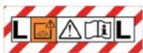
This Dust Class L version suitable for the following applications:
- A Dust Class L appliance is suitable for picking up dry, non-fl ammable dusts, liquids, wood chips and hazardous dusts with an exposure limit value of >1mg/ m^3 . The appliance must be equipped with a suitable fi Iter corresponding to the hazard classification of the dusts to be picked up.
- Pick up only hazardous substances in accordance with IEC/EN 60335-2-69 (class L) with the appropriate vacuum cleaner. Use for picking up other hazardous substances is prohibited.
1.2 HAZARDS LEVELS
DANGER
Pointer to immediate danger, which leads to severe injuries or death.
WARNING
Pointer to a possible dangerous situation, which can lead to severe injuries or death.
CAUTION
Pointer to a possible dangerous situation, which can lead to minor injuries.
1.3 SAFETY INSTRUCTIONS
DANGER
- When the outgoing air is carried back into the room, a sufficient ventilation rate L in the room must be ensured. To comply with the required limit values the carried back volume flow must be 50% of the fresh air volume flow (room volume VR x ventilation rate LW) at maximum. Without a specific ventilation system the following applies: LW=1h-1.
- Only persons trained in the use of the machine and the handling of substances for which the machine is to be used including training in the safe disposal of the sucked-in material may use the machine.
• This appliance can contain harmful dust. Evacuation and maintenance work, including the disposal of the dust collection containers, may only be performed by specialists who wear the appropriate protective equipment. - Do not use the appliance without the complete filtering system.
- Please follow the safety regulations applicable to the materials that are to be sucked up.
1.4 1.4 POWER CORD
DANGER
- The voltage indicated on the type plate must correspond to the voltage of the electrical source.
- Please use the mains cable prescribed by the manufacturer; the same is also applicable when you replace the cables.
- Check the power cord with mains plug for damage before every use. If the power cord is damaged, have it replaced immediately by the authorised customer service/electrician in order to avoid possible hazards.
- The appliance may only be connected to an electrical supply which has been installed by an electrician in accordance with IEC 60364.
- Never touch the mains with wet hands.
- Make sure that the power cord or extension cables are not damaged by running over, pinching, dragging or similar. Protect the cable from heat, oil, and sharp edges.
- The power cord must be checked regularly for damages, such as cracks or aging. If damage is found, the cable must be replaced before further use.
- If couplings of the power cord or extension cable are replaced the splash protection and the mechanical tightness must be ensured.
- Do not clean the appliance with a water hose or high pressure water jet (danger of short circuits or other damage).
1.5 APPLICATION
DANGER
- Appliances with working equipment, specifically the power cord and the extension cable, must be checked to ensure that it is in proper working order and is operating safely prior to use. Otherwise, immediately pull out the power plug. The appliance must not be used.
- Do not vacuum up any burning or glowing objects.
- Humans and animals must not be vacuumed with this appliance.
-
Appliances may not be used in outside areas in low temperatures.
-
It is not allowed to use the appliance in hazardous locations.
- Certain materials may produce explosive vapours or mixtures when agitated by the suction air!
- CAUTION This machine shall be stored indoors only
- CAUTION This machine may only be stored indoors
- Never vacuum up the following materials:
o Explosive or combustible gases, liquids and dust particles (reactive dust particles)
o Reactive metal dust particles (such as aluminium, magnesium, zinc) in combination with highly alkaline or acidic detergents
o Undiluted, strong acids and alkalies
o Organic solvents (such as petrol, paint thinners, acetone, heating oil).
In addition, these substances may cause the appliance materials to corrode.
1.6 OPERATION
DANGER
- The operator must use the appliance properly. The person must consider the local conditions and must pay attention to third parties, in particular children, when working with the appliance.
- Never leave the appliance unattended as long as it is in operation and the power cord has not been pulled.
• Always use appropriate gloves while working with the device. - The appliance may only be used by persons who have been instructed in handling the appliance or have proven qualification and expertise in operating the appliance or have been explicitly assigned the task of handling the appliance.
- This appliance is not intended for use by persons (including children) with reduced physical, sensory or mental capabilities, or lack of experience and knowledge, unless they have been given supervision or instruction concerning use of the appliance by a person responsible for their safety.
- Children should be supervised to prevent them from playing with the appliance.
WARNING
- The appliance is not suitable for vacuuming dust which endangers health.
- Do not allow the supply cord to come into contact with the rotating brushes.
- Operators shall be adequately instructed on the use of these machines.
- Before use, operators shall be provided with information, instruction and training for the use of the machine and the substances for which it is to be used, including the safe method of removal and disposal of the material collected
1.7 TRANSPORT
WARNING
- The motor is to be brought to a standstill and the appliance is to be fastened properly during transportation.
CAUTION
- In order to prevent accidents or injuries, mind the weight of the appliance during transport (see technical data).
1.8 MAINTENANCE
DANGER
- Switch off the appliance and, in case of appliances connected to the mains, pull out the power cord before cleaning and performing any maintenance tasks on the machine.
- Dust extracting machines are safeguards for the prevention or elimination of hazards defined in the regulations of BGV A1 (Germany only).
-
In order to carry out maintenance work, the user must disassemble, clean and service the unit, in so far as this is possible without endangering maintenance personnel and other persons. Suitable precautions include decontamination before the unit is disassembled. Precautions must be taken for local filtered forced air ventilation at the place where the unit is disassembled, the cleaning of the maintenance surface and suitable protection of the personnel.
-
The outside of the unit should be cleaned thoroughly and any harmful substances removed. Alternatively, a sealed coating may be applied before the unit is removed from the danger area. All unit parts are to be considered contaminated when they are removed from the danger area. To avoid distribution of the dust, you must take the appropriate measures.
- In the framework of maintenance and repair work all contaminated objects that cannot be cleaned satisfactorily must be disposed of. Such objects must be disposed of in impermeable bags in accordance with the valid provisions for the disposal of such waste.
- When transporting or maintaining the device, the suction opening must be closed with the plug.
- Maintenance work may only be carried out by approved customer service outlets or experts in this field who are familiar with the respective safety regulations.
- Please observe the local safety regulations regarding portable commercially used appliances.
- Risk due to dust hazardous to health. Always use disposal clothing and P2 or higher breath-safe masks while carrying out maintenance tasks (such as changing filters).
- For class H and class M machines, the outside of the machine should be decontaminated by vacuum cleaning methods and wiped clean or treated with sealant before being taken out of a hazardous area. All the machine parts shall be regarded as contaminated when removed from the hazardous area and appropriate action taken to prevent dust dispersal
- You can test the servifiltration capacity of the device using the test procedure specified in EN 60 335–2–69 22.AA.201.2. This test must be done at least once a year or more frequently if the national regulations demand it. If the test results are negative, the test is to be repeated with a new cartridge filter.
ATTENTION
Risk of damage! Do not use detergents containing silicone to clean.
- No outside help is required for carrying out basic maintenance and cleaning.
- The appliance surface and the inside of the container should be cleaned regularly using a damp cloth.
1.9 SAFETY DEVICES
CAUTION
- Safety installations serve the protection of the user and may not be modified or bypassed.
WARNING
- Safety equipment for preventing hazards must be serviced and maintained regularly. This means that the manufacturer's staff or persons trained by the manufacturer must check the equipment for proper functioning at least once a year, i.e. check for leaks, filter damage, functioning of the controlling elements, etc.
Warning light and sound
- Warning light and/or warning sound will go on when the air speed in hose falls below 20 m/s for Dust Class M and H version.
1.10 Tests and approvals
Electrical tests must be performed in accordance with the provisions of safety regulations EN 62638. These tests must be performed at regular intervals and after repairs or modifications. The vacuum cleaner has been approved in accordance with IEC/EN 60335-2-69.
2 OVERVIEW
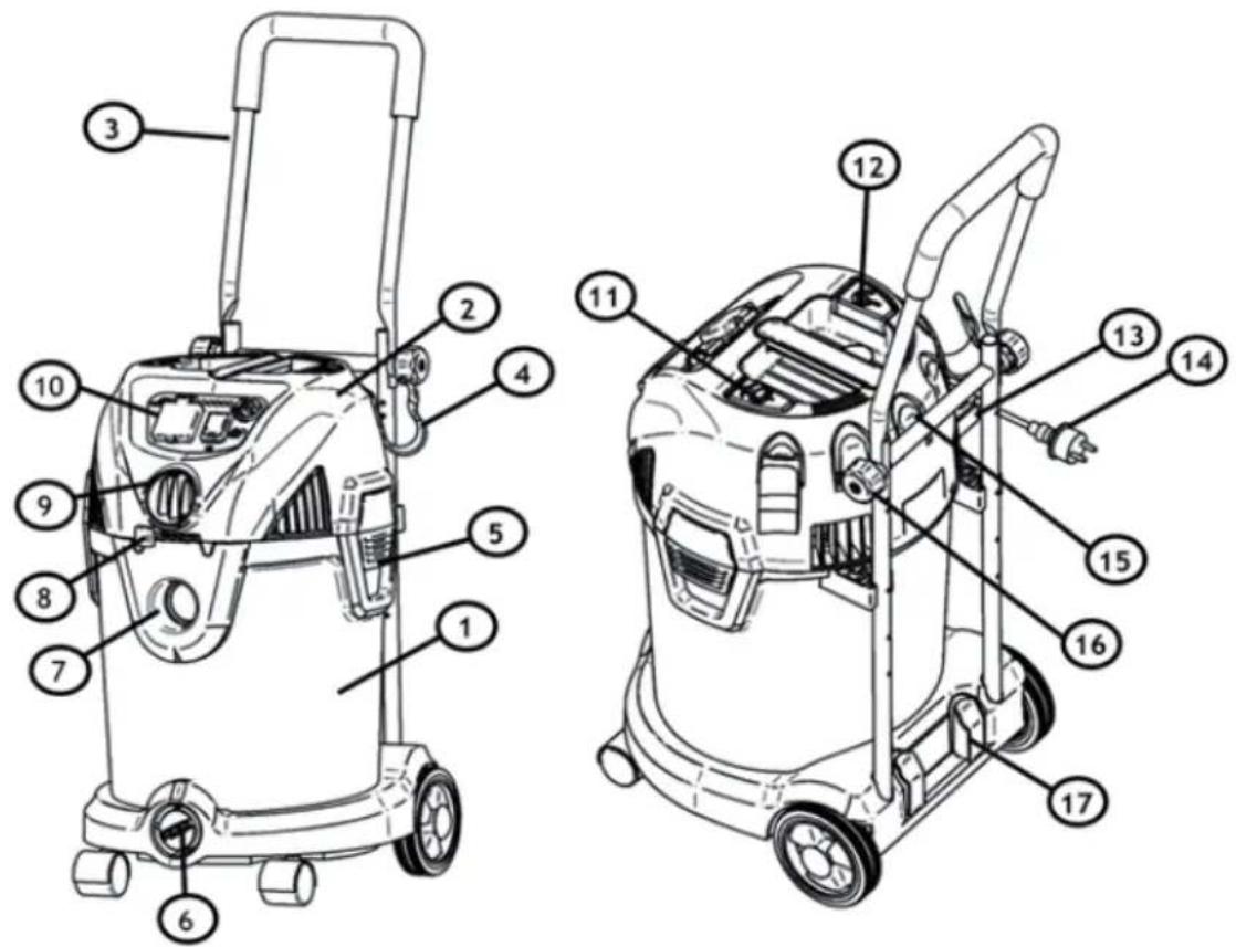
| 1. Tank 11. Filter Cleaning Button (optional) | |
| 2. Head 12. Cord rewind button (optional) | |
| 3. Trololey (optional) 13. Parking hook receptable | |
| 4. Hose and cord storage hook (optional) 14. Cord Plug | |
| 5. Clamp 15. Nozzle storage holders | |
| 6. Drain outlet 16. Trolley lock screw | |
| 7. Suction inlet 17. Tube storage holders | |
| 8. Blow regulation (only Dust class L machines) | |
| 9. Blow outlet or hose size adjustment | Some of these accessories are packed inside the tank. If parts are missing, contact our Customer Service Dep |
| 10. control panel | 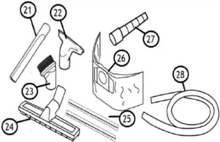 |
| 21. Crevice Nozzle | |
| 22. Upholstery nozzle | |
| 23. Brush nozzle | |
| 24. Floor nozzle (dry pickup) | |
| 25. Scraper insert (wet pickup) | |
| 26. Dust bag | |
| 27. Power tool adapter (optional) | |
| 28. Suction hose |
3 FIRST TIME SET UP INSTRUCTIONS
Read chapter 1 – IMPORTANT SAFETY INSTRUCTIONS of this manual thoroughly before setting up and using this vacuum cleaner
3.1 ACCESSORIES
The nozzles and accessoires for the machine is during shipping stored in tank. To open the tank open the clamps and take off the head. Take out the items and put on the head again. Secure the head with the clamps.
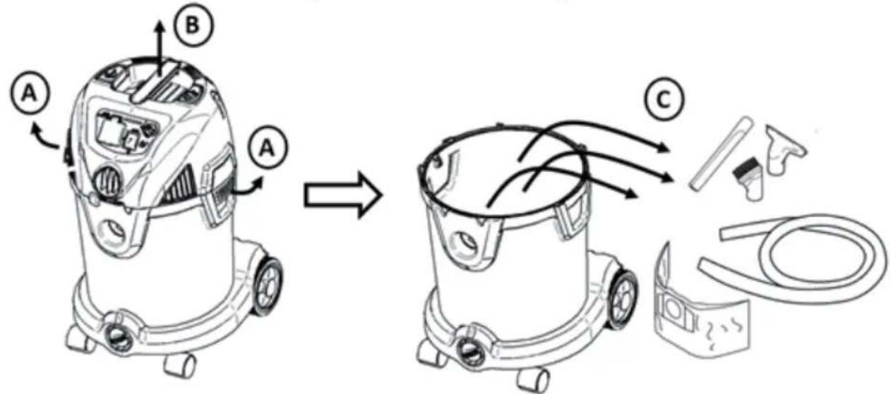
Fig. 3
See chapter 6 where to store the accessories on the machine.
3.2 MOUTING OF HOSE AND CORD HOLDER
Add the two hose/cord holders in the appropriate receptable on the head
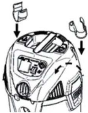
Fig. 4
3.3 PREPARING THE TROLLEY (OPTIONAL)
The trolley can be folded during transpotation. To fi x it in the upright position swing the top trolley part up (A) and fi x it with the 2 screws (B). Make sure to tighten both sides equal
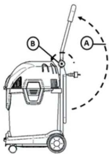
Fig. 5
4 USING THE VACUUM CLEANER
4.1 WORKING WITH DUST BAGS
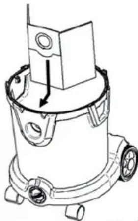
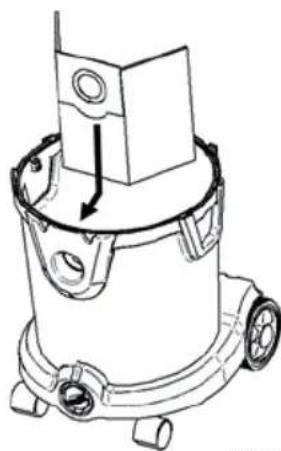
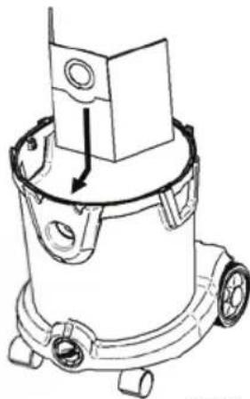
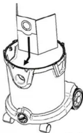
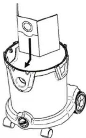
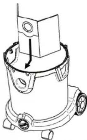
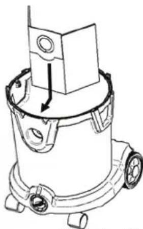
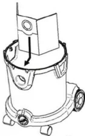
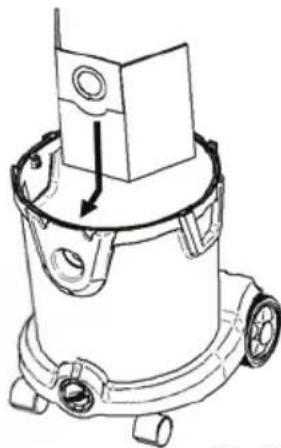
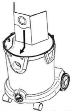
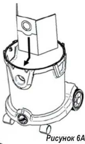
If sucking up dry dust an optional dust bag can be used to collect the dust and ease the disposal. To insert the dust bag take off the head (see also figure 3). Insert the dustbag like shown on figure 6A. Put on the head again and secure the head with the clamps
Fig. 6A
For Dust Class M dustless emptying is required and thus a Dust bag or similar should be used
natural_image
Technical line drawing of a mechanical device with no visible text or symbolsFig. 6A
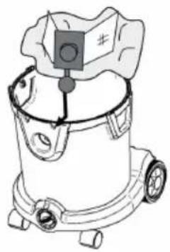
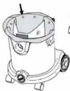
For Dust Class H machine dust free emptying is required. Use the special safety dust bag as on fi gure 6b. Fit the plastic fi tting part of the dust bag onto the fi tting inside the tank. Make sure it is properly fi xed. Wrap the plastic bag over the edge of the tank. Make sure the hole to equalized the pres sure are located inside the tank
natural_image
Line drawing of a vacuum cleaner with control panel and wheels (no text or symbols)
natural_image
Technical line drawing of a mechanical device with no visible text or symbolsFig. 6B
4.2 DRY OR WET FLOOR SUCTION
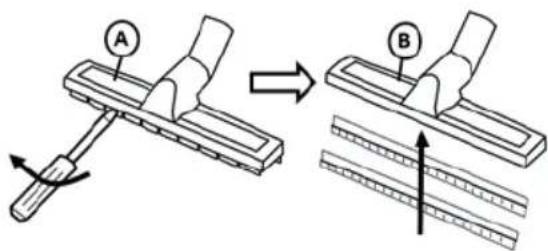
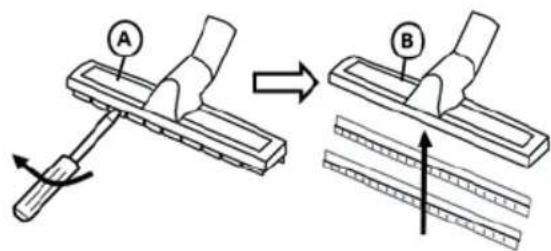
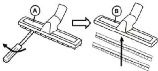
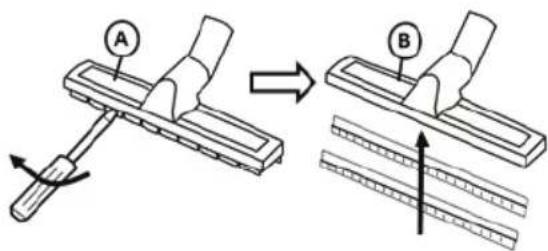
To suck up dry dust and debris use the dry floor nozzle (A) with the bristles rim.
To suck up wet debris replace the brush rim with a screwdriver and insert the rubber squeegees
Fig. 7
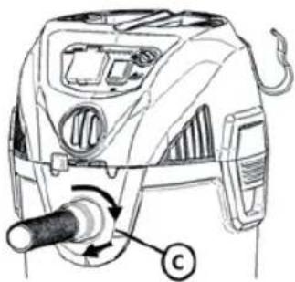
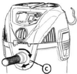
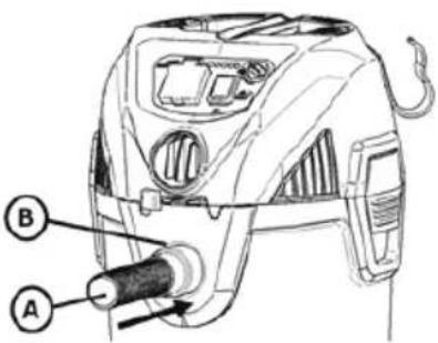
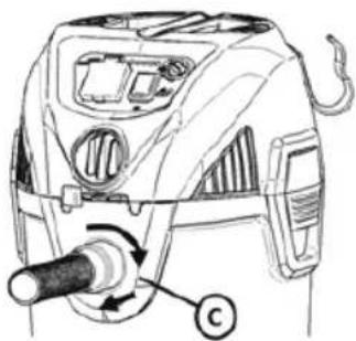
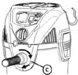
4.3 VACUMING - INSERTING AND REMOVING THE HOSE
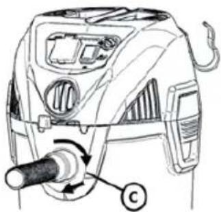
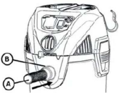
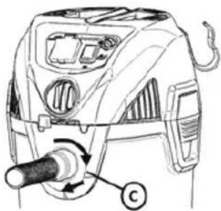
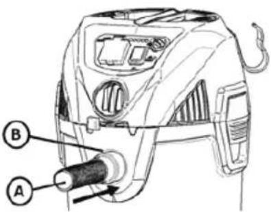
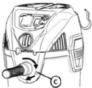
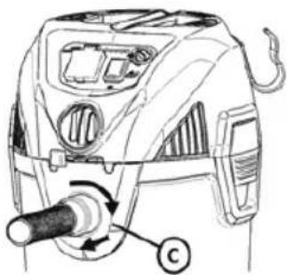
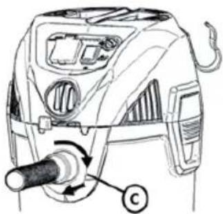
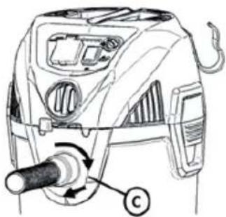
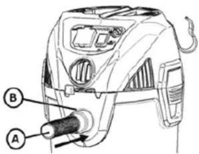
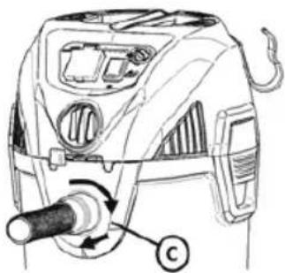
To vacuum insert the hose (A) into the suction inlet (B).
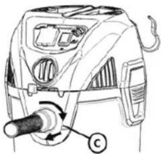
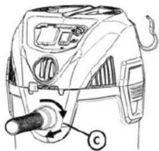
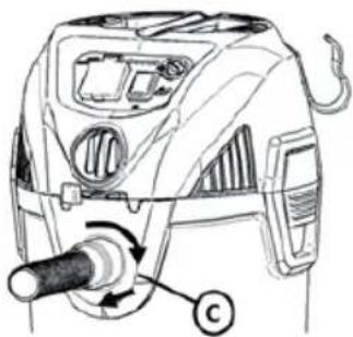
To remove the hose twist and pull in one movement to remove (C)
Fig. 8
natural_image
Technical line drawing of a mechanical device with labeled component (no text or symbols)4.4 BLOWING (ONLY DUST CLASS L) - INSERTING AND REMOVING THE HOSE
The machine can also be used for blowing.
To use the blow function insert the hose into the blow outlet (A) in the same way for the suction inlet. See above. The blowing can be controlled by the lever (B)
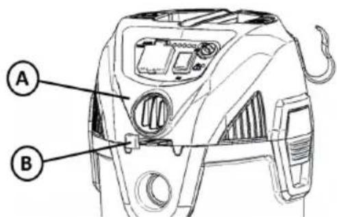
Fig. 9
4.5 TURNING THE MACHINE ON
The machine is turned on/off by pressing the start/ stop button (A). The machine can optionally be equipped with LEDs with power control (C). By turning the knob the suction of the machine can be controlled. The suction performance is also shown by the LEDs. If equipped with LED the 1st LED from left, when the machine is plugged in, will be ON.
To use the optional socket (B) see next chapter.
The machine can optionally be configured with an indicator (D). The indicator goes on, when the underpressure is high. This can be due to the filter being clogged and needs to be cleaned (see later chapter) or the bag/tank is full and need to be replaced/emptied
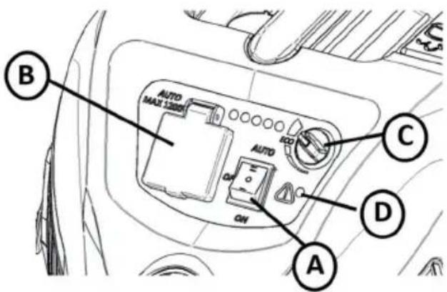
Fig. 10
4.6 MACHINE WITH SOCKET AND AUTO START/STOP (OPTIONAL)
The machine can optionally be equipped with a socket that can be used in connecting with a power tool. Connect the power tool to the socket (A). Remove the handtube and fix the conical adapter (B). Insert the conical adapter to the power tool (C). Turn the machine to AUTO mode with the switch (D). The machine will then start, when the power tool is turned on and stop with a delay (in order to empty the hose) when the power tool is turned off
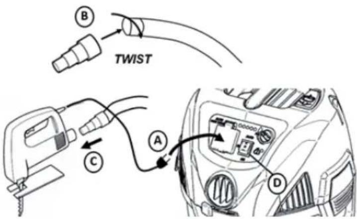
Fig. 11
! WARNING - Do not operate without filter basket and float, as they prevent liquid from entering the impeller and damaging the motor. Do not suck up any liquids without a sponge filter installed.
! WARNING - Only use the socket on the machine for the purposes specified in the instructions..
NOTE: IF ACCIDENTALLY TIPPED OVER, THE VACUUM COULD LOSE SUCTION. IF THIS OCCURS, PLACE VAC IN UPRIGHT POSITION AND TURN SWITCH OFF. THIS WILL ALLOW THE FLOAT TO RETURN TO ITS NORMAL POSITION, AND YOU WILL BE ABLE TO CONTINUE OPERATION.
! WARNING - Read the Safety Warnings and Instructions concerning the types of wet materials that cannot be vacuumed with this product.
! DANGER - This equipment incorporates parts such as switches, motors or the like that tend to produce arcs or sparks that can cause an explosion. Do not pick up flammable, combustible, or hot materials. Do not use around explosive liquids or vapors, as electrical devices produce arcs or sparks which can cause a fire or explosion.
This vacuum cleaner has a built in thermal overload protector to protect the motor from high temperatures. This can occur under heavy use. If the motor temperature shuts off during operation, turn the switch off and allow the motor to cool for 10 minutes. Turn switch on and resume operation.
4.7 EMPTYING THE TANK FOR LIQUID
To empty the tank for liquid unscrew the drain plug (A) and remove it.
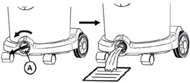
Fig. 12
4.8 EMPTYING THE TANK FOR DUST/DEBRIS FOR DUST CLASS L MACHINES)
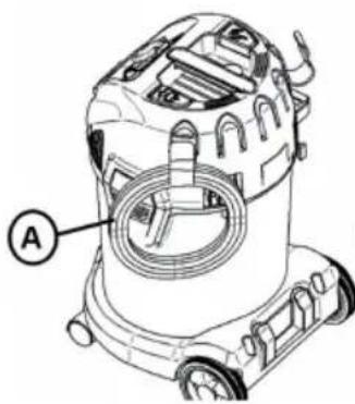
To empty the tank for dust/debris take off the head (see chapter 3.1). If using a dust bag remove the dust bag and insert a new. Machines with 20l and 30l plastic tanks can optional be equipped with a handle (A) that can be using during disposal of the dust/debris.
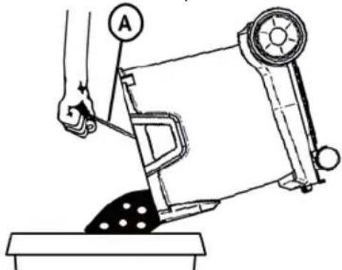
natural_image
Line drawing of a hand operating a machine with a labeled component (no text or symbols present)Fig. 13
4.9 CHANGING OF THE SAFETY DUST BAG FOR DUST CLASS H MACHINES
DANGER
The dust that has been collected should be transported in dust-proof containers. No refi lling
is permitted. The waste containing hazardous dust is to be disposed off according to the rules and regulations for waste disposal
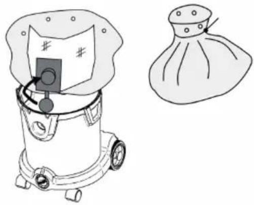
Fig. 14
Only persons trained in waste disposal are permitted to dispose off the dust collection container.
Release the plastic fl ange from the inlet in the tank. Close the inlet on the safety dust bag with the lid as on on Fig. 14. Wrap the plastic bag around the filter bag and close it with the cable tie fixed to the bag
natural_image
Line drawing of a vacuum cleaner with a bag and a separate close-up of its cap (no text or symbols)4.10 ADJUSTING THE SIZE OF THE HOSE (OPTIONAL)
For M-Class and H-Class it is necessary to adjust the size of the hose to fit the hose attached to the machine. This can be done with the button (A) on Fig. 15.
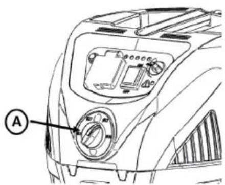
Fig. 15
4.11 CHANGING FILTER FOR DUST CLASS H MACHINE
WARNING
The dust that has been collected should be transported in dust-proof containers. No refi lling is permitted. The waste containing hazardous dust is to be disposed off according to the rules and regulations for waste disposal.
Do not reuse the main filter element after it has been removed from the appliance
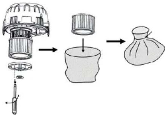
Remove the fi lter disc fi rst with a screw driver as on Fig. 16 and then twist to remove. Take out the the cartridge fi lter. On removing the cartridge fi lter, cover the same immediately with an enclosed bag and close it. Dispose off the used cartridge fi lter in a dust-tight bag according to the statutory provisions.
Remove the dirt that has accumulated on the pure air side. Insert new cartridge filter. During placement, make sure that the cartridge filter rests against all sides. Insert filter discs and fix it with screw.
flowchart
graph TD
    A["Implant with internal components"] --> B["Sash Bag"]
    B --> C["Assembly of a sash bag into a cup and part of the sash bag"]
    style A fill:#f9f,stroke:#333
    style B fill:#ccf,stroke:#333
    style C fill:#cfc,stroke:#333
Fig. 16
5 Filter Cleaning
The machine can optionally be equipped with a semi automatic filter cleaning system or fully automatic filter cleaning system
5.1 MANUAL FILTER CLEANING (ONLY FOR DUST CLASS L AND M)
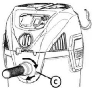
When sucking fine dust the filter will eventually get clogged and suction will go down. The filter therefore needs to be cleaned to restore suction. If the machine is not equipped with semi- or fully automatic filter cleaning system (see next chapters), the filter can be cleaned in the following manual way. Turn the knob (A) and remove the knob from the filter disc (B). Remove the filter (C). Clean the filter under cold water (D). Let is dry (E) until completely dry. Install backwards by adding filter (F). Fixing the filter disc (G) and securing it with the knob (H).
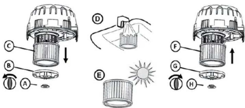
Fig. 17
5.2 SEMI AUTOMATIC FILTER CLEANING (OPTIONAL)
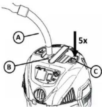
When the machine is equipped with the semi automatic fi liter cleaning system, the fi liter can be cleaned by closing the inlet of the handtube (A). However, fi rst turn the machine to max. power if equipped with power control (see figure 10). Close the inlet which can be done with your hand or the receptable/hole in the machine (B) can be used. After closing the inlet wait 2-3 seconds until the maximum underpressure has been built up. Press the fi liter cleaning button (C) 5 times fast after each other. This action will clean the fi liter and restore suction performance
Fig. 18
5.3 FULLY AUTOMATIC FILTER CLEANING (OPTIONAL)
The fully automatic fi liter cleaning system cleans the fi liter automatically approx. every 15 seconds. The fi liter cleaning takes less than a second and a very little interruption of the suction performance takes place during the fi liter cleaning. A small "bang" can be heard. The automatic fi liter cleaning system works best, when the underpressure in the machine is high. If fi liter for some reason should be clogged and suction is low then turn the machine to max. power (if confi gured with power controller) then close the inlet of the machine and wait until a small "bang" can be heard. The fi liter will then be cleaned and suction restored
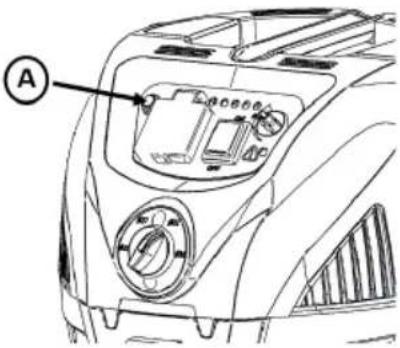
Fig. 19
The automatic filter cleaning can be turned on /off with the switch on the panel (A) on Fig. 19. When the switch is illuminated the automatic filter cleaning is active
6 DURING OR AFTER USE, STORAGE
Store the machine in a dry, frost-proof room.
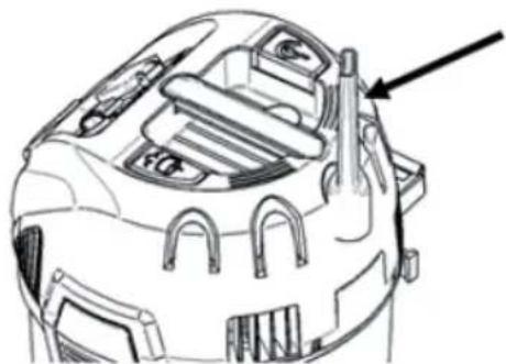
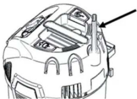
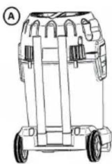
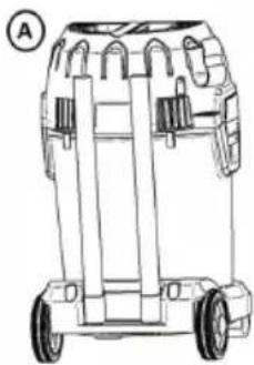
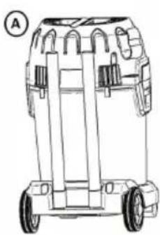
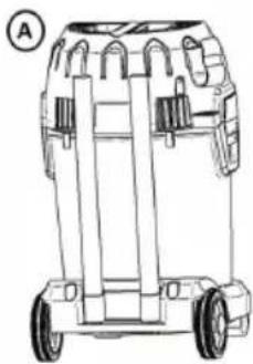
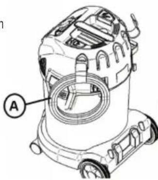
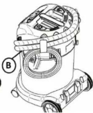
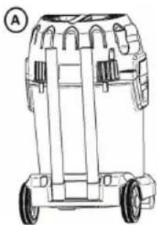
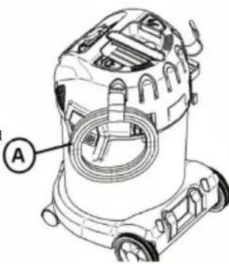
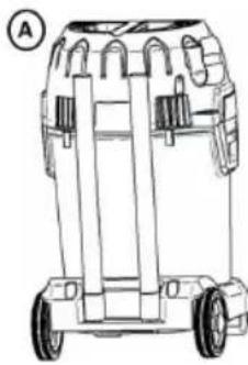
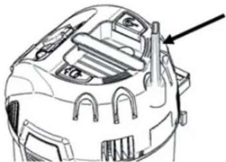
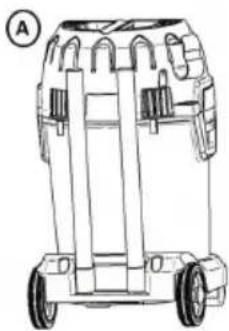
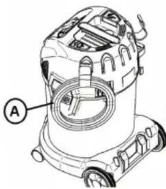
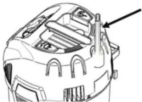
The tubes can be stored either single (A) on the back of the machine e.g. when the machine is being moved from one place to the other or together (B) via the parking hook/function in between use
natural_image
Technical line drawing of a mechanical component with no visible text or symbolsFig. 21
natural_image
Line drawing of a wheeled cart or vehicle chassis with wheels and structural supports (no text or symbols)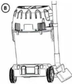
natural_image
Line drawing of a wheeled cart with wheels and a handle, no text or symbols presentFig. 20
The nozzles can be stored in the accessory holders on the head
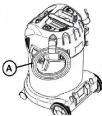
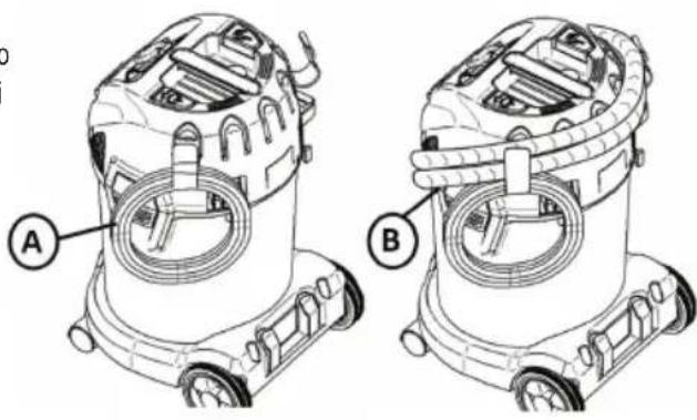
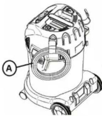
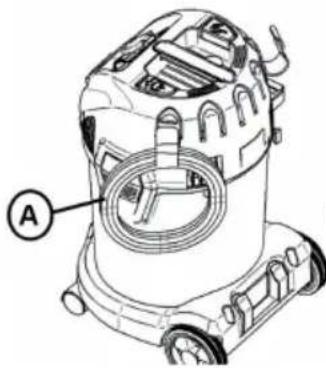
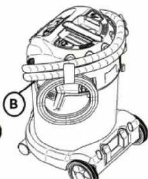
For machine without cord rewinder the cord (A) can be stored in the hooks. These hooks can also be used for storing the hose (B) by coiling it around the machine
natural_image
Line drawing of a compact vacuum cleaner with wheels and control knobs (no text or symbols)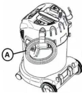
natural_image
Line drawing of a vacuum cleaner with labeled component A (no text or symbols beyond label)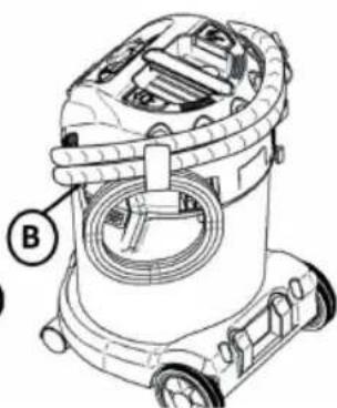
natural_image
Technical line drawing of a vacuum cleaner with labeled component B (no text or symbols beyond label)Fig. 22
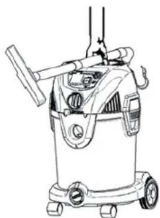
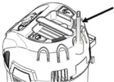
When transporting from one place to another the tubes can be put on the handle as seen on figure
Fig. 23
WARNING! When not in use: disconnect the power cord from the electrical outlet.
7 TROUBLE SHOOTING
Repair or service of electrical components such as cord or motor, must only be carried out by an authorized service center.
| Vacuum does not start: | •Check to see that the plug is correctly inserted in the electrical outlet and that there is power at receptacle.•A circuit breaker may have tripped. Check the circuit breaker box.•The cord or plug may be damaged. Call the Customer Service Department to get the nearest authorized service center. |
| Motor does not run in automatic mode | •Power tool defective or not connected properly. Check that the power tool works or that the plug is inserted correctly.•The power rating of the electrical tool is too low. Note that minimum power rating is P>100W |
| Motor stops: •A thermal overload protector will shut off the motor if the motor temperature is too high. If this occurs, turn the switch off. Wait 5-10 minutes for the motor to cool. Turn switch on and resume operation. | |
| Suction power is reduced: | •The tank may be full and needs to be emptied. See chapter 4.8•The wands, hose and nozzle may be clogged and need to be cleaned.•Any of the above may be damaged and need to be replaced.•The filter may be clogged. Use the Filter Cleaning System (see chapter 5), to clean the filter.•Replace the filter or make sure the filter is installed properly.•The hose connection is loose and need to be tightened. |
| Static shocks: | •If the environment is too dry, add moisture to air. If possible, use a humidifier.•Use conductive hose if machine is anti-static prepared•In case the relative humidity of air is low, please note that this situation will not have any effect on use of the vacuum cleaner. |
| Warning light and buzzer goes on (M-Class and H-Class) | •Check that the hose size is adjusted to the correct size of hose used•See “suction power is reduced”•Check that the power control is not adjusted too low for the application |
8 WARRANTY
Warranty covers:
This vacuum cleaner is warranted for 2 years. This warranty includes spare parts and labor costs, and covers manufacturing and material defects that may occur during normal use. This warranty does not include normal wear and tear.
Service under this warranty will only be performed with proof that the defect occurred within the warranty period and that the vacuum cleaner was purchased as a new product. Proof would be a cash register receipt with date and product type. Contact your specialist dealer in the event of a warranty/repair case.
Warranty does not cover:
•Normal wear and tear of accessories, filters and motors.
- Defects or damage occurring as a direct or indirect result of incorrect use - such as the vacuuming of rubble, or carpet deodorant powder (read safety warnings and instructions)
•Abuse due to failure to follow instructions in the user manual.
- Incorrect or poor configuration, i.e. setting up or improper connection, fire-damage, fire, lightning strike or unusual voltage fluctuations or any other electrical disturbances. Electrical disturbances include a defective circuit breaker or defective electrical installations on the supply grid.
Warranty becomes void:
- If a failure is caused by the use of non-original filters.
- If the model, item or any identity/serial number is removed from the vacuum cleaner.
- If the vacuum cleaner has been repaired by a non-authorized dealer.
! WARNING – If any of the motor housing parts should become detached or broken, operations should be discontinued immediately to avoid personal injury. Repairs should be made before reuse.
Note: FOR TECHNICAL ASSISTANCE, CONTACT YOUR SPECIALIST DEALER OR OUR CUSTOMER SERVICE DEPARTMENT.
9 DECLARATION OF CONFORMITY
| We hereby declare that the machine described below complies with the relevant basic safety and health requirements of the EC Directives, both in its basic design and construction as well as in the version put into circulation by us. This declaration shall cease to be valid if the machine is modified without our prior approval | |
| Product: Vacuum cleaner for wet and dry operation | |
| Type: Energetic | |
| The design of the appliance corresponds to the following pertinent regulations: | EC-Machinery Directive 2006/42/EUEC-Directive EMV 2014/30/EUROHS 2011/65/EU |
| Applied harmonised standards: EN 60335-1:2012+A11:2014+AC:2014+A13:2017, EN 60335-2-69:2016,EN 55014-1:2006+A1+A2, EN 55014-2:1997+A1+A2,EN 61000-3-2:2006+A1+A2, EN 61000-3-3:2008EN62233:2008 | |
| Applied international standards and technical specifications: | IEC 60335-2-69:2016 in conjunction with IEC 60335-1:2010, COR1:2010,COR2:2011, AMD1:2013, COR1:2014, AMD2:2016 |
| Authorized documentation representative | ELECTROSTAR GmbH, Hans-Zinser-Straße 1-3, 73061 Ebersbach/Fils, Germany |
| 06.12.2021 Carsten Gresser |  Head of Quality Assurance Head of Quality Assurance |
10 PRODUCT SPECIFICATIONS
| ENERGETIC | ||
| Model name 1430 1420 | ||
| Voltage 220-240 V 220-240 V | ||
| Frequency 50-60 Hz 50-60 Hz | ||
| Power IEC 1400 W 1400 W | ||
| Connected load for appliance socket | 2200 W 2200 W | |
| Total Power 3600 W 3600 W | ||
| Protection Class I I | ||
| Volume air flow 70 l/s 70 l/s | ||
| Negative pressure 210 hpa | 210 hpa | |
| Type of protection IPX4 | IPX4 | |
| Tank volume | 30 l | 20 l |
| Vibration | < 2.5 m/s2 | < 2.5 m/s2 |
| Sound pressure level at a distance of 1 m, EN 60704-1 | 76 +/-2 dB(A) | 76 +/-2 dB(A) |
| Working sound level | 86 +/-2 dB(A) | 86 +/-2 dB(A) |
| Weight | 12,0 kg | 10,6 kg |
| Dimensions L x W x H | 405 x 375 x 612 mm | 405 x 375 x 492 mm |
11 CUSTOMER SERVICE
For technical assistance or service parts, contact your specialist dealer or the Customer Service Department at: www.starmix.de
12 SPARE PARTS
ATTENTION: Use only original accessories.
| Article name | Order.-No. | |
| Filter cartridge FPP 3500, WS | PET, H13, 3500 cm2, Dust class M | 460727 |
| Filter cartridge FPP 5000 HEPA, WS | PET, HEPA H14, 5000 cm2, Dust class H | 460475 |
| Emptying bag FBV 30, WS (5 pcs) | Fleece Bag 30 l, Dust class M | 460772 |
| Emptying bag FBVPE 30, WS (5 pcs) | PE Bag with fleece insert 30 l, Dust class H | 460482 |
| Emptying bag FBVPE 20, WS (5 pcs) | PE Bag with fleece insert 20 l, Dust class H | 460734 |
NOTE
Old equipment contains valuable materials which are designed for re-processing. The vacuum cleaners must not be thrown away in the normal household waste, but should be disposed of at a suitable proper collection system, e.g. via your communal disposal location.
Français
⚠️ DANGER!
III.4
3.3 PRÉPARATION DE L'ÉTRIER DE CONDUITE (EN OPTION)
4 UTILISATION DE L'ASPIRATEUR
natural_image
Line drawing of a vacuum cleaner with control panel and wheels (no text or symbols)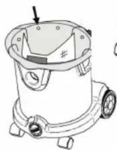
natural_image
Line drawing of a mechanical device with no visible text or symbolsIII. 6B
natural_image
Technical line drawing of a mechanical device with no visible text or symbolsIII. 6A
III.7
4.2 ASPIRATION À SEC OU PAR VOIE HUMIDE
natural_image
Technical line drawing of a mechanical device with labeled component (no text or symbols present)4.4 SOUFFLAGE (CLASSE DE POUSSIÈRE L UNIQUEMENT) - INSÉRER ET RETIRER LE TUYAU
4.8 VIDANGE DU COLLECTEUR DE POUSSIÈRES/DÉBRIS (POUR LES APPAREILS DE LA CLASSE DE POUSSIÈRE L)
natural_image
Line drawing of a hand operating a machine with a labeled component (no text or symbols present)III. 13
4.9 REMPLACEMENT DU SAC DE SÉCURITÉ POUR LES APPAREILS DE CLASSE H
DANGER
natural_image
Line drawing of a vacuum cleaner with a mesh bag and a separate close-up of its cap (no text or symbols)III. 14
4.10 RÉGLAGE DU DIAMÈTRE DU TUYAU (EN OPTION)
flowchart
graph TD
    A["Dissection with cap"] --> B["Assembly of sput"]
    B --> C["Sputter with caps"]
    C --> D["Packaging with bag"]
III. 16
5 NETTOYAGE DU FILTRE
III. 17
5.2 NETTOYAGE SEMI-AUTOMATIQUE DU FILTRE (EN OPTION)
natural_image
Technical line drawing of a mechanical component with no visible text or symbolsIII. 21
natural_image
Line drawing of a wheeled cart or container with wheels and side compartments (no text or symbols)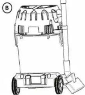
natural_image
Line drawing of a wheeled cart with wheels and a handle, no text or symbols presentIII. 20
natural_image
Line drawing of a compact water purifier with wheels and control panel (no text or symbols)III. 23
natural_image
Technical line drawings of two vacuum cleaner units labeled A and B, showing internal components and mounting brackets (no text or symbols beyond labels)III. 22
9 DÉCLARATION DE CONFORMITÉ CE
Fig. 4
natural_image
Line drawing of a vacuum cleaner with control panel and wheels (no text or symbols)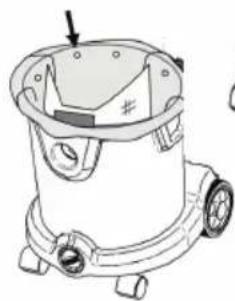
natural_image
Line drawing of a mechanical device with gears and a handle (no text or symbols)Fig. 6B
natural_image
Technical line drawing of a mechanical device with a central component and mounting base (no text or symbols)Fig. 6A
Fig. 7
natural_image
Technical line drawing of a mechanical device with labeled component 'C' (no text or symbols beyond label)4.4 SOPLAR (SOLO CLASE DE POLVO L): COLOCAR Y QUITAR LA MANGUERA
4.8 VACIADO DEL RECIPIENTE PARA POLVO/RESIDUOS (SOLO PARA MÁQUINAS DE LA CLASE DE POLVO L)
Fig. 13
4.9 CAMBIO DEL SACO COLECTOR EN MÁQUINAS CON CLASE DE POLVO H
PELIGRO
natural_image
Line drawing of a vacuum cleaner with a bag and handle, alongside a simple sketch of the same device (no text or symbols)Fig. 14
4.10 AJUSTE DEL DIÁMETRO DE LA MANGUERA (OPCIONAL)
Fig. 17
5.2 LIMPIEZA DE FILTRO SEMIAUTOMÁTICA (OPCIONAL)
natural_image
Technical line drawing of a mechanical component with no visible text or symbolsFig. 21
natural_image
Line drawing of a mechanical device with wheels and a top component (no text or symbols)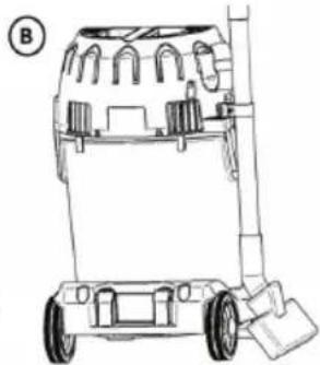
natural_image
Line drawing of a wheeled vehicle chassis with wheels and structural components (no text or symbols)Fig. 20
natural_image
Line drawing of a compact water purifier with wheels and control panel (no text or symbols)Fig. 23
natural_image
Line drawing of a vacuum cleaner with labeled component A (no text or symbols beyond label)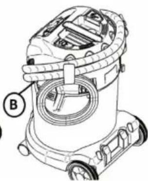
natural_image
Technical line drawing of a vacuum cleaner with labeled component B (no text or symbols beyond label)Fig. 22
Fig. 4:
Fig. 5:
natural_image
Line drawing of a vacuum cleaner with control panel and wheels (no text or symbols)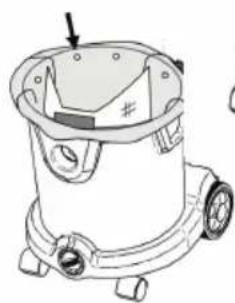
natural_image
Line drawing of a mechanical device with no visible text or symbolsFig. 6B
natural_image
Technical line drawing of a mechanical device with a central component and mounting base (no text or symbols)Fig. 6A
Fig. 7:
4.3 ASPIRAR - INSERIR E REMOVER A MANGUEIRA
natural_image
Technical line drawing of a mechanical device with labeled component (no text or symbols)Fig. 8:
4.4 SOPRAR (APENAS CLASSE DE PÓ L) - INSERIR E REMOVER A MANGUEIRA
4.8 ESVAZIAR O RECIPIENTE DE PÓ/ENTULHO (PARA MÁQUINAS DA CLASSE DE PÓ L)
natural_image
Line drawing of a hand operating a machine with a labeled component (no text or symbols present)Fig. 13
4.9 TROCAR O SACO DO PÓ DE SEGURANÇA PARA MÁQUINAS DA CLASSE DE PÓ H PERIGO
natural_image
Line drawing of a vacuum cleaner with a bag and handle, alongside a simple sketch of the same device (no text or symbols)Fig. 14
flowchart
graph TD
    A["Dissection with cap"] --> B["Cut into part"]
    B --> C["Fill with cap"]
    C --> D["Inserted part"]
    D --> E["Fill with cap"]
    E --> F["Bag filled with bag"]
Fig. 16
5 LIMPEZA DO FILTRO
Fig. 17
5.2 LIMPEZA SEMI-AUTOMÁTICA DO FILTRO (OPCIONAL)
natural_image
Technical line drawing of a mechanical component with no visible text or symbolsFig. 21
natural_image
Line drawing of a wheeled cart or container with wheels and side panels (no text or symbols)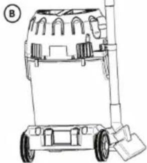
natural_image
Line drawing of a wheeled cart with wheels and a handle (no text or symbols)Fig. 20
natural_image
Line drawing of a compact water purifier with wheels and control panel (no text or symbols)Fig. 23
natural_image
Technical line drawing of a vacuum cleaner with labeled component B (no text or symbols beyond label)Fig. 22
Fig. 4
Fig. 5
4 UTILIZZO DELL'ASPIRATORE
4.1 LAVORI CON SACCHETTI RACCOGLIPOLVERE
natural_image
Line drawing of a vacuum cleaner with control panel and wheels (no text or symbols)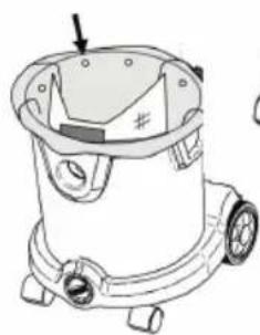
natural_image
Line drawing of a mechanical device with no visible text or symbolsFig. 6B
natural_image
Technical line drawing of a mechanical device with a central component and mounting base (no text or symbols)Fig. 6A
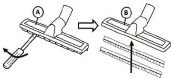
Fig. 7
natural_image
Technical line drawing of a mechanical device with labeled component (no text or symbols)Fig. 8
4.4 SOFFIAGGIO (SOLO CLASSE DI POLVERI L) - INSERIRE E RIMUOVERE IL TUBO FLESSIBILE
4.8 SVUOTAMENTO DEL CONTENITORE PER POLVERE/CIOTTOLI (NELLE MACCHINE DELLA CLASSE DI POLVERI L)
Fig. 13
4.9 SOSTITUZIONE DEL SACCO RACCOGLIPOLVERE DI SICUREZZA PER LE MACCHINE DELLA CLASSE DI POLVERI H
PERICOLO
natural_image
Line drawing of a vacuum cleaner with a mesh bag and a separate close-up of its cap (no text or symbols)Fig. 14
4.10 IMPOSTAZIONE DEL DIAMETRO DEL TUBO FLESSIBILE (OPZIONALE)
flowchart
graph TD
    A["Dissection with cap"] --> B["Assembly of sput"]
    B --> C["Sputing into a cup"]
    C --> D["Packaging with suture bag"]
Fig. 16
5 PULIZIA DEL FILTRO
Fig. 17
5.2 PULIZIA SEMIAUTOMATICA DEL FILTRO (OPZIONALE)
natural_image
Technical line drawing of a mechanical component with no visible text or symbolsFig. 21
natural_image
Line drawing of a mechanical device with wheels and internal compartments (no text or symbols)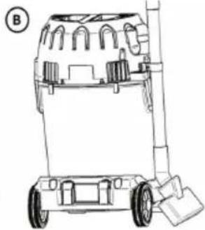
natural_image
Line drawing of a wheeled cart with wheels and a handle, no text or symbols presentFig. 20
natural_image
Line drawing of a compact water purifier with wheels and control panel (no text or symbols)attorno a
natural_image
Technical line drawing of a vacuum cleaner with labeled component A (no text or symbols beyond label)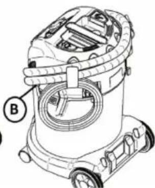
natural_image
Technical line drawing of a vacuum cleaner with labeled component B (no text or symbols beyond label)Fig. 22
La garanzia include:
Fig. 4
3.3 VOORBEREIDING VAN DE DUWBEUGEL (OPTIONEEL)
Fig. 5
4 GEBRUIK VAN DE STOFZUIGER
4.1 WERKEN MET STOFZAKKEN
natural_image
Line drawing of a vacuum cleaner with control panel and wheels (no text or symbols)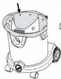
natural_image
Line drawing of a vacuum cleaner with mounting feet and a handle (no text or symbols)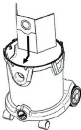
natural_image
Technical line drawing of a mechanical device with no visible text or symbolsFig. 6A
Fig. 6B
4.2 DROGE OF NATTE VLOERAFZUIGING
Fig. 7
4.3 STOFZUIGEN - INBRENGEN EN UITNEMEN VAN DE SLANG
natural_image
Line drawing of a car air purifier with labeled component (no text or symbols)4.4 UITBLAZEN (ALLEEN STOFKLASSE L) - INBRENGEN EN UITNEMEN VAN DE SLANG
4.8 LEDIGEN VAN HET STOF-/AFVALRESERVOIR (VOOR MACHINES VAN STOFKLASSE L)
Fig. 13
4.9 VERWISSELEN VAN DE VEILIGHEIDSSTOFZAK VOOR MACHINES VAN STOFKLASSE H GEVAAR
natural_image
Line drawing of a vacuum cleaner with a bag and handle, alongside a separate sketch of a mallet (no text or symbols)Fig. 14
4.10 AANPASSEN VAN DE SLANGDIAMETER (OPTIONEEL)
flowchart
graph TD
    A["Dissection with cap"] --> B["Shipment with screwdriver"]
    B --> C["Sash Bag Application"]
    C --> D["Shipment with cup and needle"]
Fig. 16
5 FILTERREINIGING
Fig. 17
5.2 HALFAUTOMATISCHE FILTERREINIGING (OPTIONEEL)
natural_image
Technical line drawing of a mechanical component with no visible text or symbolsFig. 21
natural_image
Line drawing of a wheeled cart or container with wheels and internal compartments (no text or symbols)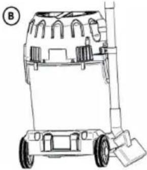
natural_image
Line drawing of a wheeled cart with wheels and internal compartments (no text or symbols)Fig. 20
natural_image
Line drawing of a compact water purifier with wheels and control panel (no text or symbols)Fig. 23
natural_image
Line drawing of a vacuum cleaner with labeled component A (no text or symbols beyond label)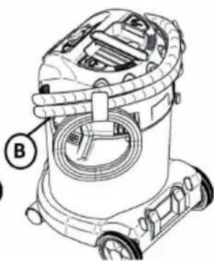
natural_image
Technical line drawing of a vacuum cleaner with labeled component B (no text or symbols beyond label)Fig. 22
natural_image
Diagram of a car's front dashboard with arrows indicating parts of the engine and airbags (no text or labels)Fig. 4
3.3 FORBEREDELSE AF DRIVSTANGEN (OPTIONALT)
4 BRUG AF ST∅VSUGEREN
4.1 ARBEJDE MED ST∅VPOSER
natural_image
Line drawing of a vacuum cleaner with control panel and wheels (no text or symbols)Fig. 6B
natural_image
Line drawing of a mechanical device with no visible text or symbols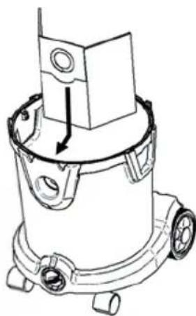
natural_image
Technical line drawing of a mechanical device with a central component and mounting base (no text or symbols)Fig. 6A
4.2 T∅R ELLER VÅD GULVUDTRÆKNING
4.3 ST∅VSUGNING - INDSÆTTELSE OG FJERNELSE AF SLANGEN
natural_image
Line drawing of a mechanical device with labeled component 'C' (no text or symbols beyond label)4.4 UDBLÆSNING (KUN ST∅VKLASSE L) - INDSÆTTELSE OG FJERNELSE AF SLANGEN
4.8 T∅MNING AF ST∅V-/
AFFALDSBEHOLDEREN (FOR MASKINER I ST∅VKLASSE L)
natural_image
Line drawing of a hand operating a manual machine with a labeled component (no text or symbols present)4.9 UDSKIFTNING AF SIKKERHEDSST∅VPOSEN TIL MASKINER I ST∅VKLASSE H
FARE
natural_image
Line drawing of a vacuum cleaner with a bag and handle, alongside a separate sketch of a mallet (no text or symbols)Fig. 14
4.10 JUSTERING AF SLANGENS DIAMETER (OPTIONALT)
flowchart
graph TD
    A["Implant with internal cavities"] --> B["Sash Bag"]
    B --> C["Check the part"]
    C --> D["Check the body part"]
Fig.16
5 RENSNING AF FILTER
Fig. 17
5.2 HALVAUTOMATISK FILTERRENSNING (OPTIONALT)
natural_image
Line drawing of a mechanical device with wheels and internal components (no text or symbols)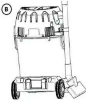
natural_image
Line drawing of a wheeled cart with wheels and a handle, no text or symbols presentFig. 20
natural_image
Technical line drawing of a mechanical component with no visible text or symbolsFig. 21
natural_image
Line drawing of a compact vacuum cleaner with wheels and control knobs (no text or symbols)Fig. 22
natural_image
Technical line drawing of a vacuum cleaner with labeled component A (no text or symbols beyond label)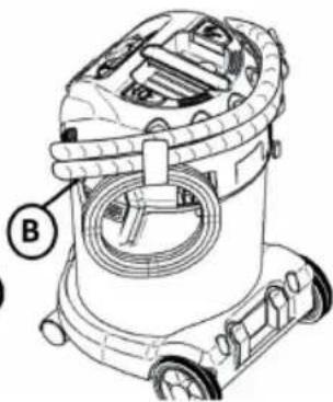
natural_image
Technical line drawing of a vacuum cleaner with labeled component B (no text or symbols beyond label)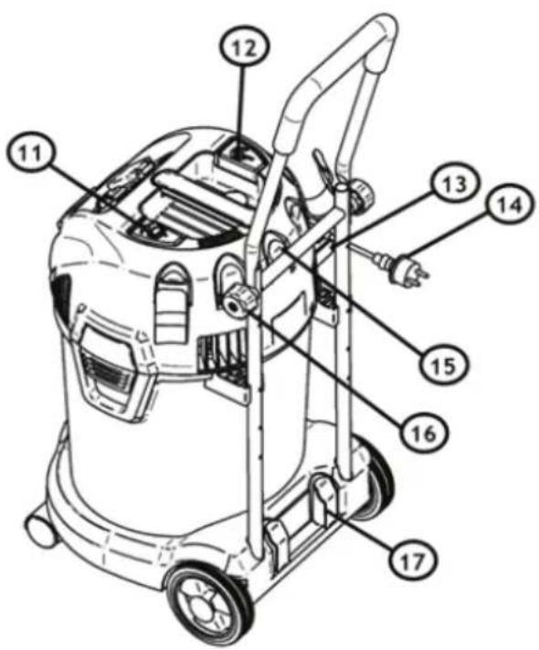
Illustration 4
3.3 FÖRBEREDELSE AV KÖRBYGELN (TILLVAL)
4 ANVÄNDNING AV DAMMSUGAREN
4.1 ARBETE MED DAMMPÅSAR
natural_image
Line drawing of a vacuum cleaner with control panel and wheels (no text or symbols)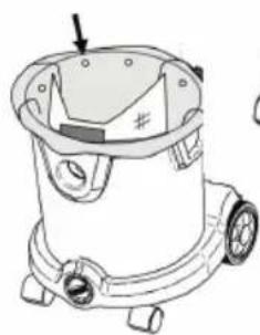
natural_image
Line drawing of a mechanical device with no visible text or symbolsIllustration 6B
natural_image
Technical line drawing of a mechanical device with a central component and mounting base (no text or symbols)Illustration 6A
4.2 TORR- ELLER VÅT GOLVDAMMSUGNING
4.3 DAMMSUGA – ISÄTTNING OCH BORTTAGNING AV SLANGEN
natural_image
Technical line drawing of a mechanical device with labeled component 'c' (no text or symbols beyond label)4.4 UTBLÅSNING (ENDAST DAMMKLASS L) – ISÄTTNING OCH BORTTAGNING AV SLANGEN
4.8 TÖMNING AV BEHÅLLAREN FÖR DAMM/ SKRÄP (PÅ MASKINER I DAMMKLASS L)
natural_image
Line drawing of a hand operating a machine with a labeled component (no text or symbols present)Illustration 13
4.9 BYTE AV SÄKERHETSDAMMSÄCKEN FÖR MASKINER I DAMMKLASS H
FARA
natural_image
Line drawing of a vacuum cleaner with a bag and handle, alongside a simple sketch of the same device (no text or symbols)Illustration 14
4.10 INSTÄLLNING AV SLANGDIAMETERN (TILLVAL)
flowchart
graph TD
    A["Internal Component"] --> B["Close-up of Lens"]
    B --> C["Close-up of Cap"]
    C --> D["Magnified Bag"]
5 FILTERRENGÖRING
Illustration 17
5.2 HALVAUTOMATISK FILTERRENGÖRING (TILLVAL)
natural_image
Line drawing of a mechanical device with wheels and a top component (no text or symbols)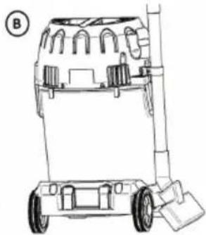
natural_image
Line drawing of a wheeled vehicle chassis with wheels and support structure (no text or symbols)Illustration 20
natural_image
Technical line drawing of a mechanical component with no visible text or symbolsIllustration 21
natural_image
Line drawing of a vacuum cleaner with wheels and control knobs (no text or symbols)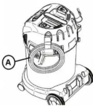
natural_image
Technical line drawing of a vacuum cleaner with labeled component A (no text or symbols beyond label)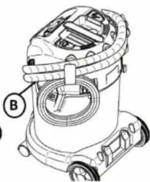
natural_image
Technical line drawing of a vacuum cleaner with labeled component B (no text or symbols beyond label)Illustration 22
Fig. 4
3.3 KLARGJ∅RING AV KJ∅REHÅNDTAK (VALGFRITT)
Fig. 5
4 BRUK AV ST∅VSUGEREN
4.1 ARBEIDE MED ST∅VPOSER
natural_image
Line drawing of a vacuum cleaner with control panel and wheels (no text or symbols)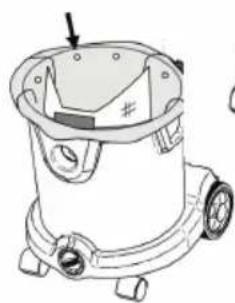
natural_image
Line drawing of a mechanical device with no visible text or symbols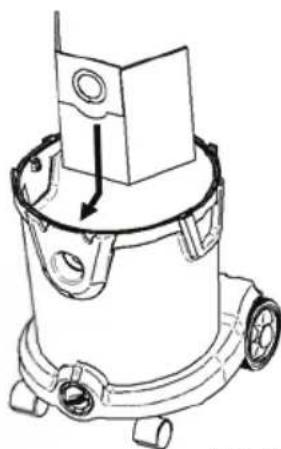
natural_image
Technical line drawing of a mechanical device with a central component and mounting base (no text or symbols)Fig. 6A
Fig. 6B
4.2 T∅RR- ELLER VÅTSUGING AV GULV
Fig. 7
4.3 ST∅VSUGNING - PÅSETTING OG FJERNING AV SLANGEN
Sett slangen (A) inn i sugeinntaket (B) for å støvsuge.
natural_image
Technical line drawing of a mechanical device with labeled component (no text or symbols present)Fig. 8
4.4 UTBLÅSING (KUN ST∅VKLASSE L) – PÅSETTING OG FJERNING AV SLANGEN
4.5 SLÅ PÅ APPARATET
4.7 T∅MMING AV VÆSKEN I BEHOLDEREN
4.8 T∅MMING AV BEHOLDEREN FOR ST∅V/GRUS (PÅ MASKINER I ST∅VKLASSE L)
natural_image
Line drawing of a hand operating a machine with a labeled component (no text or symbols present)Fig. 13
4.9 BYTTE AV SIKKERHETSST∅VPOSE FOR MASKINER I ST∅VKLASSE H
FARE
natural_image
Line drawing of a vacuum cleaner with a bag and handle, alongside a simple sketch of its back cover (no text or symbols)Fig. 14
4.10 JUSTERING AV SLANGEDIAMETER (VALGFRITT)
flowchart
graph TD
    A["Patient with surgical implant"] --> B["Surgical component"]
    B --> C["Saybag with internal components"]
    C --> D["Sash bag with internal parts"]
Fig. 16
5 FILTERRENGJ∅RING
Fig. 17
5.2 HALVAUTOMATISK FILTERRENGJ∅RING (VALGFRITT)
natural_image
Technical line drawing of a mechanical component with no visible text or symbolsFig. 21
natural_image
Line drawing of a wheeled cart or container with wheels and compartments (no text or symbols)
natural_image
Line drawing of a wheeled cart with wheels and a handle (no text or symbols)Fig. 20
natural_image
Line drawing of a compact vacuum cleaner with wheels and control knobs (no text or symbols)Fig. 23
natural_image
Line drawing of a vacuum cleaner with labeled component A (no text or symbols beyond label)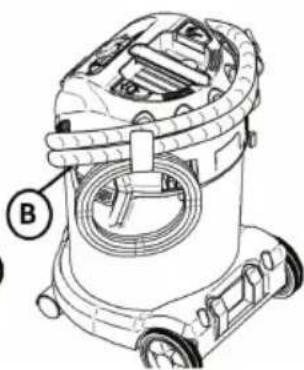
natural_image
Technical line drawing of a vacuum cleaner with labeled component B (no text or symbols beyond label)Fig. 22
Kuva 4
Kuva 5
4 IMURIN KÄYTTÖ
4.1 PÖLYPUSSIEN KÄSITTELY
natural_image
Line drawing of a vacuum cleaner with control panel and wheels (no text or symbols)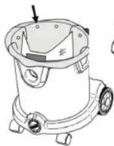
natural_image
Line drawing of a mechanical device with wheels and a handle (no text or symbols)Kuva 6B
natural_image
Technical line drawing of a mechanical device with no visible text or symbolsKuva 6A
4.2 LATTIAN MÄRKÄ- TAI KUIVAIMUROINTI
Kuva 7
4.3 IMUROINTI - LETKUN ASENTAMINEN JA POISTAMINEN
natural_image
Technical line drawing of a mechanical device with labeled component (no text or symbols)Kuva 8
4.4 ULOSPUHALLUS (VAIN PÖLYLUOKKA L) - LETKUN ASENTAMINEN JA POISTAMINEN
4.8 PÖLY-/ROSKASÄILIÖN TYHJENTÄMINEN (PÖLYLUOKAN L KONEET)
natural_image
Line drawing of a hand operating a machine with a labeled component (no text or symbols present)Kuva 13
4.9 TURVAPÖLYPUSSIN VAIHTAMINEN PÖLYLUOKAN H KONEISIIN
VAARA
natural_image
Line drawing of a vacuum cleaner with a bag and handle, alongside a simple sketch of the same device (no text or symbols)Kuva 14
4.10 LETKUN HALKAISIJAN SÄÄTÖ (VALINNAINEN)
flowchart
graph TD
    A["Implant with internal cavities"] --> B["Sash Bag"]
    B --> C["Check the part of the sash bag"]
    C --> D["Check the body part of the sash bag"]
Kuva 16
5 SUODATTIMEN PUHDISTAMINEN
Kuva 17
5.2 PUOLIAUTOMAATTINEN SUODATTIMEN PUHDISTAMINEN (VALINNAINEN)
natural_image
Technical line drawing of a mechanical component with no visible text or symbols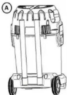
natural_image
Line drawing of a wheeled cart with wheels and compartments (no text or symbols)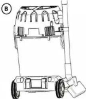
natural_image
Line drawing of a wheeled cart with wheels and a handle (no text or symbols)Kuva 20
Kuva 21
natural_image
Line drawing of a compact water purifier with wheels and control panel (no text or symbols)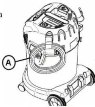
natural_image
Technical line drawing of a vacuum cleaner with labeled component A (no text or symbols beyond label)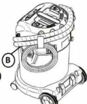
natural_image
Technical line drawing of a vacuum cleaner with labeled component B (no text or symbols beyond label)Kuva 22
Rys. 4
3.3 PRZYGOTOWANIE PAŁAKA PROWADZĄCEGO ODKURZACZA (OPCJONALNIE):
4 UŻYTKOWANIE ODKURZACZA
4.1 PRACA Z WORKAMI NA KURZ
natural_image
Line drawing of a vacuum cleaner with control panel and wheels (no text or symbols)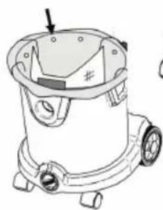
natural_image
Line drawing of a mechanical device with no visible text or symbols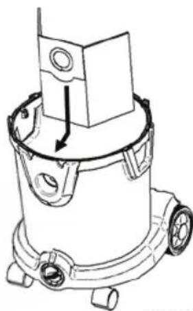
natural_image
Technical line drawing of a mechanical device with a central component and mounting base (no text or symbols)Rys. 6A
Rys. 6B
Rys. 7
natural_image
Technical line drawing of a mechanical device with labeled component (no text or symbols present)Rys. 8
4.4 WYDMUCHIWANIE (TYLKO KLASA PYŁU L) - WKŁADANIE I WYJMOWANIE WEŻA
4.8 OPRÓŻNIANIE ZBIORNIKA NA PYŁ/GRUZ (DLA MASZYN O KLASIE PYŁU L)
Rys. 13
4.9 WYMIANA WORKA NA KURZ W MASZYNACH O KLASIE PYŁU H
ZAGROŻENIE
natural_image
Line drawing of a vacuum cleaner with a bag and handle, alongside a simple sketch of the same device (no text or symbols)Rys. 14
4.10 REGULACJA ŚREDNICY WEŻA (OPCJONALNIE)
Rys. 17
5.2 PÓŁAUTOMATYCZNE CZYSZCZENIE FILTRA (OPCJONALNIE)
natural_image
Technical line drawing of a mechanical component with a hand pointing to a feature (no text or symbols present)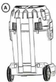
natural_image
Line drawing of a wheeled cart or container with multiple wheels and a handle (no text or symbols)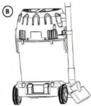
natural_image
Line drawing of a wheeled vehicle chassis with wheels and a handle (no text or symbols)Rys. 20
Rys. 21
natural_image
Line drawing of a compact water purifier with wheels and control panel (no text or symbols)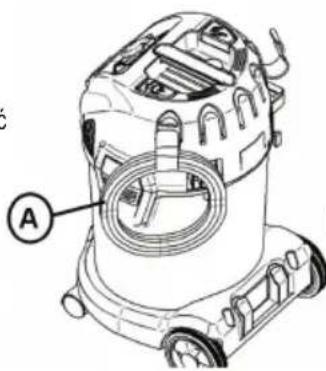
natural_image
Technical line drawing of a vacuum cleaner with labeled component A (no text or symbols beyond label)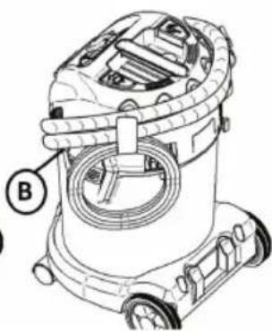
natural_image
Technical line drawing of a vacuum cleaner with labeled component B (no text or symbols beyond label)Rys. 22
- ábra
3.3 A HÚZÓKENGYEL ELŐKÉSZÍTÉSE (OPCIONÁLIS)
4 A PORSZÍVÓ HASZNÁLATA
4.1 PORZSÁKOKKAL VALÓ MUNKAVÉGZÉS
natural_image
Line drawing of a vacuum cleaner with control panel and wheels (no text or symbols)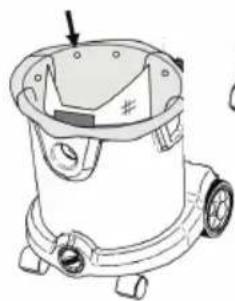
natural_image
Line drawing of a mechanical device with wheels and a handle (no text or symbols)6B. ábra
natural_image
Technical line drawing of a mechanical device with no visible text or symbols6A. ábra
- ábra
natural_image
Technical line drawing of a mechanical device with labeled component (no text or symbols)4.8 A POR-/TÖRMELÉKTARTÁLY KIÜRÍTÉSE (L POROSZTÁLYÚ GÉPEKNÉL)
- ábra
4.9 BIZTONSÁGI PORZSÁK CSERÉJE H POROSZTÁLYÚ GÉPEKNÉL
VESZÉLY
natural_image
Line drawing of a vacuum cleaner with a bag and handle, alongside a simple sketch of its back cover (no text or symbols)- ábra
flowchart
graph TD
    A["Dissection with cap"] --> B["Cut into part"]
    B --> C["Fill with cap"]
    C --> D["Inserted part"]
    D --> E["Fill with bag"]
- ábra
5 SZÜRÖTISZTÍTÁS
- ábra
natural_image
Technical line drawing of a mechanical component with no visible text or symbols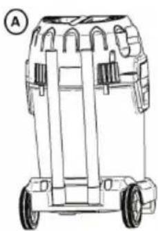
natural_image
Line drawing of a wheeled cart or container with wheels and compartments (no text or symbols)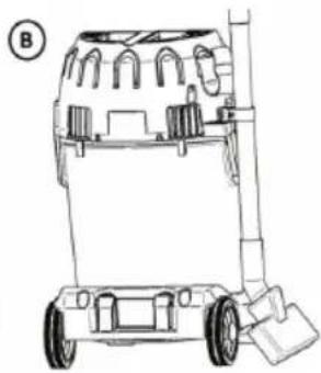
natural_image
Line drawing of a wheeled vehicle chassis with wheels and a handle (no text or symbols)- ábra
21. ábra
natural_image
Line drawing of a compact vacuum cleaner with wheels and control knobs (no text or symbols)
natural_image
Technical line drawing of a vacuum cleaner with labeled component A (no text or symbols beyond label)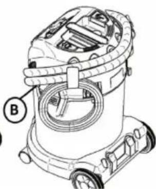
natural_image
Technical line drawing of a vacuum cleaner with labeled component B (no text or symbols beyond label)- ábra
Obr. 4
3.3 PŘÍPRAVA RUKOJETI (VOLITELNĚ)
4 POUŽITÍ VYSAVAČE
4.1 PRÁCE S PRACHOVÝMI SÁČKY
natural_image
Line drawing of a vacuum cleaner with control panel and wheels (no text or symbols)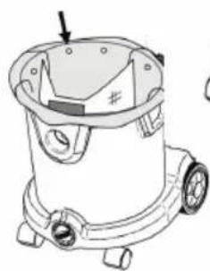
natural_image
Line drawing of a mechanical device with no visible text or symbolsObr. 6B
natural_image
Technical line drawing of a mechanical component with a downward arrow indicating motion (no text or symbols)Obr. 6A
4.2 VYSÁVÁNÍ SUCHÉ NEBO MOKRÉ PODLAHY
Obr. 7
4.3 VYSÁVÁNÍ PRACHU - VLOŽENÍ A VYJMUTÍ HADICE
natural_image
Technical line drawing of a car air purifier with labeled component (no text or symbols present)4.4 VYFUKOVÁNÍ (POUZE TŘÍDA PRACHU L) - NASAZENÍ A VYJMUTÍ HADICE
4.5 ZAPNUTÍ PŘÍSTROJE
4.8 VYPRÁZDNĚNÍ NÁDOBY NA PRACH/NEČISTOTY (PRO STROJE TŘÍDY PRACHU L)
natural_image
Line drawing of a hand operating a mechanical device with a labeled component (no text or symbols present)Obr. 13
4.9 VÝMĚNA BEZPEČNOSTNÍHO SÁČKU NA PRACH PRO STROJE TŘÍDY PRACHU H
NEBEZPEČÍ
natural_image
Line drawing of a vacuum cleaner with a bag and handle, alongside a simple sketch of the same device (no text or symbols)Obr. 14
4.10 NASTAVENÍ PRŮMĚRU HADICE (VOLITELNÉ)
Obr. 17
5.2 POLOAUTOMATICKÉ ČIŠTĚNÍ FILTRU (VOLITELNÉ)
natural_image
Line drawing of a mechanical device with wheels and a handle (no text or symbols)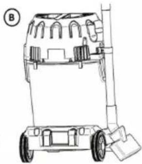
natural_image
Line drawing of a wheeled vehicle chassis with wheels and a support structure (no text or symbols)Obr. 20
natural_image
Technical line drawing of a mechanical component with no visible text or symbolsObr. 21
natural_image
Line drawing of a compact vacuum cleaner with wheels and control knobs (no text or symbols)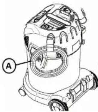
natural_image
Technical line drawing of a vacuum cleaner with labeled component B (no text or symbols beyond label)Obr. 22
natural_image
Diagram of a car's front dashboard with labeled parts and arrows indicating movement (no text or symbols present)Рисунок 4
natural_image
Line drawing of a vacuum cleaner with control panel and wheels (no text or symbols)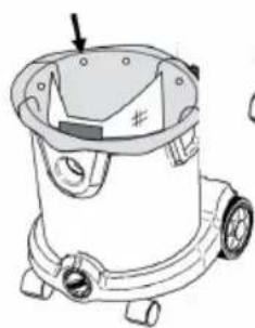
natural_image
Line drawing of a vacuum cleaner with mounting feet and a handle (no text or symbols)Рисунок 6В
natural_image
Line drawing of a car air purifier with labeled component (no text or symbols)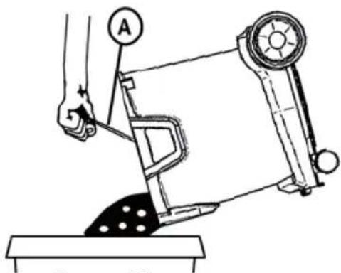
Рисунок 13
natural_image
Line drawing of a vacuum cleaner with a bag and handle, alongside a separate sketch of a mallet (no text or symbols)Рисунок 14
flowchart
graph TD
    A["Dissection with cap"] --> B["Assembly of a capsule"]
    B --> C["Sputtering with a bag"]
    C --> D["Packaging with a needle"]
Рисунок 16
5 ОЧИСТКА ФИЛЬТРА
Рисунок 17
5.2 ПОЛУАВТОМАТИЧЕСКАЯ ОЧИСТКА ФИЛЬТРА (ОПЦИЯ)
natural_image
Technical line drawing of a mechanical component with no visible text or symbols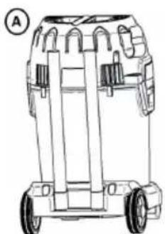
natural_image
Line drawing of a wheeled cart with wheels and side-mounted equipment (no text or symbols)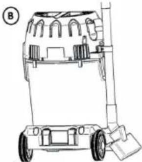
natural_image
Line drawing of a wheeled cart with wheels and a handle (no text or symbols)natural_image
Line drawing of a compact vacuum cleaner with wheels and control panel (no text or symbols)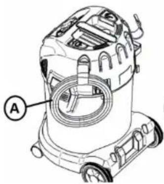
natural_image
Technical line drawing of a vacuum cleaner with labeled component A (no text or symbols beyond label)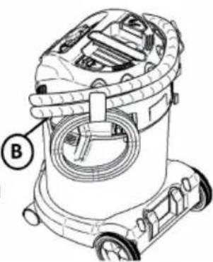
natural_image
Technical line drawing of a vacuum cleaner with labeled component B (no text or symbols beyond label)Рисунок 22
Class L vacuum devices are suitable for aspiration/clearing of dry, non-combustible dusts and hazardous dusts with occupational expo- sure limit values (AGW) > 1 mg/m ^3 .
Class M vacuum devices are suitable for aspiration/clearing of dry, non-combustible dusts, non-combustible liquids, wood dusts and hazardous dusts with workplace limit values of ≥ 0.1 mg/m ^3
Class H vacuum devices are suitable for aspiration/clearing of dry, non-combustible dusts, carcinogenic and pathogenic particles as well as non-combustible liquids, wood dusts and toxic dusts with all workplace limit values.
WARNING: This machine contains harmful dust. Emptying and maintenance, including removing the dust collection container, may only be performed by specialist staff who are wearing the appropriate personal protective equipment. Never operate without a complete filtration system.
- TROCKEN- ODER NASSBODENABSAUGUNG
- EINSTELLEN DES
- SCHLAUCHDURCHMESSERS (OPTIONAL)
- FILTERREINIGUNG
- HALBAUTOMATISCHE FILTERREINIGUNG (OPTIONAL)
- ⚠️ DANGER!
- DANGER!
- ⚠ WARNING!
- Before use
- IMPORTANT SAFETY INSTRUCTIONS
- SYMBOLS USED ON THE MACHINE
- WARNING
- HAZARDS LEVELS
- DANGER
- CAUTION
- SAFETY INSTRUCTIONS
- 1.4 POWER CORD
- APPLICATION
- OPERATION
- TRANSPORT
- MAINTENANCE
- ATTENTION
- SAFETY DEVICES
- Warning light and sound
- Tests and approvals
- OVERVIEW
- FIRST TIME SET UP INSTRUCTIONS
- ACCESSORIES
- MOUTING OF HOSE AND CORD HOLDER
- PREPARING THE TROLLEY (OPTIONAL)
- USING THE VACUUM CLEANER
- WORKING WITH DUST BAGS
- DRY OR WET FLOOR SUCTION
- VACUMING - INSERTING AND REMOVING THE HOSE
- BLOWING (ONLY DUST CLASS L) - INSERTING AND REMOVING THE HOSE
- TURNING THE MACHINE ON
- MACHINE WITH SOCKET AND AUTO START/STOP (OPTIONAL)
- EMPTYING THE TANK FOR LIQUID
- EMPTYING THE TANK FOR DUST/DEBRIS FOR DUST CLASS L MACHINES)
- CHANGING OF THE SAFETY DUST BAG FOR DUST CLASS H MACHINES
- ADJUSTING THE SIZE OF THE HOSE (OPTIONAL)
- CHANGING FILTER FOR DUST CLASS H MACHINE
- Filter Cleaning
- MANUAL FILTER CLEANING (ONLY FOR DUST CLASS L AND M)
- SEMI AUTOMATIC FILTER CLEANING (OPTIONAL)
- FULLY AUTOMATIC FILTER CLEANING (OPTIONAL)
- DURING OR AFTER USE, STORAGE
- TROUBLE SHOOTING
- WARRANTY
- Warranty covers:
- Warranty does not cover:
- Warranty becomes void:
- CUSTOMER SERVICE
- SPARE PARTS
- NOTE
- Français
- PRÉPARATION DE L'ÉTRIER DE CONDUITE (EN OPTION)
- UTILISATION DE L'ASPIRATEUR
- ASPIRATION À SEC OU PAR VOIE HUMIDE
- SOUFFLAGE (CLASSE DE POUSSIÈRE L UNIQUEMENT) - INSÉRER ET RETIRER LE TUYAU
- VIDANGE DU COLLECTEUR DE POUSSIÈRES/DÉBRIS (POUR LES APPAREILS DE LA CLASSE DE POUSSIÈRE L)
- REMPLACEMENT DU SAC DE SÉCURITÉ POUR LES APPAREILS DE CLASSE H
- RÉGLAGE DU DIAMÈTRE DU TUYAU (EN OPTION)
- NETTOYAGE DU FILTRE
- NETTOYAGE SEMI-AUTOMATIQUE DU FILTRE (EN OPTION)
- SOPLAR (SOLO CLASE DE POLVO L): COLOCAR Y QUITAR LA MANGUERA
- VACIADO DEL RECIPIENTE PARA POLVO/RESIDUOS (SOLO PARA MÁQUINAS DE LA CLASE DE POLVO L)
- CAMBIO DEL SACO COLECTOR EN MÁQUINAS CON CLASE DE POLVO H
- PELIGRO
- AJUSTE DEL DIÁMETRO DE LA MANGUERA (OPCIONAL)
- LIMPIEZA DE FILTRO SEMIAUTOMÁTICA (OPCIONAL)
- ASPIRAR - INSERIR E REMOVER A MANGUEIRA
- SOPRAR (APENAS CLASSE DE PÓ L) - INSERIR E REMOVER A MANGUEIRA
- ESVAZIAR O RECIPIENTE DE PÓ/ENTULHO (PARA MÁQUINAS DA CLASSE DE PÓ L)
- TROCAR O SACO DO PÓ DE SEGURANÇA PARA MÁQUINAS DA CLASSE DE PÓ H PERIGO
- LIMPEZA DO FILTRO
- LIMPEZA SEMI-AUTOMÁTICA DO FILTRO (OPCIONAL)
- UTILIZZO DELL'ASPIRATORE
- LAVORI CON SACCHETTI RACCOGLIPOLVERE
- SOFFIAGGIO (SOLO CLASSE DI POLVERI L) - INSERIRE E RIMUOVERE IL TUBO FLESSIBILE
- SVUOTAMENTO DEL CONTENITORE PER POLVERE/CIOTTOLI (NELLE MACCHINE DELLA CLASSE DI POLVERI L)
- SOSTITUZIONE DEL SACCO RACCOGLIPOLVERE DI SICUREZZA PER LE MACCHINE DELLA CLASSE DI POLVERI H
- PERICOLO
- IMPOSTAZIONE DEL DIAMETRO DEL TUBO FLESSIBILE (OPZIONALE)
- PULIZIA DEL FILTRO
- PULIZIA SEMIAUTOMATICA DEL FILTRO (OPZIONALE)
- La garanzia include:
- VOORBEREIDING VAN DE DUWBEUGEL (OPTIONEEL)
- GEBRUIK VAN DE STOFZUIGER
- WERKEN MET STOFZAKKEN
- DROGE OF NATTE VLOERAFZUIGING
- STOFZUIGEN - INBRENGEN EN UITNEMEN VAN DE SLANG
- UITBLAZEN (ALLEEN STOFKLASSE L) - INBRENGEN EN UITNEMEN VAN DE SLANG
- LEDIGEN VAN HET STOF-/AFVALRESERVOIR (VOOR MACHINES VAN STOFKLASSE L)
- VERWISSELEN VAN DE VEILIGHEIDSSTOFZAK VOOR MACHINES VAN STOFKLASSE H GEVAAR
- AANPASSEN VAN DE SLANGDIAMETER (OPTIONEEL)
- FILTERREINIGING
- HALFAUTOMATISCHE FILTERREINIGING (OPTIONEEL)
- FORBEREDELSE AF DRIVSTANGEN (OPTIONALT)
- BRUG AF ST∅VSUGEREN
- ARBEJDE MED ST∅VPOSER
- T∅R ELLER VÅD GULVUDTRÆKNING
- ST∅VSUGNING - INDSÆTTELSE OG FJERNELSE AF SLANGEN
- UDBLÆSNING (KUN ST∅VKLASSE L) - INDSÆTTELSE OG FJERNELSE AF SLANGEN
- T∅MNING AF ST∅V-/
- AFFALDSBEHOLDEREN (FOR MASKINER I ST∅VKLASSE L)
- UDSKIFTNING AF SIKKERHEDSST∅VPOSEN TIL MASKINER I ST∅VKLASSE H
- FARE
- JUSTERING AF SLANGENS DIAMETER (OPTIONALT)
- RENSNING AF FILTER
- HALVAUTOMATISK FILTERRENSNING (OPTIONALT)
- FÖRBEREDELSE AV KÖRBYGELN (TILLVAL)
- ANVÄNDNING AV DAMMSUGAREN
- ARBETE MED DAMMPÅSAR
- TORR- ELLER VÅT GOLVDAMMSUGNING
- DAMMSUGA – ISÄTTNING OCH BORTTAGNING AV SLANGEN
- UTBLÅSNING (ENDAST DAMMKLASS L) – ISÄTTNING OCH BORTTAGNING AV SLANGEN
- TÖMNING AV BEHÅLLAREN FÖR DAMM/ SKRÄP (PÅ MASKINER I DAMMKLASS L)
- BYTE AV SÄKERHETSDAMMSÄCKEN FÖR MASKINER I DAMMKLASS H
- FARA
- INSTÄLLNING AV SLANGDIAMETERN (TILLVAL)
- FILTERRENGÖRING
- HALVAUTOMATISK FILTERRENGÖRING (TILLVAL)
- KLARGJ∅RING AV KJ∅REHÅNDTAK (VALGFRITT)
- BRUK AV ST∅VSUGEREN
- ARBEIDE MED ST∅VPOSER
- T∅RR- ELLER VÅTSUGING AV GULV
- ST∅VSUGNING - PÅSETTING OG FJERNING AV SLANGEN
- UTBLÅSING (KUN ST∅VKLASSE L) – PÅSETTING OG FJERNING AV SLANGEN
- SLÅ PÅ APPARATET
- T∅MMING AV VÆSKEN I BEHOLDEREN
- T∅MMING AV BEHOLDEREN FOR ST∅V/GRUS (PÅ MASKINER I ST∅VKLASSE L)
- BYTTE AV SIKKERHETSST∅VPOSE FOR MASKINER I ST∅VKLASSE H
- JUSTERING AV SLANGEDIAMETER (VALGFRITT)
- FILTERRENGJ∅RING
- HALVAUTOMATISK FILTERRENGJ∅RING (VALGFRITT)
- IMURIN KÄYTTÖ
- PÖLYPUSSIEN KÄSITTELY
- LATTIAN MÄRKÄ- TAI KUIVAIMUROINTI
- IMUROINTI - LETKUN ASENTAMINEN JA POISTAMINEN
- ULOSPUHALLUS (VAIN PÖLYLUOKKA L) - LETKUN ASENTAMINEN JA POISTAMINEN
- PÖLY-/ROSKASÄILIÖN TYHJENTÄMINEN (PÖLYLUOKAN L KONEET)
- TURVAPÖLYPUSSIN VAIHTAMINEN PÖLYLUOKAN H KONEISIIN
- VAARA
- LETKUN HALKAISIJAN SÄÄTÖ (VALINNAINEN)
- SUODATTIMEN PUHDISTAMINEN
- PUOLIAUTOMAATTINEN SUODATTIMEN PUHDISTAMINEN (VALINNAINEN)
- PRZYGOTOWANIE PAŁAKA PROWADZĄCEGO ODKURZACZA (OPCJONALNIE):
- UŻYTKOWANIE ODKURZACZA
- PRACA Z WORKAMI NA KURZ
- WYDMUCHIWANIE (TYLKO KLASA PYŁU L) - WKŁADANIE I WYJMOWANIE WEŻA
- OPRÓŻNIANIE ZBIORNIKA NA PYŁ/GRUZ (DLA MASZYN O KLASIE PYŁU L)
- WYMIANA WORKA NA KURZ W MASZYNACH O KLASIE PYŁU H
- ZAGROŻENIE
- REGULACJA ŚREDNICY WEŻA (OPCJONALNIE)
- PÓŁAUTOMATYCZNE CZYSZCZENIE FILTRA (OPCJONALNIE)
- A HÚZÓKENGYEL ELŐKÉSZÍTÉSE (OPCIONÁLIS)
- A PORSZÍVÓ HASZNÁLATA
- PORZSÁKOKKAL VALÓ MUNKAVÉGZÉS
- A POR-/TÖRMELÉKTARTÁLY KIÜRÍTÉSE (L POROSZTÁLYÚ GÉPEKNÉL)
- BIZTONSÁGI PORZSÁK CSERÉJE H POROSZTÁLYÚ GÉPEKNÉL
- VESZÉLY
- SZÜRÖTISZTÍTÁS
- ábra
- PŘÍPRAVA RUKOJETI (VOLITELNĚ)
- POUŽITÍ VYSAVAČE
- PRÁCE S PRACHOVÝMI SÁČKY
- VYSÁVÁNÍ SUCHÉ NEBO MOKRÉ PODLAHY
- VYSÁVÁNÍ PRACHU - VLOŽENÍ A VYJMUTÍ HADICE
- VYFUKOVÁNÍ (POUZE TŘÍDA PRACHU L) - NASAZENÍ A VYJMUTÍ HADICE
- ZAPNUTÍ PŘÍSTROJE
- VYPRÁZDNĚNÍ NÁDOBY NA PRACH/NEČISTOTY (PRO STROJE TŘÍDY PRACHU L)
- VÝMĚNA BEZPEČNOSTNÍHO SÁČKU NA PRACH PRO STROJE TŘÍDY PRACHU H
- NEBEZPEČÍ
- NASTAVENÍ PRŮMĚRU HADICE (VOLITELNÉ)
- POLOAUTOMATICKÉ ČIŠTĚNÍ FILTRU (VOLITELNÉ)
- ОЧИСТКА ФИЛЬТРА
- ПОЛУАВТОМАТИЧЕСКАЯ ОЧИСТКА ФИЛЬТРА (ОПЦИЯ)
Brand : Starmix
Model : Energetic APDH-1430
Category : Vacuum Cleaner