
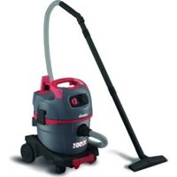
AV P-15 18V - Vacuum Cleaner Starmix - Free user manual and instructions
Find the device manual for free AV P-15 18V Starmix in PDF.

| Product type | Ash vacuum cleaner |
| Brand | Starmix |
| Model | AV P-15 18V |
| Nominal voltage | 18 V (battery) |
| Nominal power | 350 W |
| Max vacuum (motor/appliance) | 11 / 10 kPa |
| Max airflow (motor/appliance) | 2040 / 1200 l/min |
| Container capacity | 15 liters |
| Weight | 2.8 kg |
| Sound pressure level | 70.5 dB(A) |
| Sound power level | 79 dB(A) |
| Vibration emission value | < 2.5 m/s² |
| Operating temperature | -20 °C to 45 °C |
| Storage temperature | +10 °C to 45 °C |
| Protection class | III |
| Compatible battery | CAS 18 V (Li-ion, e.g. 2.0 / 5.2 / 10.0 Ah) |
| Main filter | Washable pleated filter |
| Prefilter (optional) | Heat resistant |
| Filter cleaning system | Integrated shaker |
| Intended use | Suction of cold ashes (<40°C) and coarse dirt |
| Safety | Motor thermal protection |
| Included accessories | Aluminum nozzle, metal hose, crevice tool |
| Warranty | 2 years |
| Repairability | Authorized after-sales service |
Frequently Asked Questions - AV P-15 18V Starmix
User questions about AV P-15 18V Starmix
0 question about this device. Answer the ones you know or ask your own.
Ask a new question about this device
Download the instructions for your Vacuum Cleaner in PDF format for free! Find your manual AV P-15 18V - Starmix and take your electronic device back in hand. On this page are published all the documents necessary for the use of your device. AV P-15 18V by Starmix.
USER MANUAL AV P-15 18V Starmix
natural_image
White industrial vacuum cleaner with red handle and gray body, no visible text or symbols on device bodyde Bedienungsanleitung 2 fi Käyttöohje 82
en operating instructions 12 no Bruksanvisning 92
fr Notice d'utilisation 22 da Brugsanvisningen 102
nl Gebruiksaanwijzing 32 pl Instrukcja obsługi 112
it Istruzioni per l'uso 42 cs Návod k obsluze 122
es Manual de instrucciones 52 hu Használati utasítás 132
pt Manual de instruções 62 ru Руководство по эксплуатации 142
se Bruksanvisning 72
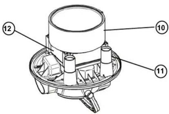
Abb.4
4.2 SAUGEN - EINSETZEN DES SCHLAUCHS
Abb.5
natural_image
Technical line drawing of a mechanical device with directional arrows indicating motion (no text or symbols)Abb.6
Abb.7A
4.3.1 EINSCHALTEN DES GERÄTS (AKKU)
Abb.10
Model(s): AV P-15 18V, AV P-20 18V, AV P-25 18V
DC 18V 350W Class III
EN IEC 55014-1:2021, EN IEC 55014-2:2021, IEC 61000-4-2:2019, EN 61000-4-3:2020
EN IEC 63000:2018
Congratulations on the purchase of your new ash vacuum cleaner.
Prior to using the appliance for the first time, be sure to read this document through and keep it ready to read instructions of use.
PURPOSE AND INTENDED USE
This vacuum cleaner is designed, developed and rigorously tested to function efficiently and safely when properly maintained and used in accordance with the following instructions.
The ash vacuum cleaner is intended for indoor household use only and not for commercial purposes.
The device is suitable for picking up:
- cold ashes from fireplaces, chimneys, ovens, ashtrays and similar places where ashes accumulate.
- Coarse dirt of all types, such as sand or rubble.
CAUTION: READ AND FOLLOW ALL SAFETY INSTRUCTIONS.
1. IMPORTANT SAFETY INSTRUCTIONS
- Warning and information plates on the machine provide important directions for safe operation.
- Apart from the notes contained herein the general safety provisions and rules for the prevention of accidents of the legislator must be observed.
1.1 HAZARDS LEVELS:

DANGER

Pointer to immediate danger, which leads to severe injuries or death.
WARNING

Pointer to a possibly dangerous situation, which can lead to severe injuries or death.
CAUTION

Pointer to a possibly dangerous situation, which can lead to minor injuries.
ATTENTION
Pointer to a possibly dangerous situation, which can lead to property damage.
1.2 ELECTRICAL COMPONENTS

DANGER
Risk of electric shock!
- Repair work and work on the electrical components
may only be performed by an authorised customer service. - Do not use scouring agents, glass or multi-purpose cleaners!
- Do not immerse the appliance into water!
1.3 SAFE HANDLING

DANGER
- Keep packaging films away from children, there is a risk of suffocation!
WARNING
- This device must not be used by children or persons with restricted physical, sensory or mental abilities or those lacking in experience and/or lacking in knowledge.
- Children must not play with this appliance.
- Supervise children to prevent them from playing with the appliance.
- Cleaning and user maintenance shall not be made by children without supervision.
- This appliance can be used by children aged from 8 years and above and persons with reduced physical, sensory or mental capabilities or lack of experience and knowledge, if they have been given supervision or instruction concerning use of the appliance in a safe way and under the hazards involved.

CAUTION
- In case of extended breaks, switch the appliance off at the main switch / appliance switch or pull the mains plug / remove the battery.
- Never leave the appliance unattended as long as it is in operation.
- Switch off the appliance after every use and prior to every cleaning / maintenance and pull the mains plug / remove the battery.

ATTENTION
- Never vacuum without inserting a flat fold filter and the optional associated frame, otherwise the device can be damaged.
- Protect the appliance from extreme weather conditions, moisture and heat.
1.4 OTHER RISK

DANGER
Risk of explosion!
- Certain materials may produce explosive vapors or mixtures when agitated by the suction air!
-
Never vacuum up the following materials:
-
Explosive or combustible gases, liquids and dust particles (reactive dust particles)
○ Reactive metal dust particles (such as aluminum, magnesium, zinc) in combination with highly alkaline or acidic detergents. -
Hot, burning or smoldering objects with temperatures greater than 40°C. Temperatures above 40°C represent a fire hazard.
-
Not suitable to separate health-hazardous dust (dust classes L, M, H).
- The appliance may not be operated in explosive atmospheres. In addition, these substances may cause the appliance materials to corrode.

WARNING
Risk of fire!
- Do not pick up hot, glowing or burning ash. Pick up only cold ash.
- The dust container must be emptied and cleaned before and after each use.
- Do not use dust collection bags made of paper or bags made of similarly combustible materials.
- Do not use customary vacuum cleaners to vacuum ashes.
- Do not store the ash vacuum on combustible or polymeric surfaces such as carpet or vinyl tiles.
- Only ashes from permissible fuels (e.g., natural wood, wooden briquets, wood pellets, lignite and hard coal) must be vacuumed.
- Do not vacuum up soot.
- Vacuuming material which appears to have cooled down from the outside may still be very hot inside. Hot ash particles may ignite again in the air flow.
- Stir up the ashes with a metal object to check whether the ashes are still hot.
- Please make sure that the oven is cold before you vacuum clean ovens.
- Wait until the ashes have cooled down before you begin with the cleaning. We do not recommend extinguishing the fire rapidly with water. The chimney material will not withstand the quick temperature changes and may crack.
Continuously check hoses and vacuum cleaner for heat while vacuuming ashes. If you notice a temperature rise, switch off the vacuum cleaner immediately. Pull out the mains plug / the main battery. Remove the vacuuming material from the ash and dry vacuum cleaner. Allow device to cool down outside under supervision.

Danger from burning battery!
- Overheating of the battery and short circuits can lead to the battery catching fire and exploding.
- Protect the battery pack from heat, e.g. also from constant exposure to sunlight and fire.
- When a battery is not in use, keep it away from other metal objects such as paper clips, coins, keys, nails, screws or other small metal objects. These could establish a conductive connection between the contacts.
- Do not transport battery packs in carrying bags with mixed contents.
- NEVER POUR WATER ON A BURNING LI-ION BATTERY! Always use a fire extinguisher (fire class D).
-
Do not inhale fumes from a burning battery. Seek medical attention if neccesary.
-
Do not charge the battery at ambient temperatures below 5 °C or above 45 °C The longest life and best performance of the battery pack is achieved when it is charged at an air temperature of about 20 °C.
- If the battery pack becomes too hot while charging, disconnect the mains plug and switch off the device immediately.
- Do not short-circuit the battery contacts.
- Clean the batteries and battery compartment regularly.
- Replace defective batteries.
- Do not open the batteries.
- If the battery is leaking, do not touch the leaking material.

Danger due to lightning strike!
- Do not use the vacuum cleaner outdoors during thunderstorms.

DANGER
Risk of electric shock!
- The voltage in the type plate must match the battery voltage.
- Switch off the vacuum cleaner after each use and before any maintenance.
- Never open the vacuum cleaner outdoors in rain or storms.
- Store the vacuum cleaner indoors in a dry place and protected from frost.
- Only use original batteries (CAS battery 18 V). Battery packs with different capacities. Buy battery packs only with voltage suitable for your power tool. For example:
Order no.: 461205 18 V 2.0 Ah (Li-Ion)
Order no.: 459745 18 V 5.2 Ah (Li-Ion)
Order no.: 457031 18 V 10.0 Ah (LiHD)
- Remove battery when not in use.
- Remove the battery before servicing or opening the vacuum cleaner.
- Switch off the vacuum cleaner before changing the battery.
- Do not touch the battery with wet hands.
- If foam or liquid is leaking out, switch off the vacuum cleaner immediately. Empty the container and pleated filter cassette.
- Always keep the inside of the cover dry.
- Do not touch the contacts in the battery compartment with hands or other objects.
- Do not place any objects in the battery compartment.
- Before use, check that the battery is securely in place.
- Clean the battery contacts regularly.
- Ensure charge balance.
- Rechargeable batteries are to be removed from the appliance before being charged.
- Batteries are to be inserted with the correct polarity.
- Exhausted batteries are to be removed from the appliance and safely disposed of.
- If the appliance is to be stored unused for a long period, the batteries are removed.
- The supply terminals are not to be short-circuited.

WARNING
Risk of injury!
- Do not vacuum in the vicinity of the head when using the nozzle and suction pipe.

CAUTION
- In order to prevent accidents or injuries, mind the weight of the appliance during transport (see technical data).
1.5 STABILITY

CAUTION
- Create stability for the appliance prior to any work on or with the appliance to prevent accidents or damage.
1.6 SAFETY DEVICES

CAUTION
- Safety installations serve the protection of the user and may not be modified or bypassed.
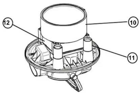
2. OVERVIEW
Fig.1
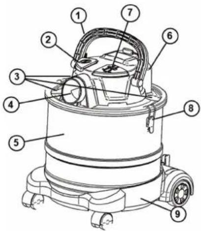
- Handle
- On/Off Button
- Nozzle holder
- Inlet
- Tank
- Battery case
- Head
- Buckle
- Wheel chassis (optional)
- Pre-filter (heat-resistant) (optional)
- Protection foot
- Main Filter
- Aluminum nozzle
- Metal Hose
- Brush nozzle (optional)
- Crevice nozzle (optional)
- Disposal bag (optional)
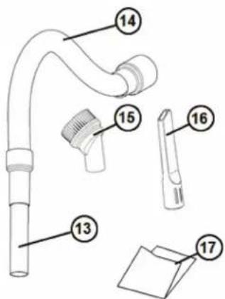
Some of these accessories are packed inside the tank
| COMCE15DC-CAS | COMCE20DC-CAS | COMCE25DC-CAS | |
| Model name | AV P-15 18V | AV P-20 18V | AV P-25 18V |
| Voltage / Freugency | 18V | 18V | 18V |
| Nominal Power | 350W | 350W | 350W |
| Max. Vacuum (motor/machine) | 11/10kPa | 11/10kPa | 11/10kPa |
| Ambient temperature | -20 °C ... 45 °C | -20 °C ... 45 °C | -20 °C ... 45 °C |
| Storage temperature | +10 °C ... 45 °C | +10 °C ... 45 °C | +10 °C ... 45 °C |
| Max. Flow (motor/machine) | 2040/1200l/min | 2040/1200l/min | 2040/1200l/min |
| Protection Class | III | III | III |
| Weight | 2,8 kg | 3,1 kg | 3,3 kg |
| Tank size | 15l | 20l | 25l |
| Sound pressure level LpA / KpA | 70,5 / 3 dB(A) | 70,5 / 3 dB(A) | 70,5 / 3 dB(A) |
| Sound power level LWA / KWA | 79 / 3 dB(A) | 79 / 3 dB(A) | 79 / 3 dB(A) |
| Vibration emission value (ah) | < 2.5 m/s2 | < 2.5 m/s2 | < 2.5 m/s2 |
3. FIRST TIME SET UP INSTRUCTIONS
Read chapter 1 – IMPORTANT SAFETY INSTRUCTIONS of this manual thoroughly before setting up and using this vacuum cleaner.
3.1 ACCESSORIES
The nozzles and accessories for the machine are during shipping stored in tank. To open the tank, disengage the buckles (A) and take off the head (B). Take out the items (C) and put on the head again. Secure the head with the buckles
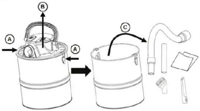
Fig.3
4. USING THE VACUUM CLEANER
Read chapter 1 – IMPORTANT SAFETY INSTRUCTIONS of this manual thoroughly before setting up and using this vacuum cleaner.
4.1 WORKING WITH DISPOSAL BAGS
To empty the tank for debris/dust in a dustless way a disposal bags can beneficially be used. Any plastic bag that fits can be used.
Add the bag into the tank (A). Fix the bag over the edge of the tank (B). Make sure the two holders (C) inside the tank goes through the bag securing same pressure inside as outside of the bag. If not, the bag will be sucked into the filter and suction will be gone.
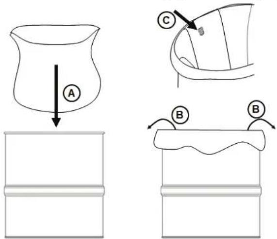
Fig.4
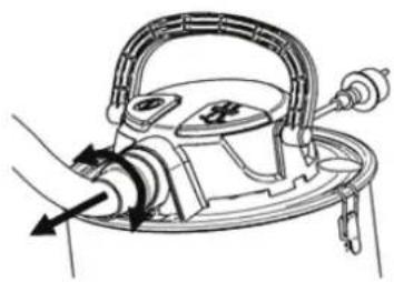
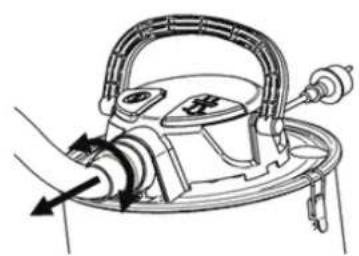
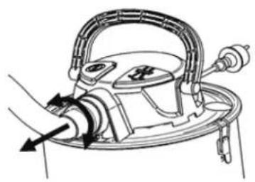
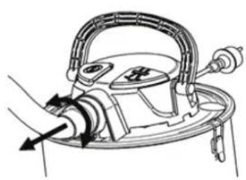
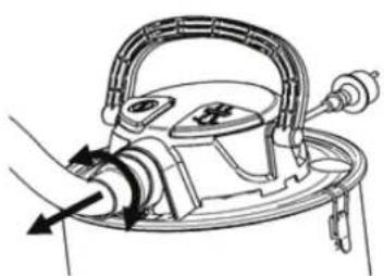
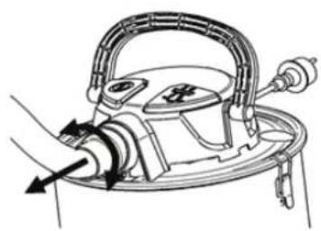
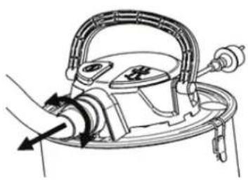
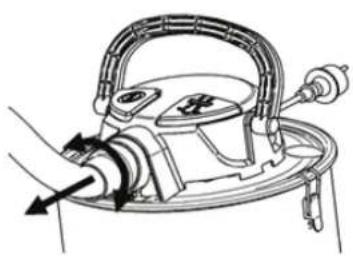
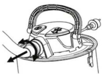
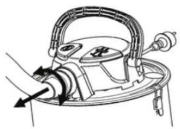
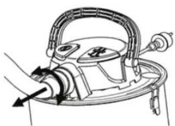
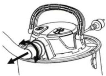
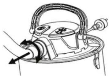
4.2 VACUMING - INSERTING THE HOSE
To vacuum insert the nozzle (A) into the suction hose cuff as on Fig. 5. Insert the hose with the cuff in the inlet of the vacuum cleaner (B).
To remove the hose twist and pull out as seen on Fig. 6
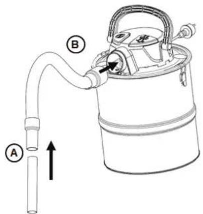
Fig.5
Fig.6
natural_image
Technical line drawing of a mechanical device with directional arrows indicating motion (no text or symbols)4.3 TURNING THE MACHINE ON
The machine is turned on/off by pressing the start/stop button (A).
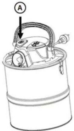
Fig.7A
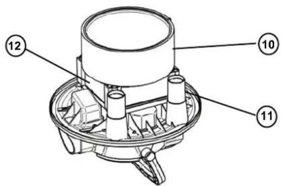
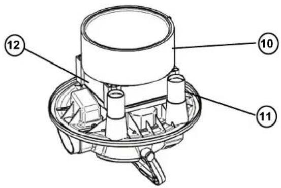
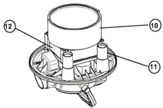
4.3.1 TURNING THE MACHINE ON (BATTERY)
Push a suitable battery pack (only CAS battery 18 V) into the receptacle on the motor head until it audibly engages.
Then switch the vacuum cleaner on/off as described in chapter 4.3.
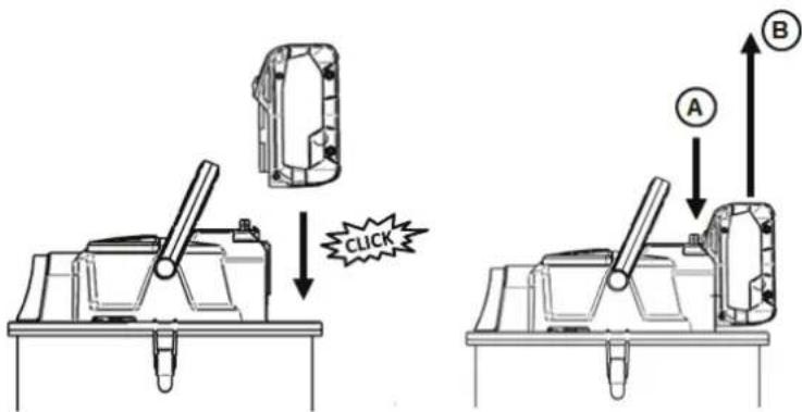
Fig.7B
4.3.2 REMOVING THE BATTERY
To remove the battery, press button (A) and pull the battery pack upwards (B). Remove the battery from the device after use!
4.4 EMPTYING THE TANK USING DISPOSAL BAG
To empty the tank, take off the head. If using a disposal bag carefully connect the bag and close it with cable tie or similar (A). Take our carefully the disposal bag (B)
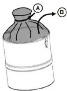
Fig.8
4.5 FILTER CLEANING SYSTEM

The vacuum cleaner is equipped with a built-in filter cleaning system. Fine dust and ash will easily clog the filter. In order to clean the filter and restore suction performance do as on Fig. 9. Put the nozzle into the holder (A) thereby closing for suction. Turn the machine on (B). Wait few seconds until motor has full speed and vacuum is highest. Push the filter cleaning button 5 times (C).
If suction is not restored the filter maybe damaged and need to be replaced. See next chapter for more information
Fig.9
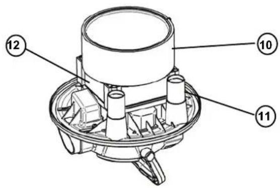
4.6 REMOVING AND CLEANING FILTER
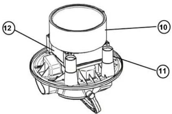
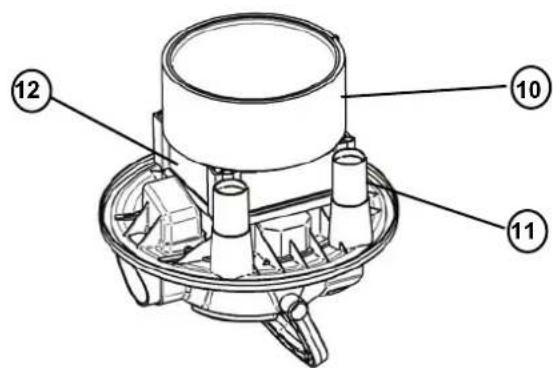
Take off the head and put it upside down (Fig. 10)
If the vacuum cleaner is equipped with a pre-filter, carefully pull it off (A), clean it (B), let it dry (C) and put everything back together when it is dry (D). Check that the filter is properly seated.
To change or clean the main filter, loosen the 4 screws and remove the parts (A). If the filter is damaged, replace it with a new one and assemble it in the same way. Be careful not to overtighten the screws.
If the filter is dirty, wash it under cold water (B) and let it dry (C). Replace the filter after it has dried.
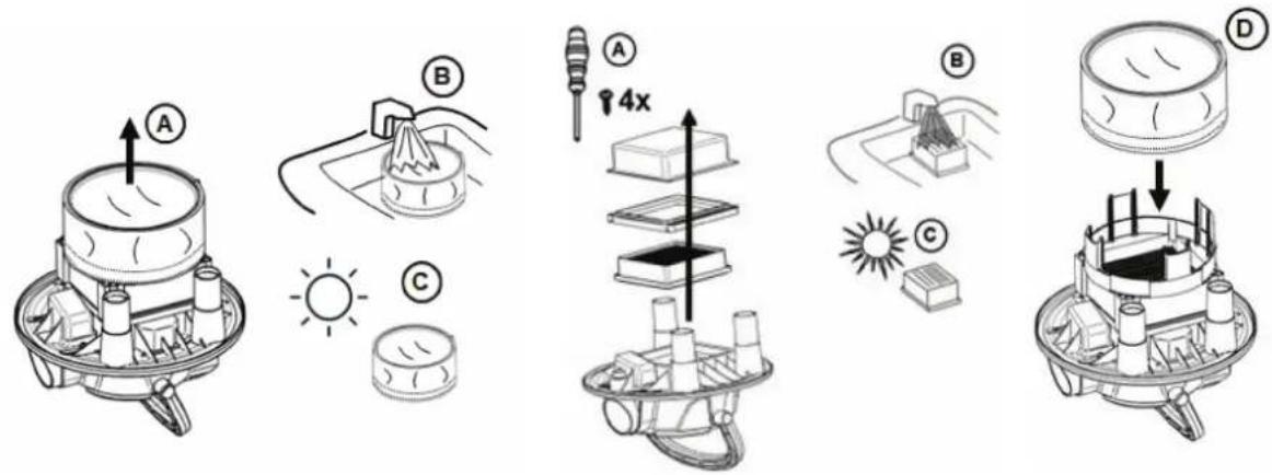
Fig.10
This vacuum cleaner can be equipped with a built-in thermal overload protector to protect the motor from high temperatures. This can occur under heavy use. If the motor temperature shuts off during operation, turn the switch off and allow the motor to cool for 15-30 minutes. Turn switch on and resume operation.
5. TROUBLE SHOOTING
Repair or service of electrical components such as cord or motor, must only be carried out by an authorized service center.
| Vacuum does not start: | - Check to see that the plug is correctly inserted in the electrical outlet and that there is power at receptacle.- A circuit breaker may have tripped. Check the circuit breaker box.- The cord or plug may be damaged. Call the Customer Service Department to get the nearest authorized service center.- Battery pack empty, change/replace battery pack.- check battery fit. |
| Motor stops: | - A thermal overload protector will shut off the motor if the motor temperature is too high. If this occurs, turn the switch off. Wait 15-30 minutes for the motor to cool. Turn switch on and resume operation. |
| Suction power is reduced: | - The tank may be full and needs to be emptied. See Fig. 8- The hose and nozzle may be clogged and need to be cleaned.- Any of the above may be damaged and need to be replaced.- The filter may be clogged. Use the Filter Cleaning System (see Fig 9), to clean the filter.- Replace the filter or make sure the filter is installed properly.- The hose connection is loose and need to be tightened. |
| Static shocks: | - If the environment is too dry, add moisture to air. If possible, use a humidifier.- In case the relative humidity of air is low, please note that this situation will not have any effect on use of the vacuum cleaner. |
6. WARRANTY
Warranty covers:
This vacuum cleaner is warranted for 2 years. This warranty includes spare parts and labor costs and covers manufacturing and material defects that may occur during normal use. This warranty does not include normal wear and tear.
Service under this warranty will only be performed with proof that the defect occurred within the warranty period and that the vacuum cleaner was purchased as a new product. Proof would be a cash register receipt with date and product type.
Warranty does not cover:
- Normal wear and tear of accessories and filters.
- Defects or damage occurring as a direct or indirect result of incorrect use
- Abuse due to failure to follow instructions in the user manual.
- Incorrect or poor configuration, i.e. setting up or improper connection, fire-damage, fire, lightning strike or unusual voltage fluctuations or any other electrical disturbances. Electrical disturbances include a defective circuit breaker or defective electrical installations on the supply grid.
Warranty becomes void:
- If a failure is caused by the use of non-original filters.
- If the model, item or any identity/serial number is removed from the vacuum cleaner.
- If the vacuum cleaner has been repaired by a non-authorized dealer.
- If the machine has been used for commercial purpose.

WARNING
If any of the motor housing parts should become detached or broken, operations should be discontinued immediately to avoid personal injury. Repairs should be made before reuse.
Note: FOR TECHNICAL ASSISTANCE, CONTACT OUR CUSTOMER SERVICE DEPARTMENT.

Old Equipment contains valuable materials which are designed for re-processing. The vacuum cleaners must not be thrown away in the normal household waste, but should be disposed of at a suitable proper collection system, e.g. via your communal disposal location.
Batteries do not belong in household waste. Batteries contain valuable materials such as zinc, iron, aluminium, lithium and silver. Some of the possible ingredients, such as mercury, cadmium and lead, are heavy metals which can be harmful to the environment and health if they are not disposed of properly. If the disposable and rechargeable batteries are disposed of with the household waste, harmful substances could be released into the environment. In addition, valuable raw materials will be lost. Furthermore, batteries can contain substances that can cause irritation or allergies or are highly reactive. Dispose of used disposable and rechargeable batteries properly in the collection boxes at retailers or at municipal collection points.
CE DECLARATION OF CONFORMITY
We:
ELECRTROSTAR GmbH
Hans-Zinser-Str. 1-3
73061 Ebersbach/Fils
Germany
declare under our responsibility that the product
Vacuum Cleaner
COMCE15DC-CAS, COMCE20DC-CAS, COMCE25DC-CAS
Model(s):
AV P-15 18V, AV P-20 18V, AV P-25 18V
DC 18V 350W Class III
to which this declaration relates is in conformity with the following standards or other normative document(s):
Applied harmonized standards
EN 60335-1:2012 + A11:2014 + A13:2017 + A1:2019 + A14:2019 + A2:2019 + A15:2021
EN 60335-2-2:2010 + A11:2012 + A1:2013
EN 62233:2008
EN IEC 55014-1:2021, EN IEC 55014-2:2021, IEC 61000-4-2:2019, EN 61000-4-3:2020
EN IEC 63000:2018
Applied national standards and technical specification
IEC 60335-2-2:2009, AMD1:2012, AMD2
IEC 60335-1:2010 + AMD1:2013 + AMD2:2016
following the provisions of the Directives: 2014/30/EU (Electromagnetic capability EMC), 2011/65/EC (Directive RoHS II), 2006/42/EC (Machinery directive)
14.11.2022
Canton Srenn
Person authorised to compile the technical file
CHÈRE CLIENTE, CHER CLIENT
4. UTILISATION DE L'ASPIRATEUR
4.2 ASPIRER - UTILISER LE TUYAU
Fig. 5 Fig. 6
natural_image
Technical line drawing of a mechanical device with no visible text or symbols4.3 MISE EN SERVICE DE L'APPAREIL
Fig. 7A
4.3.1 MISE EN SERVICE DE L'APPAREIL (BATTERIE)
Fig. 8
4.5 DISPOSITIF DE NETTOYAGE DE FILTRE
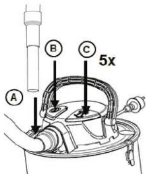
Fig. 10
DÉCLARATION CE DE CONFORMITÉ
Nous :
ELECRTROSTAR GmbH
Hans-Zinser-Str. 1-3
73061 Ebersbach/Fils
Germany
Model(s): AV P-15 18V, AV P-20 18V, AV P-25 18V
DC 18V 350W Classe III
EN IEC 55014-1:2021, EN IEC 55014-2:2021, IEC 61000-4-2:2019, EN 61000-4-3:2020
EN IEC 63000:2018
Fig.1
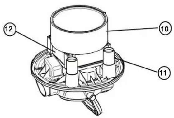

Fig.3
4. GEBRUIK VAN DE STOFZUIGER
4.1 WERKEN MET AFVALZAKKEN
Fig.5 Fig.6
natural_image
Technical line drawing of a mechanical device with directional arrows indicating motion (no text or symbols)4.3 INSCHAKELEN VAN HET APPARAAT
Fig.7B
Fig.10
5. PROBLEEMOPLOSSING
Model(s): AV P-15 18V, AV P-20 18V, AV P-25 18V
DC 18V 350W Class III
EN IEC 55014-1:2021, EN IEC 55014-2:2021, IEC 61000-4-2:2019, EN 61000-4-3:2020
EN IEC 63000:2018
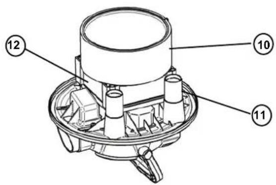
Fig. 1
Fig. 3
4. UTILIZZO DELL'ASPIRAPOLVERE
Fig. 4
4.2 ASPIRAZIONE - INSERIMENTO DEL TUBO FLESSIBILE
Fig. 5
Fig. 6
natural_image
Technical line drawing of a mechanical device with directional arrows indicating motion (no text or symbols)4.3 ACCENSIONE DELL'APPARECCHIO
natural_image
Diagram of a cylindrical container with internal components and a labeled section A (no text or symbols beyond label)Fig. 7A
4.3.1 ACCENSIONE DELL'APPARECCHIO (BATTERIA)
Fig. 7B
Fig. 10
DC 18V 350W Class III
EN IEC 55014-1:2021, EN IEC 55014-2:2021, IEC 61000-4-2:2019, EN 61000-4-3:2020
EN IEC 63000:2018
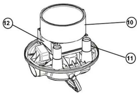
Fig. 1
Fig. 4
Fig. 5 Fig. 6
natural_image
Technical line drawing of a mechanical device with no visible text or symbols4.3 ENCENDER EL APARATO
natural_image
Diagram of a cylindrical container with internal components and a labeled section A (no text or symbols beyond label)Fig. 7A
4.3.1 ENCENDER EL APARATO (BATERÍA)
Fig. 7B
Fig. 10
Modelo (s): AV P-15 18V, AV P-20 18V, AV P-25 18V
DC 18V 350W Class III
EN IEC 55014-1:2021, EN IEC 55014-2:2021, IEC 61000-4-2:2019, EN 61000-4-3:2020
EN IEC 63000:2018

Fig. 3:
Fig. 4:
Fig.5 Fig.6

natural_image
Technical line drawing of a mechanical device with no visible text or symbols4.3 LIGAR O APARELHO
natural_image
Line drawing of a bucket with a handle and labeled component (no text or symbols)Fig. 7A
4.3.1 LIGAR O APARELHO (BATERIA)
Fig. 8:
4.5 SISTEMA DE LIMPEZA DI FILTRO
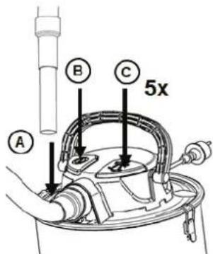
Fig. 10
Modelo(s): AV P-15 18V, AV P-20 18V, AV P-25 18V
DC 18V 350W Classe III
EN IEC 55014-1:2021, EN IEC 55014-2:2021, IEC 61000-4-2:2019, EN 61000-4-3:2020
EN IEC 63000:2018
4. ANVÄNDNING AV DAMMSUGAREN
4.2 DAMMSUGNING - ISÄTTNING AV SLANGEN
Illustration 5
natural_image
Technical line drawing of a mechanical device with no visible text or symbolsIllustration 6
4.3 PÅSLAGNING AV ENHETEN
natural_image
Line drawing of a bucket with labeled parts (A and an arrow), no text or symbols presentIllustration 7A
4.3.1 PÅSLAGNING AV ENHETEN (BATTERI)
Illustration 10
DC 18V 350W Class III
EN IEC 55014-1:2021, EN IEC 55014-2:2021, IEC 61000-4-2:2019, EN 61000-4-3:2020
EN IEC 63000:2018
Kuva 3
4. IMURIN KÄYTTÖ
Kuva 4
4.2 IMUROINTI - LETKUN ASETTAMINEN
Kuva 5
Kuva 6
natural_image
Technical line drawing of a mechanical device with directional arrows indicating motion (no text or symbols)4.3 LAITTEEN KÄYNNISTÄMINEN
natural_image
Diagram of a cylindrical container with internal components and a labeled section A (no text or symbols beyond label)Kuva 7A
4.3.1 LAITTEEN KÄYNNISTÄMINEN (AKKU)
Kuva 7B
4.3.2 PARISTON POISTO
Kuva 10
DC 18V 350W Class III
EN IEC 55014-1:2021, EN IEC 55014-2:2021, IEC 61000-4-2:2019, EN 61000-4-3:2020
EN IEC 63000:2018

Abb.3
4. BRUK AV ST∅VSUGEREN
Les kapittel 1 - VIKTIGE SIKKERHETSANVISNINGER i denne bruksanvisningen grundig før støvsugeren monteres og benyttes.
4.1 ARBEIDER MED S∅PPELPOSER

natural_image
Technical line drawing of a mechanical device with directional arrows indicating movement or force (no text or symbols)Fig.5 Fig.6
4.3 INNKOBLING AV APPARATET
natural_image
Diagram of a cylindrical container with internal components and a labeled arrow (A), no readable text or symbols present.Abb.7A
4.3.1 INNKOBLING AV APPARATET (BATTERI)
Skyv et egnet batteri (kun CAS-batteri 18 V) inn i holderen på motorhodet, til det hørbart smekker på plass.
Slå deretter på/av støvsugeren som beskrevet i kapittel 4.3.
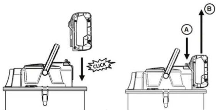
Fig.7B
4.3.2 FJERN BATTERIET
4.4 T∅MMING AV BEHOLDEREN MED S∅PPELPOSE
Abb.10
DC 18V 350W Class III
EN IEC 55014-1:2021, EN IEC 55014-2:2021, IEC 61000-4-2:2019, EN 61000-4-3:2020
EN IEC 63000:2018
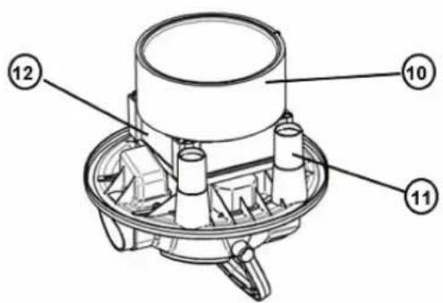
Fig.3
4. BRUG AF ST∅VSUGEREN
Fig.4
4.2 SUGNING - INDSÆTTELSE AF SLANGEN
Fig.5 Fig.6
natural_image
Technical line drawing of a mechanical device with directional arrows indicating movement (no text or symbols)4.3 TÆNDING AF APPARATET
natural_image
Diagram of a cylindrical container with internal components and a labeled section A (no text or symbols beyond label)Fig.7A
4.3.1 TÆNDING AF APPARATET (BATTERI UDGAVE)
4.4 T∅MNING AF BEHOLDEREN MED EN ST∅VPOSE
Fig.10
Model(s): AV P-15 18V, AV P-20 18V, AV P-25 18V
DC 18V 350W Class III
som denne erklæring henviser til, er i overensstemmelse med følgende standarder eller andre normative dokumenter:
EN IEC 55014-1:2021, EN IEC 55014-2:2021, IEC 61000-4-2:2019, EN 61000-4-3:2020
EN IEC 63000:2018
Rys.3
4. UŻYWANIE ODKURZACZA
Rys. 4
4.2 ODKURZANIE - ZAKŁADANIE WEŻA
Rys. 5
Rys. 6
natural_image
Technical line drawing of a mechanical device with no visible text or symbols4.3 WŁĄCZANIE URZĄDZENIA
Rys. 7B
4.3.2 WYJMOWANIE AKUMULATORA
Rys. 8
4.5 SYSTEM CZYSZCZENIA FILTRA

Rys. 10
EN IEC 55014-1:2021, EN IEC 55014-2:2021, IEC 61000-4-2:2019, EN 61000-4-3:2020
EN IEC 63000:2018
1.1 STUPNĚ OHROŽENÍ:

NEBEZPEČÍ
Obr. 3
4. POUŽIVÁNÍ VYSAVAČE
Obr. 4
4.2 VYSÁVÁNÍ - NASAZENÍ HADICE
Obr. 5
Obr. 6
natural_image
Technical line drawing of a mechanical device with no visible text or symbols4.3 ZAPNUTÍ PŘÍSTROJE
Obr. 10
DC 18 V, 350 W, Class III,
EN IEC 55014-1:2021, EN IEC 55014-2:2021, IEC 61000-4-2:2019, EN 61000-4-3:2020
EN IEC 63000:2018
- ábra
4. A PORSZÍVÓ HASZNÁLATA
4.2 PORSZÍVÓZÁS - A CSŐ BEHELYEZÉSE
- ábra
- ábra
natural_image
Technical line drawing of a mechanical device with no visible text or symbols4.3 A KÉSZÜLÉK BEKAPCSOLÁSA
7B ábra
- ábra
DC 18V 350W Class III
EN IEC 55014-1:2021, EN IEC 55014-2:2021, IEC 61000-4-2:2019, EN 61000-4-3:2020
EN IEC 63000:2018
Рис.5 Рис.6
natural_image
Technical line drawing of a mechanical device with directional arrows indicating motion (no text or symbols)natural_image
Diagram of a bucket with labeled component A, showing internal parts and handle (no text or symbols beyond label)Рис.7А
Рис.10
DC 18V 350W Class III
EN IEC 55014-1:2021, EN IEC 55014-2:2021, IEC 61000-4-2:2019, EN 61000-4-3:2020
EN IEC 63000:2018
- SAUGEN - EINSETZEN DES SCHLAUCHS
- EINSCHALTEN DES GERÄTS (AKKU)
- PURPOSE AND INTENDED USE
- IMPORTANT SAFETY INSTRUCTIONS
- HAZARDS LEVELS:
- DANGER
- WARNING
- CAUTION
- ATTENTION
- ELECTRICAL COMPONENTS
- Risk of electric shock!
- SAFE HANDLING
- OTHER RISK
- Risk of explosion!
- Risk of fire!
- Danger from burning battery!
- Danger due to lightning strike!
- Risk of injury!
- STABILITY
- SAFETY DEVICES
- OVERVIEW
- FIRST TIME SET UP INSTRUCTIONS
- ACCESSORIES
- USING THE VACUUM CLEANER
- WORKING WITH DISPOSAL BAGS
- VACUMING - INSERTING THE HOSE
- TURNING THE MACHINE ON
- TURNING THE MACHINE ON (BATTERY)
- REMOVING THE BATTERY
- EMPTYING THE TANK USING DISPOSAL BAG
- FILTER CLEANING SYSTEM
- REMOVING AND CLEANING FILTER
- TROUBLE SHOOTING
- WARRANTY
- Warranty covers:
- Warranty does not cover:
- Warranty becomes void:
- CE DECLARATION OF CONFORMITY
- DC 18V 350W Class III
- CHÈRE CLIENTE, CHER CLIENT
- UTILISATION DE L'ASPIRATEUR
- ASPIRER - UTILISER LE TUYAU
- MISE EN SERVICE DE L'APPAREIL
- MISE EN SERVICE DE L'APPAREIL (BATTERIE)
- DISPOSITIF DE NETTOYAGE DE FILTRE
- DÉCLARATION CE DE CONFORMITÉ
- GEBRUIK VAN DE STOFZUIGER
- WERKEN MET AFVALZAKKEN
- INSCHAKELEN VAN HET APPARAAT
- PROBLEEMOPLOSSING
- UTILIZZO DELL'ASPIRAPOLVERE
- ASPIRAZIONE - INSERIMENTO DEL TUBO FLESSIBILE
- ACCENSIONE DELL'APPARECCHIO
- ACCENSIONE DELL'APPARECCHIO (BATTERIA)
- ENCENDER EL APARATO
- ENCENDER EL APARATO (BATERÍA)
- LIGAR O APARELHO
- LIGAR O APARELHO (BATERIA)
- SISTEMA DE LIMPEZA DI FILTRO
- DC 18V 350W Classe III
- ANVÄNDNING AV DAMMSUGAREN
- DAMMSUGNING - ISÄTTNING AV SLANGEN
- PÅSLAGNING AV ENHETEN
- PÅSLAGNING AV ENHETEN (BATTERI)
- IMURIN KÄYTTÖ
- IMUROINTI - LETKUN ASETTAMINEN
- LAITTEEN KÄYNNISTÄMINEN
- LAITTEEN KÄYNNISTÄMINEN (AKKU)
- PARISTON POISTO
- BRUK AV ST∅VSUGEREN
- ARBEIDER MED S∅PPELPOSER
- INNKOBLING AV APPARATET
- INNKOBLING AV APPARATET (BATTERI)
- FJERN BATTERIET
- T∅MMING AV BEHOLDEREN MED S∅PPELPOSE
- BRUG AF ST∅VSUGEREN
- SUGNING - INDSÆTTELSE AF SLANGEN
- TÆNDING AF APPARATET
- TÆNDING AF APPARATET (BATTERI UDGAVE)
- T∅MNING AF BEHOLDEREN MED EN ST∅VPOSE
- UŻYWANIE ODKURZACZA
- ODKURZANIE - ZAKŁADANIE WEŻA
- WŁĄCZANIE URZĄDZENIA
- WYJMOWANIE AKUMULATORA
- SYSTEM CZYSZCZENIA FILTRA
- STUPNĚ OHROŽENÍ:
- NEBEZPEČÍ
- POUŽIVÁNÍ VYSAVAČE
- VYSÁVÁNÍ - NASAZENÍ HADICE
- ZAPNUTÍ PŘÍSTROJE
- A PORSZÍVÓ HASZNÁLATA
- PORSZÍVÓZÁS - A CSŐ BEHELYEZÉSE
- A KÉSZÜLÉK BEKAPCSOLÁSA
Brand : Starmix
Model : AV P-15 18V
Category : Vacuum Cleaner