BC-510 PRO - Brush cutter SABO - Free user manual and instructions
Find the device manual for free BC-510 PRO SABO in PDF.

User questions about BC-510 PRO SABO
0 question about this device. Answer the ones you know or ask your own.
Ask a new question about this device
Download the instructions for your Brush cutter in PDF format for free! Find your manual BC-510 PRO - SABO and take your electronic device back in hand. On this page are published all the documents necessary for the use of your device. BC-510 PRO by SABO.
USER MANUAL BC-510 PRO SABO
natural_image
Technical line drawing of a mechanical device with articulated arms and housing (no text or symbols)text_image
FIG.3 H D E A F B G C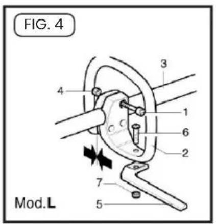
text_image
FIG. 4 Mod.L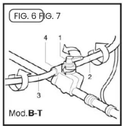
text_image
FIG. 6 FIG. 7 Mod.B-T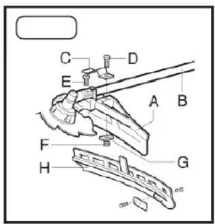
text_image
Technical diagram of a mechanical assembly with labeled parts A through H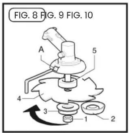
text_image
FIG. 8 FIG. 9 FIG. 10 A 5 4 3 1 2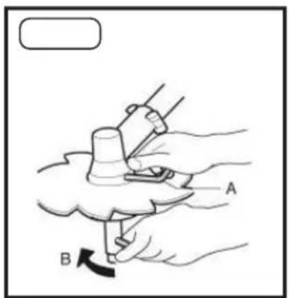
text_image
Diagram showing a hand holding a tool with labeled parts A and B, indicating a mechanical or diagnostic procedure.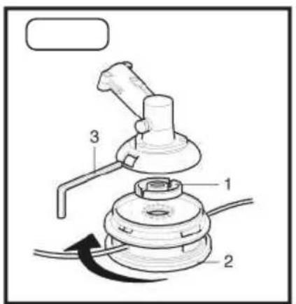
text_image
Technical diagram of a mechanical device with labeled parts and directional arrow indicating rotation or movement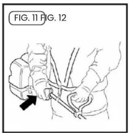
text_image
FIG. 11 FIG. 12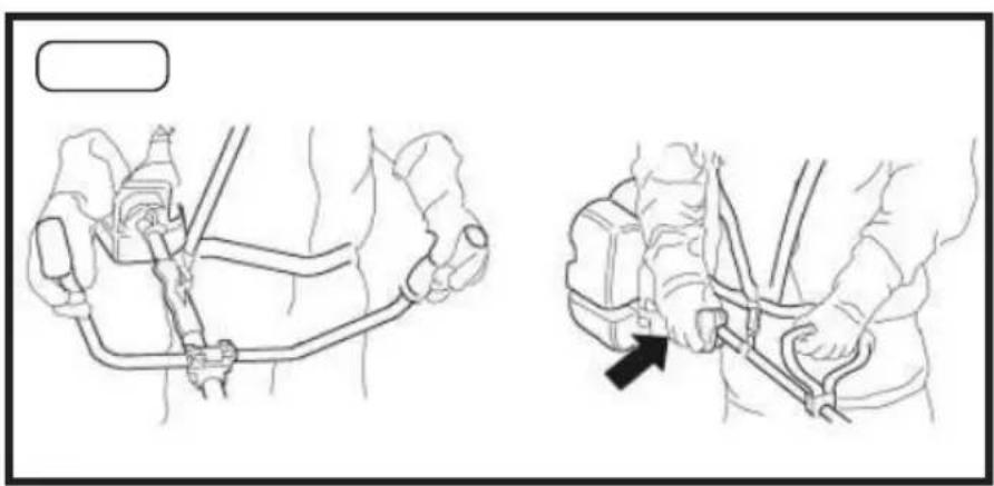
natural_image
Technical line drawing showing two mechanical assembly steps with hands and a black arrow indicating a specific component (no text or symbols present)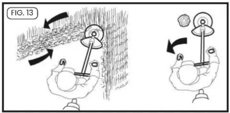
text_image
FIG. 13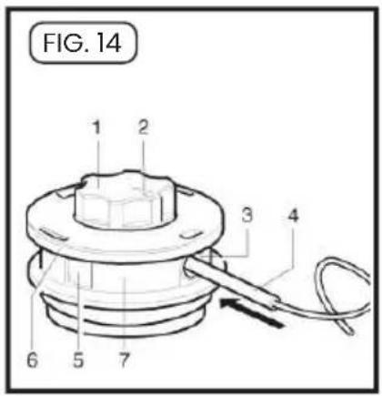
text_image
FIG. 14 1 2 3 4 6 5 7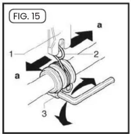
text_image
FIG. 15 a 1 2 a 3
text_image
FIG. 16 BENZ OIL MIX oil:service TC 1:25 4%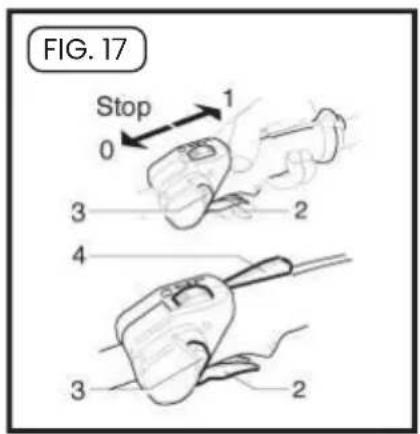
text_image
FIG. 17 Stop 0 3 2 4 3 2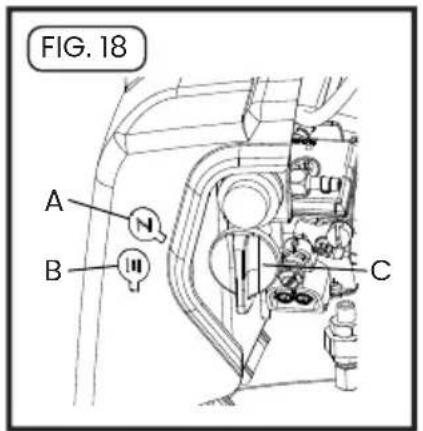
text_image
FIG. 18 A N B III C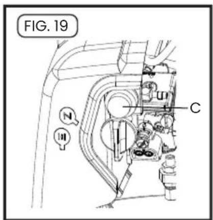
text_image
FIG. 19 N III C
text_image
FIG. 21 1 2 3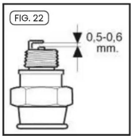
text_image
FIG. 22 0,5-0,6 mm.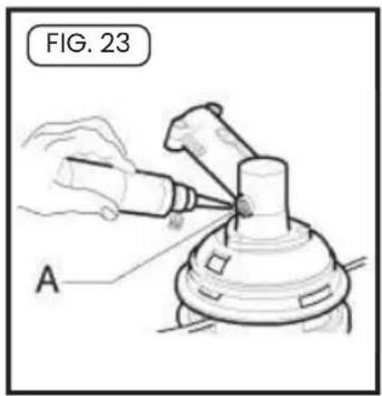
text_image
FIG. 23 A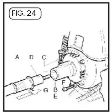
text_image
FIG. 24 A D C G B F E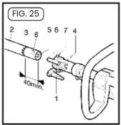
text_image
FIG. 25 2 3 8 5 6 7 4 40min. 1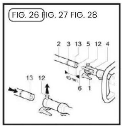
text_image
FIG. 26 FIG. 27 FIG. 28 13 12 40mm. 6 1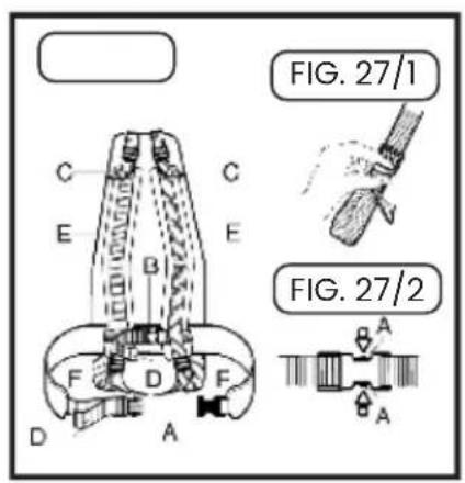
text_image
FIG. 27/1 FIG. 27/2
natural_image
Line drawing of a person in protective gear using a cleaning tool with a curved arrow indicating rotation (no text or symbols)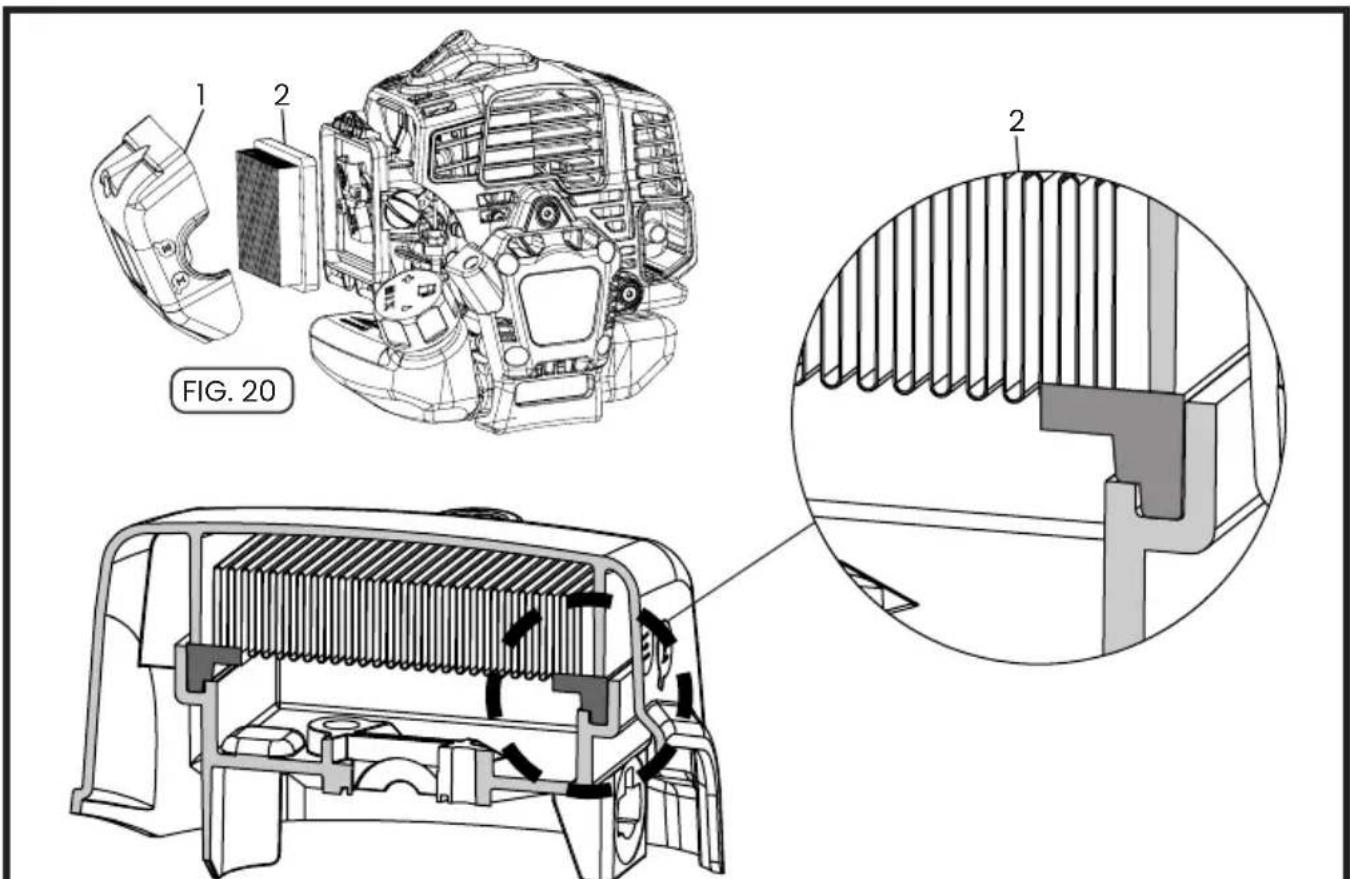
text_image
FIG. 20 1 2 2UTILIZZARE SOLO FILTRI DI RICAMBIO ORIGINALI - USE ONLY ORIGINAL SPARE FILTERS - UTILISER UNIQUEMENT DES FILTRES DE REMPLACEMENT D'ORIGINE - VERWENDEN SIE NUR ORIGINAL ERSATZFILTER - USAR SOLO FILTROS DE REPUESTO ORIGINALES - USAR APENAS FILTROS DE REPOSIÇÃO ORIGINAIS
DE - EINLEITUNG
Dear customer, thank you very much for having chosen an SABO product. For proper use of brushcutters and to avoid accidents, do not start work without having read the manual carefully. You'll find this guide on the explanations of operation of various components and instructions for the necessary inspections and maintenance.
N.B.: The manufacturer reserves the right to make changes at any time without notice. (CONTENTS PAG. 34)
NL-INLEIDING
text_image
15m 50 ft 360text_image
150m 50 ft 300- Symbol interpretation_Pag.34
- Safety precautions_Pag.35
- Description_Pag.36
- Assembly_Pag.38
- Use of brushcutter_Pag.40
- Preparing for use_Pag.41
- Regular maintenance_Pag.43
- Storage_Pag.44
- Warranty_Pag.44
- Specifications and Declaration of conformity_Pag.45
1. SYMBOL INTERPRETATION

Warning, danger and caution.

Read operator's instruction book before operating this machine

Choke full opened, run.

Choke closed, starting when engine is cold.

text_image
150m 50 ft 300°Keep all by standers at least 15 mt. (50 feet)


Wear safety head, eye and ear protection.
2. SAFETY PRECAUTIONS
- Read and understand this manual before operating this unit. Follow all warnings and safety instructions. Save this manual for future reference.
- Use only genuine replacement parts, failure to do so may cause poor fit and possible injury.
- Wear appropriate clothing and safety article such as: boots, heavy duty trousers, gloves, protective eye wear, ear protection and protective helmet.
- Do not wear loose clothing or unlaced items.
- Keep all by standers, children and pets at least 15 mt. (50 feet) during brushcutter use.
- Do not operate this brushcutter when you are tired, ill or under the influence of alcohol, drugs or medication. Replacement or if the disk appeared cracked, schegggiati or damaged in any way.
- Do not allow children to use the brushcutter.
- Keep firm footing and balance. Keep cutting attachment below waist level.
- Use the brush cutter only for the tasks explained in this manual.
- Inspect unit before each use, make sure that the throttle lever works freely, that the blade is free to move and is not in contact with any foreign object, fuel leaks. Replacement the disk when cracked, or damaged in any way.
- Start the brushcutter only in well-ventilated areas. Breathing exhaust fumes can kill.
- Make sure that the blade guard or the head and all shields are properly and securely attached.
- Carry the brushcutter with the engine off and with the protective blade cover on.
-
Never use for example, wire or wire-rope which can break off and become a dangerous projectile.
-
Never touch the blade or attempt any maintenance work while the engine is running. Wear protective gloves when handling or performing maintenance on the blade.
- When the engine is turned off make sure the cutting attachment has stopped before the unit is set down.
- Stop engine and allow to cool before refueling, fill the fuel tank with the engine off and away from heat sources and do not smoke while filling the tank or mixing fuel.
- Do not remove the fuel tank cap when the engine is running.
- Wipe spilled fuel from the unit. Move at least 3 Mt. (10 feet) from fuel in site before starting engine.
- Do not use fueling for cleaning operations.
- Do not check the spark plug near the cylinder port.
- Never work with a damaged muffler.
- Clear the area to be cut before each use. Remove all objects such as rocks, broken glass, nails, wire or string etc. which can be thrown or become entangled in the cutting attachment.
- Before storing, allow the engine to cool and empty the fuel tank.
- Store the unit so that sharp objects will not accidentally cause injury, away from heat sources and off the ground.
- Do not start the engine with the transmission not mounted.
- Be sure the cutting attachment is properly installed and securely fastened.
- Replacement or if the disk appeared cracked or damaged in any way
- Wear protective gloves when handling or performing maintenance on the blade.
- With the engine idling, the blade should not turn. If it does, regulate the idle adjustment screw.
ENGLISH
BC-510 PRO
- Transport the brushcutter with the guard mounted.
- To avoid the risk of injury, stop the engine and blade before removing material wrapped around the head or blade.
-
Always use a sharp blade, a dull blade is more likely to snag and thrust. Replace a dull blade. DO NOT attempt to sharpen.
-
Always stop engine and examine the blade after striking any hard object.
- In order to maintain performance and safety, be sure to use original spare parts and accessories approved by the manufacturer.
- When saw blade is used, fit the specific blade guard.
3. DESCRIPTION
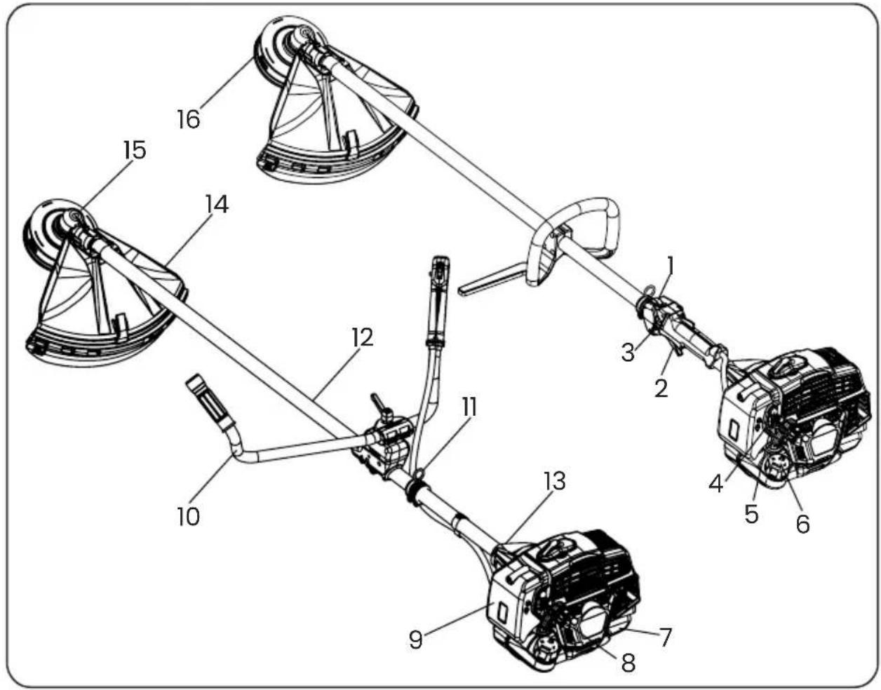
text_image
Technical diagram of a mechanical assembly with numbered components for identification- Switch
- Throttle lever
- 1/2 gas lever
- Choke
- Primer
- Fuel tank cap
- Fuel tank
-
Starter grip
-
Air filter
- Handle
- Harness hanger
- Transmission tube
- Engine/rod joint (antivibration system)
- Safety guard
- Bevel gear
- Head
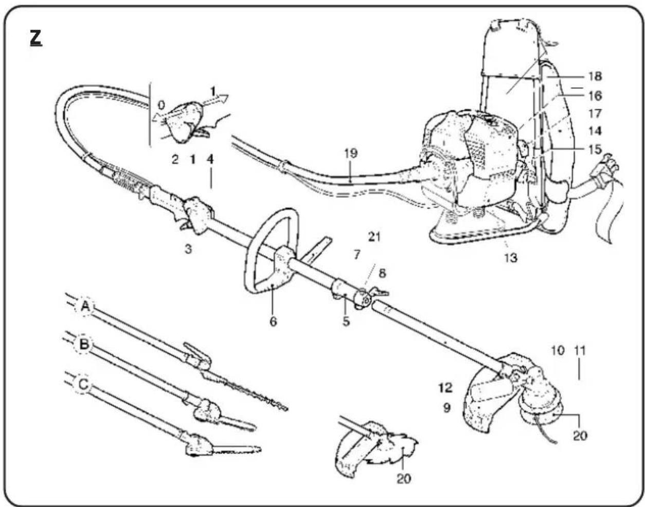
text_image
Z 18 16 17 14 15 19 21 3 7 8 6 5 A B C 10 11 12 9 20 20- Switch
- Throttle lock
- Throttle lever
- Half throttle
- Coupling
- Handle
- Safety bar
- Transmission locking lever
- Cutting tool protection
-
Bevel gear
-
Grease filler cap
- Transmission tube
- Fuel tank
- Harness
- Fuel tank cap
- Air filter
- Recoil starter handle
- Starter
- Flexible transmission
- SABO head
4. ASSEMBLY
ENGINE/TRANSMISSION ASSEMBLY B - BT
Fig.2 - Assemble the engine(B) to the transmission(A) and secure it using the screws(C). Ensure that the shaft and transmission tube are inserted correctly.
ENGINE/TRANSMISSION ASSEMBLY Z
Fig.24 - Thread the end of the hose(A)into the cap(B), making sure that the square tang of the hose shaft(G)is firmly seated in the bell.
-Tighten the screw(C), ensuring that it matches the hole(D) in the end hub of the casing.
- Mount the cap(B) on the engine(E) and secure it with the screws(F).
THROTTLE WIRE AND CABLE ASSEMBLY
Fig.3- Remove the air filter cover.
- Make sure that the throttle lever is not stuck under semi acceleration.
- Feed the accelerator cable(A) through the turnbuckle(B), ensuring that the cable sheath(C) rests against the inside of the turnbuckle(B), then hook the cable end into the clamp(E).
- Adjust the cable tension(A) by loosening the locknut(D) and turning the turnbuckle(B). Once the correct tension is reached, tighten the locknut(D). If the adjustment is correct, the throttle lever will have a free play of about 2 mm before the lever(E) moves.
- Connect the electrical cable terminal(F-G).
HANDLE (L) / HANDLEBAR (BT) ASSEMBLY
Fig.4 (Type L) – Remove the screws(1) and enlarge the handle(2) to fit into the tube(3) and secure it using the screws(1) and nuts(4). Place the safety barrier(5) in the appropriate slot and secure it using the screw(6) and nut(7). The position of the handle is adjustable according to the operator's requirements.
Fig.6 (Type BT) - Remove the lever(1). Open the bracket(4) and mount the two half-handles(2-3) in the lower bracket. Ensure that the ends of the two half-handles are positioned in the groove in the centre of the bracket, which are secured by means of the cover(4) and lever(1). The two half-handles can be adjusted independently of each other, as required by the operator, by loosening the lever(1).
SAFETY PROTECTION ASSEMBLY
Fig. 7 Mount the protection assembly (A + H) on the drive tube(B) and secure it by means of the U-bolt(C), screws(D), plate(G) and nuts(F).
IMPORTANT: Ensure that the U-bolt (C) is secured to the bevel gear(L) by means of the screw and washer(E). CAUTION: Use the guard(A + H) with the nylon threaded head.
Only use the guard(A)with the blades. For safety reasons saw blades cannot be used with the guard provided.
BLADE AND NYLON WIRE HEAD ASSEMBLY
Mounting the blade (4) see fig.8-9
- Unscrew the nut(1)clockwise; remove the cup(2) - (if the flange(3)has no nut guard) and the flange(3).
- Mount the blade(4)following the arrangement shown in Fig. 8. Ensure that the upper flange(5)is positioned correctly.
-Mount the blade making sure it is centred on the flange(5). Ensure correct direction of rotation (lettering or direction arrow pointing upwards with machine in working position).
- Install the lower flange(3), protection cup(2) - (if the lower flange has no nut protection), tighten the nut(1)anti-clockwise to 30 Nm (Kgm 3.0).
- To lock the nut(1), turn the blade until the hole in the upper flange corresponds with the hole in the bevel gear, and insert the Allen key (4 mm) provided.
Mounting the head (2) see fig.10-11.
- Mount the nylon threaded head following the illustrated arrangement:
Upper flange (1) and screw the nylon threaded head anti-clockwise.
Hand-tighten the head anti-clockwise as shown in Fig.10 after inserting the Allen key (4 mm) into the bevel gear hole.
For your safety, only use original cutting tools.
ACCESSORIES ASSEMBLY VERSION Z MACHINE
Fig.25 - Loosen the lever(1) anti-clockwise, thread the tube(2) into the sleeve(4) as far as the reference(3) (approx. 40mm), keeping the pin(7) facing upwards, to facilitate insertion of the shaft(5) into the shaft hub(6), rotate the tool a little to the right and a little to the left until the tool/tube is inserted correctly.
Turn the tool into the working position and lock it by means of the lever(1). For the safety of the operator the tube(2)has a hole(8)where the pin(7)must fit.
ASSEMBLY OF THE EXTENSION (on request and ONLY FOR TOOLS A - B - C)
Extension - machine coupling:
Fig.26 - Loosen the lever counterclockwise(1). Insert the extension tube(2) into the sleeve(4) to the reference(3) (about 40mm), keeping the pin(12) facing upwards. Turn the sleeve(10) to the same position as the sleeve(4), and lock it via the lever(1). For operator safety, the tube(2) and(8) have a hole(13) where the pin(12) is to be inserted.
Accessory coupling - extension:
Fig.26 - Loosen the lever(1) anticlockwise. Insert the tube(2) of the extension into the sleeve(4) up to the mark(3) (approx. 40mm), keeping the pin(12) facing upwards. Rotate the sleeve(10) to the same position as the sleeve(4) and lock it with the lever(1). For the safety of the operator, the tube(2) and(8) have a hole(13) where the pin(12) must fit.
CAUTION: For the use of accessories A - B - and C see the specific instruction manual attached to each accessory.
The machine extension (only for accessories A - B and C) must not exceed 1500 mm, otherwise it can be dangerous. Only one extension, either 750mm or 1500mm, may be used.
HARNESS
Fig.27 – The ergonomic SABO harness provides exceptional comfort and enables safe operation. In order to benefit from the advanced technology applied in this type of machine, it is necessary to correctly adjust the harness according to the operator's needs.
- Put the harness on, fasten the buckles (A-B).
- Adjust the harness tension by pulling or loosening the belt(D).
- Adjust the tension of the shoulder straps(E) by pulling or loosening the straps(F).
- Adjust the pressure of the backrest on the shoulders by pulling or loosening the straps (C).
CAUTION: THE WEIGHT OF THE MACHINE MUST BE SUPPORTED BY THE BELT(A). Fig.27/1 -
To loosen the straps, pull the end of the buckle upwards.
Fig.27/2 - To release the strap quickly, press the two levers (A) simultaneously as shown in the figure.
5. USE OF BRUSHCUTTER

WARNING: Before using the brushcutter, read the safety rules carefully.
If you are new to using the brushcutter, follow a training period first. Always carefully inspect the machine before use. Check for loose screws, damaged parts and fuel leaks. Check the condition of the anti-vibration system periodically. Avoid excessively prolonged use of the brushcutter, vibrations can be harmful. Before each use, remove the following from the area: stones, glass, ropes, metal parts and all foreign bodies that could get tangled up in the rotating parts or be thrown dangerously far away. Wear the harness and attach the brushcutter. Always keep both hands on the handles when operating the brushcutter (Fig.12). Use the brushcutter as illustrated in Fig. 13. To facilitate the cutting operation and for safety reasons, always place the guard latch against the material to be cut Fig.13. Always check that the disc is not cracked after accidental impacts against foreign objects. Replace any damaged or excessively worn accessories (discs, wire heads, guards, belts).
SABO NYLON WIRE HEAD, wire loading without removing the head fig.14.
- Always use the same diameter as the original wire so as not to overload the engine.
- Switch off the engine.
- Turn the knob (1) clockwise until the arrow (1) is aligned with one of the bushings (3).
- Insert the supplied tube (4) through the head.
- Thread the wire and remove the tube.
Join the ends of the thread and pull the thread so that the two branches of the thread are of the same length. - Turn the knob clockwise, taking care to stretch the two branches of the wire every 3 turns, until fully wound.
HEAD DISASSEMBLY
Fig.14 - Press the knob(1). Simultaneously press the tab(5) and partially pull the cover(6) off the head body(7). While keeping the knob pressed, press the other tab and pull the cover off.
HEAD ASSEMBLY
Fig.14 - Place the bushings(3) into their seats in the cover(6). Fit the spool in the cover(6). Position the spring on the spool or inside the head housing(7).
Fit the cover/rocket/bushing into the head body, ensuring that the tabs(5) are in place.
OPERATION
Fig.14 - To lengthen the thread: turn the head while keeping the motor running. Knob (1) on the ground. Each click corresponds to approx. 3 cm. of wire extension.
WARNING: Do not tap the head on hard surfaces, it can be dangerous.
6. PREPARATION FOR USE
PRELIMINARY OPERATIONS
Fig.15 - Adjusting the harness and position of the brushcutter.
Put on the harness, hook the brushcutter(1) onto the belt via the hook(2). Position the buckle to obtain the correct height for the brushcutter. By loosening the screw(3) adjust the hook(2) so that the disc or brushcutter head hangs approximately 5 cm above the ground.
FUEL
Fig.15 -2 STROKE - WARNING: : The brushcutter is equipped with a 2-stroke engine, therefore only fuel mixed with special oil for 2-stroke engines should be used. Only prepare the mixture required for use. Do not smoke and always refuel with the engine switched off and away from flames. Use fuel with an octane rating of not less than 90. Only mix petrol with 2-stroke oil. Use a different synthetic 2-stroke oil at a ratio of 1:50 (2%) or mineral oil at a ratio of 1:25 (4%).
Important: Stir the canister vigorously and for a long time, this should be carefully repeated each time fuel is taken from the canister. The characteristics of the mixture are subject to ageing and therefore alter over time. Do not use a mixture that has been prepared for several weeks, as this could result in engine damage. Fill the fuel tank only 3/4 full to allow the mixture to expand.
REFUELING
WARNING: Refueling must be carried out with the engine switched off. Slowly unscrew the tank cap to allow any excess pressure to escape.
Tighten the tank cap correctly after refuelling. Move the brushcutter at least 3 m away from the refuelling point before starting the engine. Thoroughly clean around the tank cap before refuelling. Dirt inside the tank causes engine malfunctions. Ensure that the mixture is homogeneous by shaking the canister or tank.
START THE ENGINE
Place the brushcutter on a flat, clear surface and check that the cutting tool is free to rotate. Set the switch to position(1)Fig. 17. Press the bulb (C) 5 or 6 times Fig. 19. Move the choke lever(C)to close position(A)Fig.18. Hold the brushcutter stationary and pull the starter lever (C) back to the original open position(B) Fig. 18. Repeat the starting manoeuvre until the engine starts. With the engine running, press the throttle(2)Fig. 17 to release it from the automatic half throttle position and bring the engine to idling speed.
WARNING: When the engine is already hot, do not press the bulb(C)Fig.19 and do not use the starter for starting. Do not suddenly release the starter rope, this could damage the starter unit.
STOP THE ENGINE
Move the throttle lever(2)Fig.17 to the idle position and wait a few seconds to allow the engine to cool down. Move the ground switch to the stop position(0)Fig. 17.

WARNING: When the engine is idling (2600 \~ 3000 rpm) the cutting tool must not rotate. If the idle speed is too high, unscrew the screw (H)Fig. 3 anticlockwise.

WARNING: After intensive use of the machine do not suddenly switch off the engine but let it idle for a few minutes to stabilise it. Mufflers fitted with catalytic converters become very hot during use and remain so for a long time after the engine has stopped. This happens even when the engine is idling. Contact can cause skin burns.
Never add fuel to a machine when the engine is running or hot. FIRE HAZARD.
Move at least 3 metres away from the refuelling position before starting the engine. DO NOT SMOKE!
7. PERIODIC MAINTENANCE
Periodically check that all brushcutter screws are in place and tight. Replace damaged, worn, cracked and uneven blades. Always check that the nylon wire head or blade is fitted correctly, and that the screw securing the blade is properly tightened.

CAUTION: USE ONLY ORIGINAL SABO SPARE FILTERS – THE USE OF NON-ORIGINAL FILTERS MAY CAUSE DAMAGE TO THE ENGINE.
AIR FILTER
Fig.20 -
- Check the air filter periodically depending on the working conditions.
- Remove cover
- Remove filter
- Use compressed air only
- Do not damage the filter with tools or wire brushes
- Do not wash the filter with water, petrol or liquids
- Do not oil the paper
- Replace the filter if damaged.
FUEL FILTER
Fig.21 - For cleaning or replacement, remove the cap(1) from the tank and pull out the filter(2) using a hook(1) or long-nose pliers. Periodically check the condition of the filter (2); if it is excessively dirty, replace it.
ENGINE
To prevent the engine from overheating, regularly remove dust and dirt from the slots, cylinder cover and cylinder fins, using a brush or compressed air.
SPARK PLUG
Fig.22 - Remove and clean the spark plug periodically (at least every 50 hours) and adjust the electrode gap (0.5 - 0.6 mm).
Replace the spark plug if excessively encrusted and worn and in any case every 100 operating hours. In the event of excessive fouling, check the carburetor setting, the mixture oil percentage and make sure that the oil is of good quality and of the type for 2-stroke engines.
BEVEL GEAR
Fig.23 - Every 50 hours of operation, add specific grease through hole(A) in the gearbox.
DISC
Always check the general condition of the blade. Replace the blade as soon as cracks or breaks appear.
8. STORAGE
Follow all maintenance rules described above. Clean the brushcutter thoroughly and grease the metal parts. Empty the fuel tank and run the engine until the remaining fuel is used up. Store the brushcutter in a dry environment. Remove the spark plug, pour some oil into the cylinder, rotate the crankshaft a few times through the starter to distribute the oil, refit the spark plug.
CAUTION: All maintenance work not listed in this manual must be carried out by an authorised workshop.
9. WARRANTY
The attached, current SABO guarantee conditions apply exclusively
The images in this manual are for illustrative purpose only
and may differ from the actual appearance of the product.
The information contained in this manual are subject to change without notice.
10. TECHNICAL SHEET AND DECLARATION OF CONFORMITY
ACTIVE s.r.l. - Via Delmoncello, 12 - 26037 S. Giovanni in Croce (CR) declares under its own responsibility that the machines:
| MODEL BC-510 PRO | |
| DISPLACEMENT cm3 50,9 | |
| POWER Kw / CV 2,5 / 3,4 | |
| MAXIMUM ENGINE RPM 9500-10500 rpm | |
| MINIMUM ENGINE RPM 2800-3000 rpm | |
| CARBURETOR | WT with membrane - HDA type primer |
| IGNITION Electronic | |
| FUEL TANK CAPACITY 1,1 liters | |
| CLUTCH 78 mm | |
| ANTI-VIBRATION SYSTEM | Engine/Transmission+Twin damper |
| HANDLEBAR / GRIP Bicycle | |
| THROTTLE | Safety device with automatic release |
| TRANSMISSION TUBE ∅ 30 mm | |
| BEVEL GEAR RATIO 1:1,87 | |
| WEIGHT Kg. (dry without cutting unit) | 8,7 |
are compliant with the requirements established by the directives:
| STAGE V | |
| MODEL BC-510 PRO | |
| FROM SERIAL N. 2503S | AXXXX |
| DIRECTIVES | 2006/42/CE - 2014/30/CE - 2002/44/CE - UE 2016/1628 - 2000/14/CE (Annex V) |
| MODEL TOOL | SOUND PRESSURE LEVEL db(EN ISO 22868) | ACOUSTIC POWER LEVEL db(EN ISO 22868) | VIBRATIONS LEVEL (m/s ^2 )(UNI EN ISO 22867)R L | ||
| BC-510 PRO | 91---93 | 110---113 | 2,0 / 1,9 2,5 | / 2,3 | |
| BLADE DIAMETER 300 mm |
The technical documentation is deposited in the Technical Management.
ALBERTO GRIFFINI
C.E.O. ACTIVE S.r.l.
Via Delmoncello, 12
26037 San Giovanni in Croce (CR) - ITALY
01/09/2023
Alphisto Griffin
INHOUDSOPGAVE
text_image
150m 50 m 300°text_image
150m 50 m 300text_image
150m 50 m 300°MONTAGGIO IMPUGNATURA (L) / MANUBRIO (BT)
text_image
150m 50 m 300°text_image
150m 50 m 300°text_image
150m 50 ft 300text_image
150m 50 ft 360Ohranite razdaljo do ljudi najmanj 15 metrov.