
60-PRO T PUSH - Lawn mower SABO - Free user manual and instructions
Find the device manual for free 60-PRO T PUSH SABO in PDF.

| Brand | SABO |
| Model | 60-PRO T PUSH |
| Product type | Push lawn mower |
| Intended use | Cutting grass, shrubs and brush on flat terrain with max slope 15° |
| Engine | Honda GCVx200, 3.7 kW, 2800 rpm |
| Starting | Recoil starter |
| Fuel | Unleaded gasoline |
| Cutting width | 600 mm maximum |
| Cutting height | 20-100 mm (adjustable by moving blocks) |
| Dimensions (L × W × H) | 1480 × 640 × 1150 mm |
| Dry weight | 40.5 kg |
| Sound level (LWA) | 98 dB(A) |
| Vibrations on the handlebar | 4.4 m/s² (uncertainty 2.2 m/s²) |
| Wheels | Pneumatic 16" |
| Drive | None (push model) |
| Handlebar adjustment | 3 tilt positions (for people of different heights) |
| Safety devices | Protective cover for the cutting unit and drive; automatic blade stop when releasing the guide bar |
| Warranty | SABO conditions (see manual) |
| Routine maintenance | Check oil level every 8 h, clean air filter every 4 h |
| Spare parts | Use exclusively SABO original parts; contact an authorized dealer |
| Certifications | CE, UKCA (according to Machinery Directive 2006/42/EC) |
| Tank capacity | Not specified in the manual (approx. 1 L) |
Frequently Asked Questions - 60-PRO T PUSH SABO
User questions about 60-PRO T PUSH SABO
0 question about this device. Answer the ones you know or ask your own.
Ask a new question about this device
Download the instructions for your Lawn mower in PDF format for free! Find your manual 60-PRO T PUSH - SABO and take your electronic device back in hand. On this page are published all the documents necessary for the use of your device. 60-PRO T PUSH by SABO.
USER MANUAL 60-PRO T PUSH SABO
Original instructions
Nederlands

1 VORWORT....2
2 ALLGEMEINE INFORMATIONEN....4
II Fabbricante/The Manufacturer
ECOTECH ITALIA SRL via Dovizi 18 47122 Forlì FC - ITALIA,
is in accordance with:
• European Regulation 2006/42/EC and with the relevant national provisions;
- European Regulation 2000/14/EC and subsequent amendments, relating to the noise emission in the environment by equipment for use outdoors.
Conformity assessment was performed according the procedure laid in Annex VI of European Regulation no. 2000/14/EC.
The person authorized to compile the Technical Construction File is Mr. Roberto Romboli at ECOTECH ITALIA S.r.l. via Copernico, 85 47122 Forlì FC - ITALY. The Technical Construction File required 2006/42/EC Directive is maintained at the corporate headquarters.
All of the instructions, as per the owner manual supplied with the machine, must be followed as well as all of the safety and accident prevention standards in force in the Country of use. The machine bears the CE Mark.
Data: 04/03/2023
Il Legale Rappresentante / Signature of Legal Representative Roberto Romboli


DICHIARAZIONE DI CONFORMITA' / CONFORMITY DECLARATION (All. II-A Dir. 2006/42/CE)
II Fabbricante/The Manufacturer
ECOTECH ITALIA SRL via Dovizi 18 47122 Forlì FC - ITALIA,
Is in accordance with:
• European Regulation 2006/42/EC and with the relevant national provisions;
- European Regulation 2000/14/EC and subsequent amendments, relating to the noise emission in the environment by equipment for use outdoors.
Conformity assessment was performed according the procedure laid in Annex VI of European Regulation no. 2000/14/EC.
The person authorized to compile the Technical Construction File is Mr. Roberto Romboli at ECOTECH ITALIA S.r.l. via Copernico, 85 47122 Forl FC - ITALY. The Technical Construction File required 2006/42/EC Directive is maintained at the corporate headquarters.
All of the instructions, as per the owner manual supplied with the machine, must be followed as well as all of the safety and accident prevention standards in force in the Country of use. The machine bears the CE Mark.
Data: 04/03/2023
Il Legale Rappresentante / Signature of Legal Representative
Roberto Romboli
EGOTECH ITALDA a.e.l. Via Obpomledo 80-47122-FORLF FU Tel: 0548-774314 - Fax 0643 776888 Q.F. a P. IVA 03994770400
Abbildung 4-2

Abbildung 4-3
4.4 VORABKONTROLLEN

60-PRO T DRIVE
60-PRO T PUSH

50-PRO C DRIVE
60-PRO T PUSH
50-PRO C DRIVE
2 INFORMATIONS GÉNÉRALES....4
II Fabbricante/The Manufacturer
ECOTECH ITALIA SRL via Dovizi 18 47122 Forlì FC - ITALIA,
is in accordance with:
• European Regulation 2006/42/EC and with the relevant national provisions;
- European Regulation 2000/14/EC and subsequent amendments, relating to the noise emission in the environment by equipment for use outdoors.
Conformity assessment was performed according the procedure laid in Annex VI of European Regulation no. 2000/14/EC.
The person authorized to compile the Technical Construction File is Mr. Roberto Romboli at ECOTECH ITALIA S.r.l. via Copernico, 85 47122 Forlì FC - ITALY. The Technical Construction File required 2006/42/EC Directive is maintained at the corporate headquarters.
All of the instructions, as per the owner manual supplied with the machine, must be followed as well as all of the safety and accident prevention standards in force in the Country of use. The machine bears the CE Mark.
Data: 04/03/2023
Il Legale Rappresentante / Signature of Legal Representative Roberto Romboli


DICHIARAZIONE DI CONFORMITA' / CONFORMITY DECLARATION (All. II-A Dir. 2006/42/CE)
II Fabbricante/The Manufacturer
ECOTECH ITALIA SRL via Dovizi 18 47122 Forlì FC - ITALIA,
Is in accordance with:
• European Regulation 2006/42/EC and with the relevant national provisions;
- European Regulation 2000/14/EC and subsequent amendments, relating to the noise emission in the environment by equipment for use outdoors.
Conformity assessment was performed according the procedure laid in Annex VI of European Regulation no. 2000/14/EC.
The person authorized to compile the Technical Construction File is Mr. Roberto Romboli at ECOTECH ITALIA S.r.l. via Copernico, 85 47122 Forl FC - ITALY. The Technical Construction File required 2006/42/EC Directive is maintained at the corporate headquarters.
All of the instructions, as per the owner manual supplied with the machine, must be followed as well as all of the safety and accident prevention standards in force in the Country of use. The machine bears the CE Mark.
Data: 04/03/2023
Il Legale Rappresentante / Signature of Legal Representative
Roberto Romboli

EGOTECH ITALDA a.e.l. Via Obpomledo 80-47122-FORLY FU Tel: 0548-774314 - Fax 0643 776888 Q.F. a P. IVA 03994770400
Illustration 3-1 Composants 60-PRO T DRIVE
1 SUPPORT D'INTERRUPTEUR DE SÉCURITÉ TONDEUSE
2 OUTIL DE COUPE CÂBLE BOWDEN
3 CÂBLE BOWDEN D'ENTRAÎNEMENT
4 BOUCHON DE CARBURANT
5 FILTRE À AIR
6 GOULOT DE REMPLISSAGE D'HUILE AVEC JAUGE
7 POIGNÉE DE CORDE DE DÉPART
8 LEVIER À GAZ
9 LEVIER D'ENTRAÎNEMENT
SA700024 (60-PRO T PUSH)
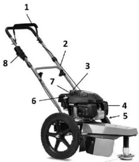
Illustration 3-2 Composants 60-PRO T PUSH
1 SUPPORT D'INTERRUPTEUR DE SÉCURITÉ TONDEUSE
2 OUTIL DE COUPE CÂBLE BOWDEN
3 CAPUCHON DE CARBURANT
4 FILTRE À AIR
5 POSITION TRANSVERSALE DE L'AXE
6 GOULOT DE REMPLISSAGE D'HUILE AVEC JAUGE
7 POIGNÉE DE CORDE DE DÉPART
8 LEVIER À GAZ
SA711024 (50-PRO C DRIVE)
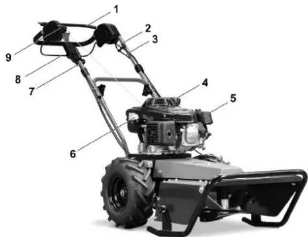
Figure 3-3 : Composants 50-PRO C DRIVE
1 SUPPORT D'INTERRUPTEUR DE SÉCURITÉ TONDEUSE
2 OUTIL DE COUPE CÂBLE BOWDEN
3 CÂBLE BOWDEN D'ENTRAÎNEMENT
4 BOUCHON DE CARBURANT
5 FILTRE À AIR
6 GOULOT DE REMPLISSAGE D'HUILE AVEC JAUGE
7 LEVIER À GAZ
8 LEVIER D'ENTRAÎNEMENT
9 POIGNÉE DE CORDE DE DÉPART
3.1 PRINCIPE DE FONCTIONNEMENT
4.1 TRANSPORT ET MANUTENTION
Illustration 4-2

Illustration 4-3
4.4 CONTRÔLES PRÉLIMINAIRES
60-PRO T DRIVE

60-PRO T PUSH
50-PRO C DRIVE
60-PRO T DRIVE

60-PRO T PUSH

50-PRO C DRIVE
Illustration 7-4: Remplacement du fil
1.1 General considerations ......2
1.2 Operator groups 2
2 GENERAL INFORMATION......4
2.1 Characteristics of the manufacturer ....4
2.2 Machine identification data and rating plates 4
2.3 Explanations....4
2.4 Safety regulations....8
2.5 Guarantee 8
2.6 Precautions to be taken by the customer 8
3 DESCRIPTION OF THE MACHINE....8
3.1 Functional principle 9
3.2 Dimensions....9
3.3 Ambient conditions 9
3.4 Lighting....9
3.5 Vibrations 9
3.6 Noise emissions 9
3.7 Technical data 10
4 INSTALLATION....10
4.1 Transport and handling 10
4.2 Storage....10
4.3 ASSEMBLY 10
4.4 Preliminary checks 11
4.5 Waste disposal 11
5 SAFETY 12
5.1 General warnings....12
5.2 Restrictions on use 12
5.3 Hazardous areas....12
5.4 Safety devices 12
5.5 Sticker 12
5.6 Residual risks 13
6 USE OF THE MACHINE....13
6.1 Settings 13
6.2 Operating modes....14
6.3 Normal stopping 14
6.4 Emergency stop 14
7 MAINTENANCE 14
7.1 Maintenance status 14
7.2 Cleaning 14
7.3 Lubrication....14
7.4 Proper maintenance 14
7.5 Extraordinary maintenance 15
7.6 Diagnosis and troubleshooting....15
8 SPARE PARTS ACCESSORIES....17
8.1 Customer service 17
8.2 Spare parts....17
9 PURPOSE OF THE OPERATING INSTRUCTIONS ....17
9.1 Storage of the operating instructions....17
9.2 Methodology for updating the operating instructions....18
9.3 GLOSSARY....18
EN
1 FOREWORD
IMPORTANT!
This machine was built in accordance with the Machinery Directive 2006/42/EC and is labelled with the mark.
BEFORE CARRYING OUT ANY WORK ON THE MACHINES, THE OPERATORS AND THE RESPONSIBLE TECHNICIANS MUST CAREFULLY READ THE INSTRUCTIONS CONTAINED IN THIS MANUAL (AND THE ENCLOSED INSTRUCTIONS) AND OBSERVE THEM WHEN CARRYING OUT THE WORK.
IF IN DOUBT ABOUT THE CORRECT INTERPRETATION OF THE INSTRUCTIONS, CONTACT THE NEAREST CUSTOMER SERVICE CENTRE.
1.1 GENERAL CONSIDERATIONS
The manual is divided into separate chapters, each of which is aimed at a specific operator group (OPERATOR/USER, MAINTENANCE TECHNICIAN), which define the skills required to operate the machine safely.
The order of the chapters corresponds to the chronological logic of the machine's operating life.
To facilitate direct understanding of the text, terms and abbreviations are used, the meaning of which is shown in the following tables in paragraph 1.2.2 Pictograms and paragraph 9.3 GLOSSARY is indicated.
Below is the meaning of the pictograms for:
- the various hazard levels during "Use and maintenance" of the machine;
• the operator qualification; - safety, which are attached to the machine itself.
With their help, the necessary information for the correct and safe use of the machine can be communicated quickly and clearly.
1.2 OPERATOR GROUPS
These instructions are intended for:
Operators/users, qualified personnel who are authorised to maintain the machine and all persons who intervene or work with the machine at any level.
1.2.1 Qualification of the operator groups
The machine is intended for use by qualified persons who:
- are of legal age;
• are physically and mentally capable of carrying out work with a certain degree of technical difficulty;
• have been adequately instructed in the use and maintenance of the machine;
• are able to understand and implement the operating instructions and safety instructions;
• are familiar with the emergency procedures and their implementation; - are able to operate the specific type of device;
• are familiar with the relevant regulations;
• have understood the operating procedures specified by the manufacturer of the machine.
1.2.2 Pictograms
Descriptions preceded by a pictogram:
Very important information/regulations, especially with regard to safety.
Non-compliance may result in the following:
• Hazards for the safety of the operator;
- Loss of the contractual guarantee;
- Disclaimer of the manufacturer.
1.2.2.1 Pictograms for information and/or procedures
| Pictogram | Description of the | |
 | DANGER!!!Information or procedures which, if not strictly adhered to, could result in death or serious injury to persons. | |
 | ATTENTION!!!Information or procedures which, if not strictly adhered to, could result in death or serious injury to persons. | |
 | CAUTION!Information or procedures which, if not strictly adhered to, may result in minor injury or damage to the machine. | |
 | WARNINGInformation or procedures that inform the operator on the best use of the machine in order to extend its service life, prevent damage and optimise its operation in compliance with regulations. | |
| NOTEImportant information or procedures. | ||
Table 1-1: Pictograms for information and/or procedures
1.2.2.2 Pictograms for operator qualification
| Sym. | Description of the | |
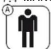
 | A) General labourer: A worker without special skills who can only carry out simple tasks under the instruction of qualified technicians. | |
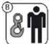
 | B) Lifting and handling equipment operator: An operator who is qualified to use hoists and conveyors to handle materials and machinery (in strict compliance with the manufacturer's instructions), in accordance with the laws in force in the country of the machine user. | |
 | C) Maintenance mechanic: Qualified technician who is able to operate the machine under normal conditions, operate it in inching mode (JOG) with the safety devices deactivated and work on mechanical parts in order to carry out the necessary adjustments, maintenance and repairs. As a rule, he is not authorised to work on electrical systems when voltage is present. | |
 | D) Maintenance electrician: Qualified technician who is able to operate the machine under normal conditions, operate it in inching mode (JOG) with the safety devices deactivated, and is responsible for all electrical adjustment, maintenance and repair work. He can work in switch cabinets and distribution boxes when voltage is applied. | |
 | E) Manufacturer's technician: Qualified technician provided by the manufacturer to carry out complex work in special situations or after consultation with the user. Depending on the case, this may involve mechanical and/or electrical and/or electronic and/or software skills. | |
Table 1-2: Pictograms for operator qualification
1.2.2.3 Safety-related pictograms
Pictograms preceded by a triangle mean DANGER.
| Pictogram | Designation | |
 |  | We recommend that you read these operating instructions before commissioning the machine and before starting work. |
 |  | Never touch moving belts or pulleys as they can cause serious damage to the operator. Never service the machine with the engine running under any circumstances. Only open the bonnet of the machine when the engine is switched off. |
 |  | The fuel is highly flammable and must therefore be handled with particular care and attention. Never, under any circumstances, top up with fuel while the engine is running, when smoking or in the presence of flames or sparks.The exhaust fumes are highly harmful and can cause serious discomfort or death. The machine must never be started in a closed room without a suitable intake pipe that discharges the engine exhaust gases to the outside. In any case, it is best to start the machine only in a well-ventilated area and outdoors. |
 |  | The machine can throw stones, grass clippings or other objects during operation. |
 |  | To prevent damage to third parties, the operator should ensure that there are no other persons within a radius of at least 30 metres before using the machine. |
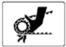
 |  | Do not place your hands or feet near the rotating blades or under the guard: Risk of injury to limbs. |
 | General danger | |
Table 1-3: Safety-related pictograms
The units of measurement used are those of the International System (SI).
EN
2 GENERAL INFORMATION
2.1 CHARACTERISTICS OF THE MANUFACTURER
ECOTECH ITALIA s.r.l. Via Dovizi, 18 - 47122 Forlì (FC) - Italy -
Phone: +39 (0)543 774314 E-mail: info@ecotechitalia.com
CUSTOMER SERVICE/SPARE PARTS:
Customer service is provided by an authorised specialist dealer. For Germany, you can find the authorised dealer on our homepage at www.sabo-online.com and the "Service" / "Specialist dealer search" tab to find your nearest specialist dealer. If you are unsure, please contact your sales partner.
2.2 MACHINE IDENTIFICATION DATA AND RATING PLATES
Each machine is labelled with a CE type plate on which the reference data of the machine are indelibly marked.
This reference data must always be quoted in all communications with the manufacturer or customer service centres.
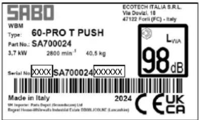
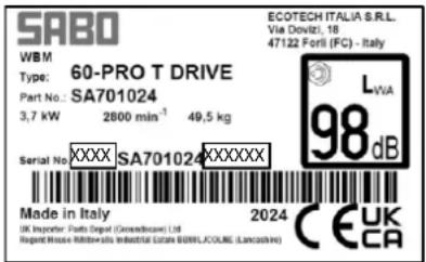
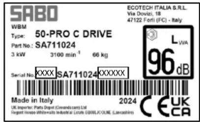
Illustration 2-1: CE type plates
The position of the rating plate on the machine may vary depending on the machine.
2.3 EXPLANATIONS
The machine is manufactured in accordance with the relevant European Union Directives in force at the time it is placed on the market.
II Fabbricante/The Manufacturer
ECOTECH ITALIA SRL via Dovizi 18 47122 Forlì FC - ITALIA,
is in accordance with:
• European Regulation 2006/42/EC and with the relevant national provisions;
- European Regulation 2000/14/EC and subsequent amendments, relating to the noise emission in the environment by equipment for use outdoors.
Conformity assessment was performed according the procedure laid in Annex VI of European Regulation no. 2000/14/EC.
The person authorized to compile the Technical Construction File is Mr. Roberto Romboli at ECOTECH ITALIA S.r.l. via Copernico, 85 47122 Forl FC - ITALY. The Technical Construction File required 2006/42/EC Directive is maintained at the corporate headquarters.
All of the instructions, as per the owner manual supplied with the machine, must be followed as well as all of the safety and accident prevention standards in force in the Country of use. The machine bears the CE Mark.
Data: 04/03/2023
Il Legale Rappresentante / Signature of Legal Representative Roberto Romboli


DICHIARAZIONE DI CONFORMITA' / CONFORMITY DECLARATION (All. II-A Dir. 2006/42/CE)
II Fabbricante/The Manufacturer
ECOTECH ITALIA SRL via Dovizi 18 47122 Forlì FC - ITALIA,
Is in accordance with:
• European Regulation 2006/42/EC and with the relevant national provisions;
- European Regulation 2000/14/EC and subsequent amendments, relating to the noise emission in the environment by equipment for use outdoors.
Conformity assessment was performed according the procedure laid in Annex VI of European Regulation no. 2000/14/EC.
The person authorized to compile the Technical Construction File is Mr. Roberto Romboli at ECOTECH ITALIA S.r.l. via Copernico, 85 47122 Forl FC - ITALY. The Technical Construction File required 2006/42/EC Directive is maintained at the corporate headquarters.
All of the instructions, as per the owner manual supplied with the machine, must be followed as well as all of the safety and accident prevention standards in force in the Country of use. The machine bears the CE Mark.
Data: 04/03/2023
Il Legale Rappresentante / Signature of Legal Representative
Roberto Romboli

EGOTECH ITALDA a.e.l. Via Obponledo 80-47122-FORLY FU Tel: 0548-774314 - Fax 0643 776568 Q.F. a P. NA 03994770400
Table 2-1: Extract from the declaration of conformity
2.4 SAFETY REGULATIONS
The machine was realised in compliance with the specifications in the technical safety standards listed below:
| DIN EN ISO 12100-1 | Safety of machinery - Basic concepts, general principles for design - Part 1: Basic terminology, methodology) |
| DIN EN ISO 12100-2 | Safety of machinery - Basic concepts, general principles for design - Part 2: Technical principles) |
| DIN EN ISO 14121-1 | Safety of machinery - Guidelines for risk assessment |
| DIN EN ISO 13857 | Safety of machinery - Safety distances to prevent hazard zones being reached by the upper and lower limbs. |
| DIN EN 349 | Safety of machines - minimum distances to avoid crushing of body parts. |
| DIN EN ISO 3744 | Acoustics - Determination of sound power levels of noise sources from sound pressure measurements |
| DIN EN ISO 20643 | Mechanical vibration - Hand-held and hand-guided machinery - Basic procedure for the assessment of vibration emission |
Table 2-2: Technical safety regulations
2.5 GUARANTEE
Only the enclosed, current SABO guarantee conditions apply.
2.6 PRECAUTIONS TO BE TAKEN BY THE CUSTOMER
For machines for which more than one mowing deck is provided, the user is responsible for installing the mowing deck and must carefully follow the instructions supplied with the accessory.
3 DESCRIPTION OF THE MACHINE
SA701024 (60-PRO T DRIVE)
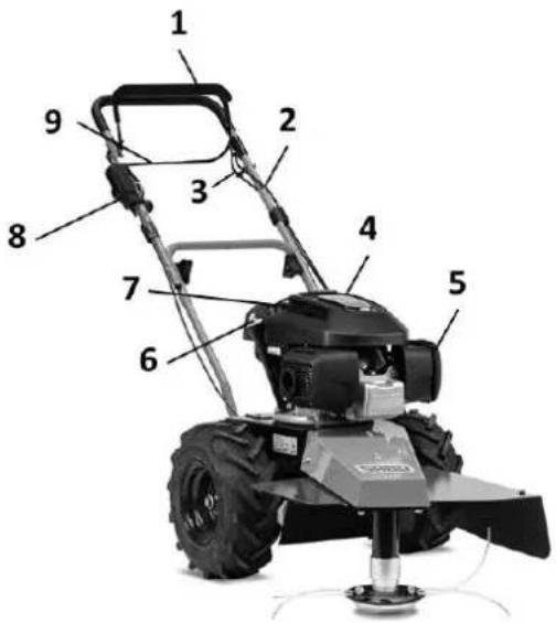
Illustration 3-1Components 60-PRO T DRIVE
1 SAFETY SWITCH BRACKET MOWER
2 CUTTING TOOL BOWDEN CABLE
3 DRIVE BOWDEN CABLE
4 FUEL CAP
5 AIR FILTER
6 OIL FILLER NECK WITH DIPSTICK
7 STARTER ROPE HANDLE
8 GAS LEVER
9 DRIVE GEAR LEVER
SA700024 (60-PRO T PUSH)

Illustration 3-2Components 60-PRO T PUSH
1 SAFETY SWITCH BRACKET MOWER
2 CUTTING TOOL BOWDEN CABLE
3 FUEL CAP
4 AIR FILTER
5 AXLE TRANSDUCER
6 OIL FILLER NECK WITH DIPSTICK
7 STARTER ROPE HANDLE
8 GAS LEVER
SA711024 (50-PRO C DRIVE)

Figure 3-3: Components 50-PRO C DRIVE
1 SAFETY SWITCH BRACKET MOWER
2 CUTTING TOOL BOWDEN CABLE
3 DRIVE BOWDEN CABLE
4 FUEL CAP
5 AIR FILTER
6 OIL FILLER NECK WITH DIPSTICK
7 GAS LEVER
8 DRIVE GEAR LEVER
9 STARTER ROPE HANDLE
3.1 FUNCTIONAL PRINCIPLE
3.1.1 Intended use
The machine you have purchased has been developed and built for use on level ground with a maximum slope of 15° . The working options vary depending on the mowing deck:
| Type of mowing deck | Intended use |
| 60-PRO T DRIVE | Edging and cutting grass/shrubs/undergrowth, even in the presence of stones |
| 60-PRO T PUSH | Cutting grass/shrubs/undergrowth on uncultivated areas and in the undergrowth, particularly suitable for trimming and cutting on ground with stones |
| 50-PRO C DRIVE | Cutting grass/shrubs/undergrowth of medium to high height on uncultivated land and in undergrowth, under marginal working conditions |
The technical performance specified in these operating instructions relates exclusively to new products or to products that are in good operating condition as a result of following the instructions for use, inspection and maintenance.
Like any other mechanical device, the machine must be properly maintained and kept clean. Lubricate the machine as indicated. Observe the safety measures and instructions described in this manual and shown on the safety stickers.
3.2 DIMENSIONS
| Dimensions max. | |||
| Model | Length (mm) | Width (mm) | Height (mm) |
| 60-PRO T DRIVE | 1480 | 600 | 1150 |
| 60-PRO T PUSH | 1480 | 640 | 1150 |
| 50-PRO C DRIVE | 1800 | 600 | 1230 |
Table 3-1: Dimensions
3.3 AMBIENT CONDITIONS
The machine does not require any special environmental conditions. It can be used on both dry and wet grass, whereby care must be taken to ensure that the opening of the discharge chute is set to the greatest possible width so that the cutting unit does not become blocked, which would overload the engine.
3.4 LIGHTING
The machine has been designed and built so that it can work outdoors in daylight. When working at night, good artificial lighting of at least 150 lux (DIN EN 12646-2:2008) must be provided.
3.5 VIBRATIONS
Terms of use:
| 60-PRO T DRIVE | 60-PRO T PUSH | 50-PRO C DRIVE | |
| Engine speed during the test | 2800 U/min | 2800 U/min | 3100 U/min |
| vibrations on the handle bar aHW [m/s2] according to DIN-EN 12733 | 4,4 m/s2 | 4,4 m/s2 | 4,4 m/s2 |
| Measurement uncertainty K [m/s2] according to EN 12096 | 2,2m/s" | 2,2m/s" | 2,2m/s" |
3.6 NOISE EMISSIONS
The A-weighted equivalent continuous sound pressure level at the workplaces is:
| 60-PRO T DRIVE / 60-PRO T PUSH | 50-PRO C DRIVE |
| 98 dB(A) | 96 dB(A) |
Other phonometric measurements in the working environment must be carried out in accordance with the regulations applicable in the country of use.
EN
3.7 TECHNICAL DATA
| 60-PRO T DRIVE | 60-PRO T PUSH | 50-PRO C DRIVE | |
| Engine | Honda GCVx200 | Honda GCVx200 | Honda GXV160 |
| Engine Start | rope pull starter | ||
| Drive Unit | mechanical belt drive | -- | mechanical belt drive |
| Gears | 1 | -- | 1 |
| speed | 1.6 km/h | -- | 1.6 km/h |
| Cutting width | 20 cm from the right wheel | Max 600 mm | 500 mm |
| Cutting height | 30-45-60 mm | 20-100 mm | |
| Track gauge | 580 mm | 600 mm | 580 mm |
| Wheels | Pneumatic tyres 13" | 16" | Pneumatic tyres 13" |
| Dry weight | 49.5 kg | 40.5 kg | 66 kg |
| Noise level | 98 dB | 96 dB | |
Table 3-2: Technical data
4 INSTALLATION
4.1 TRANSPORT AND HANDLING

• Always proceed step by step when raising/lowering the machine.
- During inspections/maintenance/cleaning under the mower deck, the machine must always be tilted backwards (by lowering the handlebar to the ground) to prevent oil or fuel from leaking. This procedure must always be carried out with the engine switched off and parts at a standstill.
- When loading onto a vehicle, always use stable ramps, taking care to proceed at minimum speed and to keep the wheels of the machine within the guides.
4.1.1 Packaging
The machine is packed as shown in the following photo:
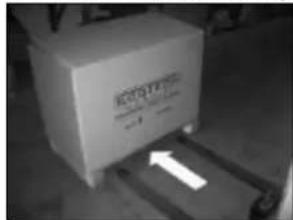
Illustration 4-1: Packaging with indication of lifting point/direction

CAUTION! POSITION THE LIFTING FORKS OF THE FORKLIFT TRUCK AT THE GRIPPING POINT SHOWN IN THE ILLUSTRATION!
4.2 STORAGE

The following is recommended for longer machine downtimes:
• Empty the fuel tank;
- Lubricate the cylinder with suitable products, which you can purchase from your dealer;
- Clean the air filter;
- Drain the remaining petrol from the carburettor chamber;
- Grease parts of the machine whose paintwork has been removed by wear or impact, as well as parts whose galvanisation is worn, to prevent possible rust formation.
4.3 ASSEMBLY
IMPORTANT
Ensure that the cables are not pinched, crushed, twisted or overstretched when fitting the guide rails! Always route the cables on the outside of the rail connection. A damaged cable can lead to a technical defect in the appliance.
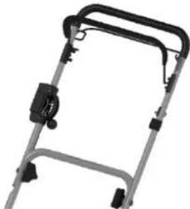
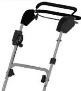
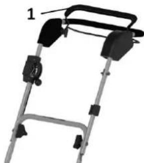
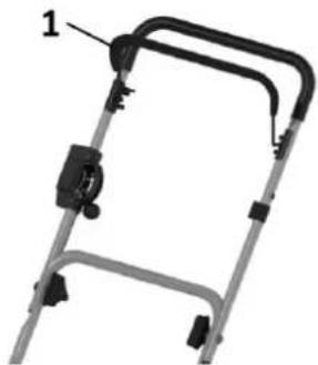
- Mounting the lower part of the guide rail: (Figure 4-2)
Remove the nuts (1), washers (2) and screws (3) from the tool bag and screw the lower part of the guide rail (5) tightly to the support bar (4) on the appliance.
There are 3 holes in the support bracket (4) for adjusting the rail inclination
Upper hole = steep bar position (for taller people)
Lower hole = flat bar position (for smaller people) - Mounting the upper part of the guide rail: (Figure 4-3)
Remove the grip nuts (1), washers (2) and screws (3) from the tool bag and tighten the upper part of the guide rail (5) with the lower part of the guide rail (4) by hand.
- Tighten all screw connections firmly.
• Finally, secure the cables to the lower part of the guide rail using the cable ties in the tool bag.
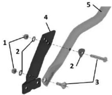
Illustration 4-2

Illustration 4-3
4.4 PRELIMINARY CHECKS
- Ensure that the stickers with the safety instructions are in order and in good condition.
- Ensure that the machine is free of dirt and plant residues.
- Ensure that all covers, grilles and guards are in order and in good condition.
Before starting the engine
• Visually check for fluid leaks and defective or missing parts. Carry out the necessary repairs before using the machine again.
- Ensure that the oil level is not below the minimum level: Unscrew the plug at the rear of the engine, wipe the dipstick with a cloth and screw the plug back on. Unscrew the plug again and ensure that the level is between the minimum and maximum markings. If the level is below the minimum value, top up the oil until the optimum level is reached (ask your dealer for the correct oil).

ATTENTION!! THE MACHINE IS SUPPLIED WITHOUT ENGINE OIL
- Ensure that all screws are firmly tightened.
- Check that all shifting brackets are in the neutral position.
Illustration 4-4: Idle position of the shifting brackets
60-PRO T DRIVE
60-PRO T PUSH

50-PRO C DRIVE
- Clean the air filter if it is dirty.
- Fill the machine with fuel using a funnel with filter.
- Open the fuel tap and, if the engine is equipped with one, operate the carburettor choke.
- For a cold start of the engine, move the throttle lever to the START position and wait a few minutes until the engine has reached operating temperature before bringing it up to full speed.
• Take the starter handle of the engine in your hand and then pull it firmly.

IT IS RECOMMENDED THAT YOU ALSO FOLLOW THE INSTRUCTIONS IN THE MOTOR MANUAL.
Before starting work, ensure that there are no persons, animals or objects within a radius of at least 30 metres; then start the engine and bring it to full speed as soon as it is warm.
4.5 WASTE DISPOSAL
The machine must be completely dismantled, whereby the parts must be separated according to their materials and the applicable waste disposal regulations must be observed.
EN
5 SAFETY
5.1 GENERAL WARNINGS
In these operating instructions and on the machine there are signs and labelling, followed by the danger sign below, which indicate a possible danger. It is therefore advisable to pay particular attention to the illustrations and labelling in order to ensure the safety of the operator and all persons within the operating range of the machine.

Read these operating instructions carefully before using the machine. Only the instructions in this operating manual will help you to use the machine efficiently and safely.
The machine can only be used safely if it is used in compliance with the regulations and restrictions described in this manual. Therefore, all safety instructions in this operating manual and the instructions for using the machine must be known and followed.
5.2 RESTRICTIONS ON USE
- Ensure that the machine is only used by persons who have read and understood these instructions.
- Do not allow children to use the machine.
- Do not wear loose clothing that could get caught in the moving parts of the machine.
- Only work in daylight or with good artificial lighting.
- It is strictly forbidden to carry persons/animals/loads on the machine during operation or during the transport process.
- Reduce the travelling speed when working on slopes and when turning to avoid losing control of the machine.
- Be very careful when approaching a ditch/bump/embankment.
- Switch off the motor before carrying out any work on the machine.
- Never work under the machine or under raised parts unless they are blocked and secured in position and always with the engine switched off.
• Always work crosswise on a slope, never uphill or downhill. - Keep away from electrical conductors and obstacles. Contact with electrical conductors can lead to electric shock and death.
• To avoid being hit by projected objects, the operator must wear the following:
○ PROTECTIVE MASK FOR THE FACE
○ WORK SUIT
o STURDY, HIGH SHOES
○ GLOVES
○ CAPE
5.3 HAZARDOUS AREAS
Cutting unit;
Drive mechanism;
- Never stand in front of the machine during operation: There is a risk of stones or objects being thrown out.
• Always keep a minimum distance of 30 metres: Outsiders should preferably stay to the side and at a sufficient distance.
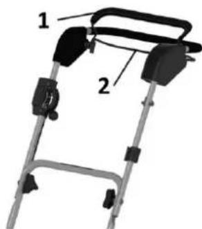
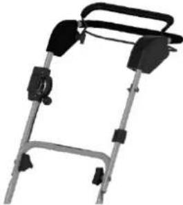
5.4 SAFETY DEVICES
Protective covers have been provided for both the cutting unit and the drive for the danger areas mentioned in the previous paragraph.
1 - Drive protective cover
2 - Protective cover for cutting unit
Illustration 5-1: Protective cover Model 60-PRO T DRIVE

DO NOT TAMPER WITH OR REMOVE THE SAFETY DEVICES.
5.5 STICKER
See Table 1-3: Safety-related pictograms for the meaning of the pictograms.
THE FOLLOWING ILLUSTRATION CAN BE FOUND ON THE MACHINE:
Illustration 5-2: Sticker on the machine

CAUTION: The machine has a cutting unit, which is why you should keep your hands and feet away and never work on the machine while the engine is running.
It is recommended that you do not work in areas with gravel, stones and other foreign objects that can be thrown away by the cutting blades and thus pose a great danger to people or objects in the vicinity. Ensure that people are at least 15 metres away from the machine. The operator must wear a protective mask for the face and possibly also rubber boots.

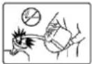
CAUTION: Do not under any circumstances place your hands near the swivelling mechanism of the machine, as this mechanism can crush your fingers.

THE APPLICATION OF THESE RULES IS NOT A WASTE OF TIME! IT HELPS TO PREVENT IRREPARABLE DAMAGE TO PERSONS OR PROPERTY AND ENSURE THE SAFETY OF THE OPERATOR.
5.6 RESIDUAL RISKS
Noise: Always wear hearing protection.
Vibrations: It is advisable to take breaks during work. Do not use the machine for more than 8 hours per day.
6 USE OF THE MACHINE
Dear customer, thank you for the trust you have placed in SABO-Maschinenfabrik GmbH and we hope that the use of your new machine will fully meet your expectations.
For optimum use of the machine and effective maintenance, we recommend that you read all the instructions and warnings in this brochure, which you must keep and always carry with the machine.

READ THE OPERATING INSTRUCTIONS CAREFULLY BEFORE STARTING UP THE MACHINE!
6.1 SETTINGS
Figure 6-2: Cutting height
| Model | speed | Steering | Engine | |
| 60-PRO T DRIVE | 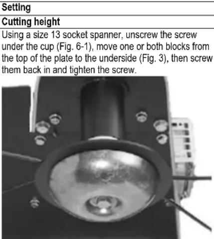 | Fixed speed 1.6 km/h | Apply slight pressure to the handle to steer to the right or left. | Observe the operating instructions for the motor. |
| 60-PRO T PUSH | 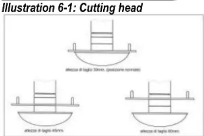 | Not applicable (push model) | ||
| Figure 6-2: Cutting height | ||||
| 50-PRO C DRIVE | Loosen the two rotary knobs and push the carriage down if the cutting height is to be increased, raise the carriage if it is to be reduced and then tighten the two rotary knobs again. | Speed: 1.5 - 1.9 - 3 km/h | ||
Table 6-1 Settings
EN
6.2 OPERATING MODES
6.2.1 WORKING ON A FLAT SURFACE
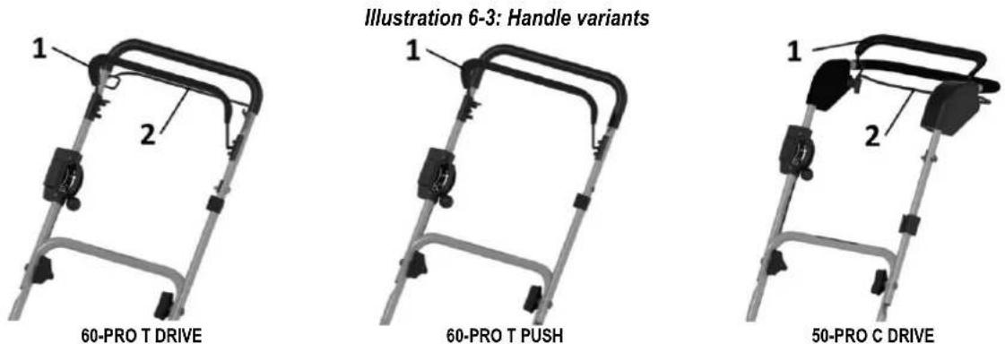
After carrying out the work described in point 4.4 and starting the engine, press the mower safety switch bracket (Illustration 6-3 No. 1), actuate the drive shift lever ((Illustration 6-3 No. 2) and start working, but proceed with the utmost caution.
6.3 NORMAL STOPPING
Once the work has been completed, the engine is brought to the STOP position by turning the throttle lever (or, if available, by pressing the stop switch, always after the engine speed has been brought to idle) and, if available, the petrol tap is turned off.
6.4 EMERGENCY STOP
If a fault occurs during operation, simply release the guide bar: The machine stops operation and rotation of the cutting unit.
To switch off the engine, please refer to the previous point.
7 MAINTENANCE
7.1 MAINTENANCE STATUS

Before carrying out maintenance work on the machine, switch off the engine and wait until the rotation of the blades has come to a complete standstill.
Failure to carry out maintenance work may result in damage to the machine and injury to the user and/or bystanders. This damage and injury is not covered by the warranty.
• Daily maintenance must be carried out by the user.
• The maintenance work after the first 10, 50 and 100 operating hours must be carried out by the dealer.
- Ask your dealer to check the machine if problems occur.
7.2 CLEANING

CAUTION!!! AVOID THE USE OF WATER JET PUMPS AT ALL COSTS.
7.3 LUBRICATION

Regularly lubricate/grease the mechanical parts that contribute to the movement of the moving parts of the machine, e.g. chains and gear wheels. Ask your dealer for the appropriate lubricant.
7.4 PROPER MAINTENANCE

In general, the oil level should be checked at least every 8 operating hours and the air filter should be cleaned every 4 hours or even more frequently if working in very dusty areas.
Remove any grass clippings from the motor head to ensure better air exchange.
To ensure proper operation of the machine, the engine should never be overloaded; if white smoke rises from the exhaust, the speed should be reduced.
Ask your dealer to carry out this work, which requires special equipment and expertise.
| Element to be controlled | Inspection | First 10 hours | Every 50 hours | Every 100 hours / year |
| Cutting unit belt | Check the belt tension. | |||
| Check wear condition.Replace if necessary. | ||||
| Drive shift bracket | Ensure that the machine does not move when the drive shift lever is in the idle position. | |||
| Brake | Check the effectiveness of the brake. | |||
| Frame | Check for rust and/or cracks. | |||
| Safety sticker | Check that they are all present and legible. | |||
| Protective devices | Check that they are firmly in place and in good condition. | |||
| Fuel tank and fuel lines | Ensure that there are no leaks and that the tank and pipes are in good condition. Replace if necessary. | |||
| Throttle lever | Check whether it is working. | |||
| Cutting system (knife, thread, disc) | Knives: Check that they are securely screwed down and in good condition.Replace if necessary.Thread: Check that it is tight. Replace if it is worn out.Disc: Check that it is firmly seated and in good condition. Replace if necessary. | |||
| Mower safety switch bracket | Check the correct cable tension. | |||
| Engine | Observe the operating instructions for the motor. |
Table 7-1: Extraordinary maintenance
7.6 DIAGNOSIS AND TROUBLESHOOTING
A. The engine does not start: Ensure that
• there is fuel in the tank (Illustration 7-1 No. 10).
• the petrol tap, if fitted to the engine, is not closed.
• the throttle lever is in the START position when the engine is cold.
- the throttle lever is not in the START position when the engine is warm (this could flood the engine).
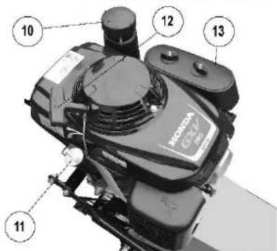
- the throttle lever is not in the STOP position.
• the fuel enters the carburettor. - the air filter is not clogged (Illustration 7-1 No. 13).
- the vent opening on the tank cap is not blocked by impurities (Illustration 7-1 No. 10).
• the spark plug can generate sparks.
If these measures do not lead to the desired result, we recommend that you contact your dealer.
Illustration 7-1: Components of the motor
EN
B. The cutting unit (line/blade) does not rotate when the mower deck safety switch bracket is actuated: (Illustration 7-2 No. 1)
- Ensure that the belt is not worn or torn.
- Ensure that the belt has not come loose from the belt pulleys.
- Ensure that the lever can tighten the belt sufficiently.
C. The cutting unit continues to rotate after the mower safety switch bracket is released: (Illustration 7-2 No. 1)
- Check whether the brake on the belt pulley is activated. If this is not the case, loosen the adjustment of the detent lever for mowing until the Ferodo pads rest on the shoulder of the pulley.
- Check whether the Ferodo lining is worn.
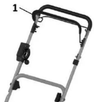
60-PRO T DRIVE

60-PRO T PUSH
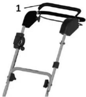
50-PRO C DRIVE
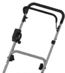
Illustration 7-2: Handle variants
D. The machine is not working properly: check:
- whether the blades/thread are not too worn (Illustration 7-3 No. 21). If the thread is worn, it should be replaced as follows:
○ Switch off the motor, remove the old thread from its seat, take a new thread, tie a simple knot in the centre (Illustration 7-4) and then insert it into its seat; - that the air filter (Illustration 7-1 No. 13) is not too clogged, which leads to a considerable loss of engine power. In this case, it must be blown out with compressed air or replaced with a new one, which you can purchase from your dealer.
• that the petrol does not run out. - that the engine oil level has not fallen below the minimum level (Illustration 7-1 No. 11).
• that none of the 4 belts are too worn. - that none of the floating blades are stuck and cause strong vibrations of the machine (Illustration 7-3 No. 21).
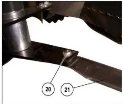
Illustration 7-3: Details of the knives
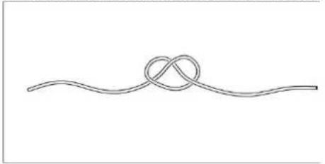
Illustration 7-4: Replacing the thread
E. The machine does not move after actuating the drive control lever:
- Change the Bowden cable setting if the Bowden cable is too loose.
- Ensure that the drive belts are not too worn.

NEVER CHANGE THE SETTINGS OF THE BOWDEN CABLES IF THE PURPOSE IS NOT KNOWN! THIS COULD IMPAIR THE CORRECT FUNCTIONING OF THE MACHINE!
8 SPARE PARTS ACCESSORIES
8.1 CUSTOMER SERVICE
All maintenance and repair work may only be carried out by specialised personnel: Contact your dealer or the nearest customer service centre. Customer service is provided by an authorised specialist dealer. For Germany, you can find your nearest authorised dealer on our homepage at www.sabo-online.com and under the "Service" / "Dealer search" tab. If you are unsure, please contact your sales partner.
8.2 SPARE PARTS
Only use original spare parts. Non-original parts can cause injury to you and other persons as well as damage to the machine. To replace machine parts, please contact your dealer or the nearest customer service centre.
9 PURPOSE OF THE OPERATING INSTRUCTIONS
These operating instructions are an integral part of the machine and are intended to provide all the information required to:
• make operators aware of the safety aspects;
- handle the packed and unpacked machine safely;
• install the machine correctly;
- correctly understand how the machines work and their limits;
• to use the machine correctly and safely;
- carry out maintenance work correctly and safely;
• dismantle the machine safely in compliance with the applicable regulations to protect the health of workers and the environment.
In accordance with the regulations in force, the managers of the company departments that purchase this machine are obliged to read the contents of this manual carefully and to ensure that the relevant operating and maintenance personnel also read the sections concerning them. The time spent on this is amply rewarded by the correct operation of the machine and its safe use.
This document assumes that the applicable health and safety regulations are observed when using the machine.
The instructions, drawings and documentation contained in this manual are of a confidential technical nature and are the strict property of ECOTECH ITALIA Srl and may not be reproduced in whole or in part.
The customer is also responsible for ensuring that only updated versions of the manual are available at the place of use in the event of changes to this document by the manufacturer.
SABO-Maschinenfabrik GmbH is exempt from any liability in the event of improper use of the machine, such as, for example
- Use contrary to specific legislation;
• Supply errors;
• serious deficiencies in maintenance;
• unauthorised modifications or interventions; - Use of non-original or non-model-specific spare parts;
- complete or partial non-compliance with the instructions;
• extraordinary events.
- improper use of the machine or use by untrained/unqualified personnel;
9.1 STORAGE OF THE OPERATING INSTRUCTIONS
The operating instructions must be kept in a safe place and must accompany the machine during its entire service life in the event of any transfer of ownership.
When storing the operating instructions, care must be taken to handle them carefully and with clean hands and not to place them on dirty surfaces. No parts may be removed, torn out or arbitrarily altered.
The operating instructions must be kept in an environment protected from moisture and heat and in the vicinity of the machine to which they refer. In the event of damage that renders the copy of the operating instructions in his possession unusable, the user can request a copy from:
stating the machine type and the serial or order number indicated on the machine's type plate.
EN
9.2 METHODOLOGY FOR UPDATING THE OPERATING INSTRUCTIONS
ECOTECH ITALIA Srl reserves the right to modify the design and optimise the machine without informing the customer and without updating the manual already supplied to the user.
However, in the event of changes to the machine installed at the customer's premises that have been agreed with the manufacturer and that result in a change to one or more chapters of the operating instructions, it is the responsibility of the manufacturer to send the affected chapters of the operating instructions with the new overall revision to the owners of the operating instructions.
It is the user's responsibility to replace the old chapters with the new ones in all copies in his possession and to replace the title page and the table of contents with those of the new revision status by following the instructions attached to the updated documentation.
SABO-Maschinenfabrik GmbH is responsible for the descriptions in German; any translations cannot be fully checked, so that in the event of discrepancies, the German language must be observed and, if necessary, our sales department contacted, which will make any changes deemed appropriate.
9.3 GLOSSARY
This section lists terms that are not commonly used or have a meaning other than the usual meaning.
The abbreviations used are explained below.
9.3.1 Glossary (Annex I p. 1.1.1 Directive 2006/42/EC)
• HAZARD: A potential source of injury or damage to health;
• HAZARDOUS AREA: Any area in and/or around a machine where the safety or health of a person is at risk;
• RISK: The combination of the probability and severity of an injury or damage to health that can occur in a hazardous situation;
• SEPARATING PROTECTION DEVICE: A machine part that provides protection by means of a physical barrier;
- NON-DISCONNECTING PROTECTIVE DEVICE: A device without a separating function which, alone or in conjunction with a separating protective device, reduces the risk;
- INTENDED USE: The use of a machine in accordance with the specifications in the operating instructions;
- REASONABLY FORESEEABLE MISUSE: The use of a machine in a manner not intended in the operating instructions, but which may result from easily foreseeable human behaviour.
9.3.2 Further definitions
• DANGEROUS PERSON: A person who is completely or partially in a danger zone;
- OPERATOR: The person or persons responsible for the installation, operation, set-up, maintenance, cleaning, repair or transport of machinery;
- QUALIFIED PERSONNEL or QUALIFIED OPERATOR: These are persons who have attended specialisation courses, training, etc. and have experience in the installation, commissioning and maintenance, repair and transport of the machine.
- HUMAN-MACHINE INTERACTION: Any situation in which an operator interacts with the machine in any of the operational phases, at any time during its operational life;
- OPERATOR QUALIFICATION: Minimum requirements for the skills that the operator must have in order to carry out the described activity;
- NUMBER OF OPERATORS: Adequate number of operators to carry out the described operation in an optimal way, resulting from a careful analysis carried out by the manufacturer, where the use of a different number of operators could lead to failure to achieve the expected result or jeopardise the safety of the personnel involved;
- MACHINE STATUS: The machine status includes the operating mode, e.g. automatic mode, standstill, etc., the status of the machine's safety devices, e.g. safety devices activated, safety devices deactivated, emergency stop switch pressed, type of insulation of the energy sources, etc;
- REST RISK: Risks that remain despite the protective measures integrated into the design of the machine and despite additional protective devices and protective measures;
- SAFETY COMPONENT: A component that is intended to fulfil a safety function and whose failure and/or malfunction endangers the safety of persons.
1 VOORWOORD 2
1.1 Algemene overwegingen....2
1.2 Operator-groepen....2
2 ALGEMENE INFORMATIE 4
II Fabbricante/The Manufacturer
ECOTECH ITALIA SRL via Dovizi 18 47122 Forlì FC - ITALIA,
is in accordance with:
• European Regulation 2006/42/EC and with the relevant national provisions;
- European Regulation 2000/14/EC and subsequent amendments, relating to the noise emission in the environment by equipment for use outdoors.
Conformity assessment was performed according the procedure laid in Annex VI of European Regulation no. 2000/14/EC. Notified Body no. 1282: Ente Certificazione Macchine S.r.L. - via Cà Bella 243, 40053 Loc. Castello di Serravalle – Valsamoggia (BO) - ITALIA.
The person authorized to compile the Technical Construction File is Mr. Roberto Romboli at ECOTECH ITALIA S.r.l. via Copernico, 85 47122 Forli FC - ITALY. The Technical Construction File required 2006/42/EC Directive is maintained at the corporate headquarters.
All of the instructions, as per the owner manual supplied with the machine, must be followed as well as all of the safety and accident prevention standards in force in the Country of use. The machine bears the CE Mark.
Data: 04/03/2023
Il Legale Rappresentante / Signature of Legal Representative
Roberto Romboli

ECOTECH ITALIA a.e.l. Via Obpomico 80-41122-FORLY FU Tel: 0548-774314 - Fax 0643 778868 Q.F. e P. NA 08994770406
| ECOTECHITALIA |
DICHIARAZIONE DI CONFORMITA' / CONFORMITY DECLARATION (All. II-A Dir. 2006/42/CE)
II Fabbricante/The Manufacturer
ECOTECH ITALIA SRL via Dovizi 18 47122 Forlì FC - ITALIA,
is in accordance with:
• European Regulation 2006/42/EC and with the relevant national provisions;
- European Regulation 2000/14/EC and subsequent amendments, relating to the noise emission in the environment by equipment for use outdoors.
Conformity assessment was performed according the procedure laid in Annex VI of European Regulation no. 2000/14/EC.
The person authorized to compile the Technical Construction File is Mr. Roberto Romboli at ECOTECH ITALIA S.r.l. via Copernico, 85 47122 Forlì FC - ITALY. The Technical Construction File required 2006/42/EC Directive is maintained at the corporate headquarters.
All of the instructions, as per the owner manual supplied with the machine, must be followed as well as all of the safety and accident prevention standards in force in the Country of use. The machine bears the CE Mark.
Data: 04/03/2023
Il Legale Rappresentante / Signature of Legal Representative Roberto Romboli


DICHIARAZIONE DI CONFORMITA' / CONFORMITY DECLARATION (All. II-A Dir. 2006/42/CE)
II Fabbricante/The Manufacturer
ECOTECH ITALIA SRL via Dovizi 18 47122 Forlì FC - ITALIA,
Is in accordance with:
• European Regulation 2006/42/EC and with the relevant national provisions;
- European Regulation 2000/14/EC and subsequent amendments, relating to the noise emission in the environment by equipment for use outdoors.
Conformity assessment was performed according the procedure laid in Annex VI of European Regulation no. 2000/14/EC.
The person authorized to compile the Technical Construction File is Mr. Roberto Romboli at ECOTECH ITALIA S.r.l. via Copernico, 85 47122 Forl FC - ITALY. The Technical Construction File required 2006/42/EC Directive is maintained at the corporate headquarters.
All of the instructions, as per the owner manual supplied with the machine, must be followed as well as all of the safety and accident prevention standards in force in the Country of use. The machine bears the CE Mark.
Data: 04/03/2023
Il Legale Rappresentante / Signature of Legal Representative
Roberto Romboli

EGOTECH ITALDA a.e.l. Via Obponledo 80-47122-FORLY FU Tel: 0548-774314 - Fax 0643 776568 Q.F. a P. NA 03994770400
Illustratie 4-2

Illustratie 4-3
4.4 VOORAFGAANDE CONTROLES

60-PRO T DRIVE

60-PRO T PUSH

50-PRO C DRIVE
5.1 ALGEMENE WAARSCHUWINGEN
7.6 DIAGNOSE EN PROBLEEMOPLOSSING
60-PRO T DRIVE

60-PRO T PUSH
50-PRO C DRIVE
Illustratie 7-2: Handgreepvarianten
II Fabbricante/The Manufacturer
ECOTECH ITALIA SRL via Dovizi 18 47122 Forlì FC - ITALIA,
is in accordance with:
• European Regulation 2006/42/EC and with the relevant national provisions;
- European Regulation 2000/14/EC and subsequent amendments, relating to the noise emission in the environment by equipment for use outdoors.
Conformity assessment was performed according the procedure laid in Annex VI of European Regulation no. 2000/14/EC.
The person authorized to compile the Technical Construction File is Mr. Roberto Romboli at ECOTECH ITALIA S.r.l. via Copernico, 85 47122 Forli FC - ITALY. The Technical Construction File required 2006/42/EC Directive is maintained at the corporate headquarters.
All of the instructions, as per the owner manual supplied with the machine, must be followed as well as all of the safety and accident prevention standards in force in the Country of use. The machine bears the CE Mark.
Data: 04/03/2023
Il Legale Rappresentante / Signature of Legal Representative Roberto Romboli

DICHIARAZIONE DI CONFORMITA' / CONFORMITY DECLARATION (All. II-A Dir. 2006/42/CE)
II Fabbricante/The Manufacturer
ECOTECH ITALIA SRL via Dovizi 18 47122 Forlì FC - ITALIA,
Is in accordance with:
• European Regulation 2006/42/EC and with the relevant national provisions;
- European Regulation 2000/14/EC and subsequent amendments, relating to the noise emission in the environment by equipment for use outdoors.
Conformity assessment was performed according the procedure laid in Annex VI of European Regulation no. 2000/14/EC.
The person authorized to compile the Technical Construction File is Mr. Roberto Romboli at ECOTECH ITALIA S.r.l. via Copernico, 85 47122 Forl FC - ITALY. The Technical Construction File required 2006/42/EC Directive is maintained at the corporate headquarters.
All of the instructions, as per the owner manual supplied with the machine, must be followed as well as all of the safety and accident prevention standards in force in the Country of use. The machine bears the CE Mark.
Data: 04/03/2023
Il Legale Rappresentante / Signature of Legal Representative
Roberto Romboli

EGOTECH ITALDA a.e.l. Via Obpomlo 80-47122-FORLF FU Tel: 0548-774314 - Fax 0643 776888 Q.F. a P. IVA 03994770400
Figura 3-3: Componentes 50-PRO C DRIVE
1 SOPORTE INTERRUPTOR DE SEGURIDAD CORTACÉSPED

Ilustración 4-2

Ilustración 4-3
4.4 CONTROLES PRELIMINARES

60-PRO T DRIVE
60-PRO T PUSH

50-PRO C DRIVE
60-PRO T DRIVE
60-PRO T PUSH
50-PRO C DRIVE
II Fabbricante/The Manufacturer
ECOTECH ITALIA SRL via Dovizi 18 47122 Forlì FC - ITALIA,
is in accordance with:
• European Regulation 2006/42/EC and with the relevant national provisions;
- European Regulation 2000/14/EC and subsequent amendments, relating to the noise emission in the environment by equipment for use outdoors.
Conformity assessment was performed according the procedure laid in Annex VI of European Regulation no. 2000/14/EC. Notified Body no. 1282: Ente Certificazione Macchine S.r.L. - via Cà Bella 243, 40053 Loc. Castello di Serravalle – Valsamoggia (BO) - ITALIA.
The person authorized to compile the Technical Construction File is Mr. Roberto Romboli at ECOTECH ITALIA S.r.l. via Copernico, 85 47122 Forli FC - ITALY. The Technical Construction File required 2006/42/EC Directive is maintained at the corporate headquarters.
All of the instructions, as per the owner manual supplied with the machine, must be followed as well as all of the safety and accident prevention standards in force in the Country of use. The machine bears the CE Mark.
Data: 04/03/2023
Il Legale Rappresentante / Signature of Legal Representative
Roberto Romboli

ECOTECH ITALIA a.e.l. Via Obpomico 80-41122-FORLY FU Tel: 0548-774314 - Fax 0543-776668 Q.F. e P. NA 08994770406
| ECOTECHITALIA |
DICHIARAZIONE DI CONFORMITA' / CONFORMITY DECLARATION (All. II-A Dir. 2006/42/CE)
II Fabbricante/The Manufacturer
ECOTECH ITALIA SRL via Dovizi 18 47122 Forlì FC - ITALIA,
is in accordance with:
• European Regulation 2006/42/EC and with the relevant national provisions;
- European Regulation 2000/14/EC and subsequent amendments, relating to the noise emission in the environment by equipment for use outdoors.
Conformity assessment was performed according the procedure laid in Annex VI of European Regulation no. 2000/14/EC.
The person authorized to compile the Technical Construction File is Mr. Roberto Romboli at ECOTECH ITALIA S.r.l. via Copernico, 85 47122 Forlì FC - ITALY. The Technical Construction File required 2006/42/EC Directive is maintained at the corporate headquarters.
All of the instructions, as per the owner manual supplied with the machine, must be followed as well as all of the safety and accident prevention standards in force in the Country of use. The machine bears the CE Mark.
Data: 04/03/2023
Il Legale Rappresentante / Signature of Legal Representative Roberto Romboli


DICHIARAZIONE DI CONFORMITA' / CONFORMITY DECLARATION (All. II-A Dir. 2006/42/CE)
II Fabbricante/The Manufacturer
ECOTECH ITALIA SRL via Dovizi 18 47122 Forlì FC - ITALIA,
Is in accordance with:
• European Regulation 2006/42/EC and with the relevant national provisions;
- European Regulation 2000/14/EC and subsequent amendments, relating to the noise emission in the environment by equipment for use outdoors.
Conformity assessment was performed according the procedure laid in Annex VI of European Regulation no. 2000/14/EC.
The person authorized to compile the Technical Construction File is Mr. Roberto Romboli at ECOTECH ITALIA S.r.l. via Copernico, 85 47122 Forl FC - ITALY. The Technical Construction File required 2006/42/EC Directive is maintained at the corporate headquarters.
All of the instructions, as per the owner manual supplied with the machine, must be followed as well as all of the safety and accident prevention standards in force in the Country of use. The machine bears the CE Mark.
Data: 04/03/2023
Il Legale Rappresentante / Signature of Legal Representative
Roberto Romboli

EGOTECH ITALDA a.e.l. Via Obponledo 80-47122-FORLY FU Tel: 0548-774314 - Fax 0643 776568 Q.F. a P. NA 03994770400
Figura 3-3: Componenti 50-PRO C DRIVE
Illustrazione 4-2

Illustrazione 4-3
4.4 CONTROLLI PRELIMINARI

60-PRO T DRIVE

60-PRO T PUSH

50-PRO C DRIVE
60-PRO T DRIVE
60-PRO T PUSH

50-PRO C DRIVE
9 OBJECTIVO DO MANUAL DE INSTRUÇÕES....18
II Fabbricante/The Manufacturer
ECOTECH ITALIA SRL via Dovizi 18 47122 Forlì FC - ITALIA,
is in accordance with:
• European Regulation 2006/42/EC and with the relevant national provisions;
- European Regulation 2000/14/EC and subsequent amendments, relating to the noise emission in the environment by equipment for use outdoors.
Conformity assessment was performed according the procedure laid in Annex VI of European Regulation no. 2000/14/EC. Notified Body no. 1282: Ente Certificazione Macchine S.r.L. - via Cà Bella 243, 40053 Loc. Castello di Serravalle – Valsamoggia (BO) - ITALIA.
The person authorized to compile the Technical Construction File is Mr. Roberto Romboli at ECOTECH ITALIA S.r.l. via Copernico, 85 47122 Forli FC - ITALY. The Technical Construction File required 2006/42/EC Directive is maintained at the corporate headquarters.
All of the instructions, as per the owner manual supplied with the machine, must be followed as well as all of the safety and accident prevention standards in force in the Country of use. The machine bears the CE Mark.
Data: 04/03/2023
Il Legale Rappresentante / Signature of Legal Representative
Roberto Romboli

ECOTECH ITALIA a.e.l. Via Obpomico 80-41122-FORLY FU Tel: 0548-774314 - Fax 0643 778868 Q.F. e P. NA 08994770406
| ECOTECHITALIA |
DICHIARAZIONE DI CONFORMITA' / CONFORMITY DECLARATION (All. II-A Dir. 2006/42/CE)
II Fabbricante/The Manufacturer
ECOTECH ITALIA SRL via Dovizi 18 47122 Forlì FC - ITALIA,
is in accordance with:
• European Regulation 2006/42/EC and with the relevant national provisions;
- European Regulation 2000/14/EC and subsequent amendments, relating to the noise emission in the environment by equipment for use outdoors.
Conformity assessment was performed according the procedure laid in Annex VI of European Regulation no. 2000/14/EC.
The person authorized to compile the Technical Construction File is Mr. Roberto Romboli at ECOTECH ITALIA S.r.l. via Copernico, 85 47122 Forlì FC - ITALY. The Technical Construction File required 2006/42/EC Directive is maintained at the corporate headquarters.
All of the instructions, as per the owner manual supplied with the machine, must be followed as well as all of the safety and accident prevention standards in force in the Country of use. The machine bears the CE Mark.
Data: 04/03/2023
Il Legale Rappresentante / Signature of Legal Representative Roberto Romboli

DICHIARAZIONE DI CONFORMITA' / CONFORMITY DECLARATION (All. II-A Dir. 2006/42/CE)
II Fabbricante/The Manufacturer
ECOTECH ITALIA SRL via Dovizi 18 47122 Forlì FC - ITALIA,
Is in accordance with:
• European Regulation 2006/42/EC and with the relevant national provisions;
- European Regulation 2000/14/EC and subsequent amendments, relating to the noise emission in the environment by equipment for use outdoors.
Conformity assessment was performed according the procedure laid in Annex VI of European Regulation no. 2000/14/EC.
The person authorized to compile the Technical Construction File is Mr. Roberto Romboli at ECOTECH ITALIA S.r.l. via Copernico, 85 47122 Forl FC - ITALY. The Technical Construction File required 2006/42/EC Directive is maintained at the corporate headquarters.
All of the instructions, as per the owner manual supplied with the machine, must be followed as well as all of the safety and accident prevention standards in force in the Country of use. The machine bears the CE Mark.
Data: 04/03/2023
Il Legale Rappresentante / Signature of Legal Representative
Roberto Romboli

EGOTECH ITALDA a.e.l. Via Obpomledo 80-47122-FORLF FU Tel: 0548-774314 - Fax 0643 776888 Q.F. a P. IVA 03994770400
Figura 3-3: Componentes 50-PRO C DRIVE
1 SUPORTE DO INTERRUPTOR DE SEGURANÇA DO CORTADOR DE RELVA
2 FERRAMENTA DE CORTE CABO BOWDEN

Ilustração 4-2

Ilustração 4-3
4.4 CONTROLOS PRELIMINARES

60-PRO T DRIVE

60-PRO T PUSH
50-PRO C DRIVE
7.4 MANUTENÇÃO CORRECTA
60-PRO T DRIVE

60-PRO T PUSH

50-PRO C DRIVE
- NEDERLANDS
- 4.4 VORABKONTROLLEN
- 2 INFORMATIONS GÉNÉRALES....4
- ILLUSTRATION 3-1 COMPOSANTS 60-PRO T DRIVE
- ILLUSTRATION 3-2 COMPOSANTS 60-PRO T PUSH
- SA711024 (50-PRO C DRIVE)
- 3.1 PRINCIPE DE FONCTIONNEMENT
- 4.1 TRANSPORT ET MANUTENTION
- 4.4 CONTRÔLES PRÉLIMINAIRES
- 2 GENERAL INFORMATION......4
- 3 DESCRIPTION OF THE MACHINE....8
- 4 INSTALLATION....10
- 5 SAFETY 12
- 6 USE OF THE MACHINE....13
- 7 MAINTENANCE 14
- 8 SPARE PARTS ACCESSORIES....17
- 9 PURPOSE OF THE OPERATING INSTRUCTIONS ....17
- EN
- 1 FOREWORD
- IMPORTANT
- 1.1 GENERAL CONSIDERATIONS
- 1.2 OPERATOR GROUPS
- 1.2.1 QUALIFICATION OF THE OPERATOR GROUPS
- 1.2.2 PICTOGRAMS
- 1.2.2.1 PICTOGRAMS FOR INFORMATION AND/OR PROCEDURES
- 1.2.2.2 PICTOGRAMS FOR OPERATOR QUALIFICATION
- 1.2.2.3 SAFETY-RELATED PICTOGRAMS
- 2 GENERAL INFORMATION
- 2.1 CHARACTERISTICS OF THE MANUFACTURER
- CUSTOMER SERVICE/SPARE PARTS
- 2.2 MACHINE IDENTIFICATION DATA AND RATING PLATES
- 2.3 EXPLANATIONS
- 2.4 SAFETY REGULATIONS
- 2.5 GUARANTEE
- 2.6 PRECAUTIONS TO BE TAKEN BY THE CUSTOMER
- 3 DESCRIPTION OF THE MACHINE
- ILLUSTRATION 3-1COMPONENTS 60-PRO T DRIVE
- ILLUSTRATION 3-2COMPONENTS 60-PRO T PUSH
- 3.1 FUNCTIONAL PRINCIPLE
- 3.1.1 INTENDED USE
- 3.2 DIMENSIONS
- TABLE 3-1: DIMENSIONS
- 3.3 AMBIENT CONDITIONS
- 3.4 LIGHTING
- 3.5 VIBRATIONS
- 3.6 NOISE EMISSIONS
- 4 INSTALLATION
- 4.1 TRANSPORT AND HANDLING
- 4.1.1 PACKAGING
- 4.2 STORAGE
- 4.3 ASSEMBLY
- 4.4 PRELIMINARY CHECKS
- BEFORE STARTING THE ENGINE
- ATTENTION!! THE MACHINE IS SUPPLIED WITHOUT ENGINE OIL
- IT IS RECOMMENDED THAT YOU ALSO FOLLOW THE INSTRUCTIONS IN THE MOTOR MANUAL
- 4.5 WASTE DISPOSAL
- 5 SAFETY
- 5.1 GENERAL WARNINGS
- 5.2 RESTRICTIONS ON USE
- 5.3 HAZARDOUS AREAS
- 5.4 SAFETY DEVICES
- 5.5 STICKER
- 5.6 RESIDUAL RISKS
- 6 USE OF THE MACHINE
- READ THE OPERATING INSTRUCTIONS CAREFULLY BEFORE STARTING UP THE MACHINE
- 6.1 SETTINGS
- 6.2 OPERATING MODES
- 6.2.1 WORKING ON A FLAT SURFACE
- 6.3 NORMAL STOPPING
- 6.4 EMERGENCY STOP
- 7 MAINTENANCE
- 7.1 MAINTENANCE STATUS
- 7.2 CLEANING
- 7.3 LUBRICATION
- 7.4 PROPER MAINTENANCE
- 7.6 DIAGNOSIS AND TROUBLESHOOTING
- THE ENGINE DOES NOT START: ENSURE THAT
- 8 SPARE PARTS ACCESSORIES
- 8.1 CUSTOMER SERVICE
- 8.2 SPARE PARTS
- 9 PURPOSE OF THE OPERATING INSTRUCTIONS
- 9.1 STORAGE OF THE OPERATING INSTRUCTIONS
- 9.2 METHODOLOGY FOR UPDATING THE OPERATING INSTRUCTIONS
- 9.3 GLOSSARY
- 9.3.1 GLOSSARY (ANNEX I P. 1.1.1 DIRECTIVE 2006/42/EC)
- 9.3.2 FURTHER DEFINITIONS
- 4.4 VOORAFGAANDE CONTROLES
- 5.1 ALGEMENE WAARSCHUWINGEN
- 7.6 DIAGNOSE EN PROBLEEMOPLOSSING
- ILLUSTRATIE 7-2: HANDGREEPVARIANTEN
- 4.4 CONTROLES PRELIMINARES
- 4.4 CONTROLLI PRELIMINARI
- 4.4 CONTROLOS PRELIMINARES
- 7.4 MANUTENÇÃO CORRECTA
Brand : SABO
Model : 60-PRO T PUSH
Category : Lawn mower