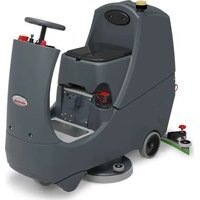
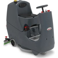
CRL8072 - Sweeper Numatic - Free user manual and instructions
Find the device manual for free CRL8072 Numatic in PDF.


| Product Type | Scrubber dryer |
| Brand | Numatic |
| Model | CRL8072 |
| Brush width | 370 mm x 2 (two brushes) |
| Brush pressure | 19.9 G/cm² |
| Cleaning area | 3600 m²/h at 5.0 km/h |
| Brush speed | 150 rpm |
| Air flow | 24.2 L/s |
| Travel speed | 0 to 6 km/h |
| Clean water tank capacity | 80 L |
| Dirty water tank capacity | 80 L |
| Brush motor | 24 V, 600 W |
| Suction motor | 24 V, 400 W |
| Drive motor | 24 V, 400 W |
| Water flow | 0 to 3.5 L/min |
| Battery power | Lithium iron phosphate (LFP), 25.6 V, 50 or 100 Ah |
| Runtime (100 Ah battery) | 2 h 40 min |
| Charging time (100 Ah) | 5 hours |
| Net weight (empty, model 8072/100) | 170.55 kg |
| Gross weight (with operator) | 325.55 kg |
| Dimensions (L x W x H) | 1460 x 948 x 1160 mm |
| Maximum slope | 11 % |
| Sound level | ≤ 70 dB(A) |
| Hand-arm vibration | ≤ 0.8 m/s² |
| Whole-body vibration | ≤ 0.45 m/s² |
| Main functions | Washing, brushing, suction, dirty water recovery |
| Maintenance | Daily draining and rinsing of tanks, cleaning filters, checking squeegees and brushes |
| Safety | Emergency stop, horn, anti-tip system, driver presence sensor |
| Spare parts and repairability | Squeegees, brushes, filters, belts, wheels, batteries available through Numatic |
Frequently Asked Questions - CRL8072 Numatic
User questions about CRL8072 Numatic
0 question about this device. Answer the ones you know or ask your own.
Ask a new question about this device
Download the instructions for your Sweeper in PDF format for free! Find your manual CRL8072 - Numatic and take your electronic device back in hand. On this page are published all the documents necessary for the use of your device. CRL8072 by Numatic.
USER MANUAL CRL8072 Numatic
EN, DE, FR, NLEN, DNER NL Numatic RT, IT, FO, PL, RT, IT, FORD
PT, IT, ES, PLPT, IT, ES, P
SV, FI, DASV, FI, DA

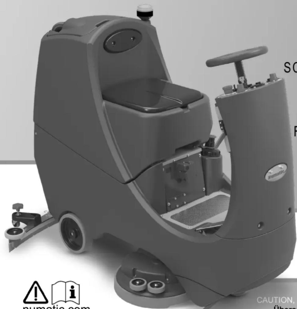
natural_image
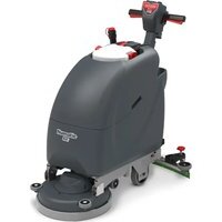
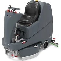
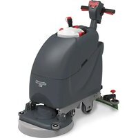
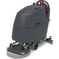
Exterior view of a Numatic cleaning service robot with visible control panel and safety warning icons (no text on main body)CRL8055/50T
CRL8072/50T
CRL8055/100T
CRL8072/100T
SCRUBBER DRYER SCHEUERSAUGMASCHINE
AUTOLAVEUSE
SCHROBZUIGMACHINE
LAVADORA-SECADORA
LAVASCIUGA PAVIMENTI
FREGADORA-SECADORA
MASZYNA CZYSZCZACA
KOMBISKURMASKIN
YHDISTELMAKONE
SKURE-OG
T∅RREMASKINE


numatic.com
Original Instructions
CAUTION, Read instructions before using the machine.
Fitting the Floor Tool ......Page 22
Lowering the Floor Tool ......Page 22
Breakaway Floor Tool ......Page 22
Raise / Lower Brush Deck......Page 28
Fitting the Brush ......Page 28
Filling the Clean Water Tank ......Page 34
Fill Level Indicator Page 34
Machine Operation
Setting the Cleaning Controls ......Page 40
Waste Water Tank Full Page 40
Emergency Stop Button / Horn...... Page 46
Anti Tip System Page 46
Machine in Use ......Page 52
Off -Aisle Cleaning Page 52
Machine Cleaning ......Pages 58 & 64
Free Wheel Function ......Page 64
Changing Floor tool Blades ......Page 70
Machine Charging ......Page 76
Battery Care Page 76
Charging Lights Sequence ......Page 82
Specifications Page 82
Trouble Shooting ......Pages 93 & 182
Rating Label / Personal Protective Equipment /
Recycling Page 104
Information for Scrubber Dryer....Pages 105-106
Recommended Spare Parts ......Page 137
Battery Information ...... Pages 149-151
Schematic Diagram Page 187
EU Declaration Document ......Page 188
Company Address ......Page 192
CRL8055/50T = 1x battery
CRL8055/100T = 2x batteries
CRL8072/50T = 1x battery
CRL8072/100T = 2x batteries
DE
CRL8072/100T = 2x batterien
FR
CRL8055/100T = 2x batteries
CRL8072/100T = 2x batteries
NL
CRL8055/50T = 1x accu
CRL8055/100T = 2x accu's
CRL8072/50T = 1x accu
CRL8072/100T = 2x accu's
PT
CRL8055/50T = 1x bateria
CRL8055/100T = 2x baterias
CRL8072/50T = 1x bateria
CRL8072/100T = 2x baterias
IT
CRL8055/100T = 2x batteries
CRL8072/50T = 1x akumulator
CRL8072/100T = 2x batteries
SV
CRL8055/50T = 1x batteri
CRL8055/100T = 2x batterier
CRL8072/50T = 1x batteri
CRL8072/100T = 2x batterier
FI
CRL8055/50T = 1x akun
CRL8055/100T = 2x akut
CRL8072/50T = 1x akun
CRL8072/100T = 2x akut
DA
CRL8055/50T = 1x batteri
CRL8055/100T = 2x batterier
CRL8072/50T = 1x batteri
CRL8072/100T = 2x batterier
PLEASE READ, BEFORE COMMENCING OPERATION
EN
After the removal of all the packaging, carefully open and check the contents.
- Owner Manual • 2 x Ignition Keys • Battery Charging Lead • 1 x 30 Amp Fuse (Brush) • 1 x 20 Amp Fuse (Vac)
- 1 x 10 Amp Fuse • 1 x 4 Amp Fuse • 1 x 2.5 Amp Fuse • Maxi Fuse-puller
| 1 Operator control panel | |
| 2 Brush deck foot pedal | |
| 3 Anti-tip buffers | |
| 4 Floor-tool raise / lower lever | |
| 5 Clean water tank fill point | |
| 6 Brush deck | |
| 7 | Fuse Panel (20A Vac / 30A Brush Motor / 4A Water pump / 10A Brush engage). |
| 8 Li-ion batteries | |
| 9 Clean water tank filter | |
| 10 On-board charger and charge indicator | |
| 11 Accelerator pedal | |
| 12 Pedestrian warning light | |
| 13 Floor-tool transit bracket | |
| 14 Air separator assembly | |
| 15 Waste water emptying hose | |
| 16 Vacuum hose | |
| 17 Clean water tank emptying hose | |
| 18 Floor-tool | |
| 19 Safety Fuse (2.5A) | |
DE
EN: In the event of a breakdown contact your Numatic dealer.
| 1 Water Flow Rate 6 Forward / Reverse Switch | ||
| 2 Vacuum On/Off Switch 7 Traction LED | ||
| 3 Brush Engage Button 8 Emergency Stop Button | ||
| 4 Horn Button 9 Maximum Speed Control | ||
| 5 Hours and Battery Meter Display 10 Key Ignition Switch |
DE
- Owner Manual
- Battery Charging Lead
- 2 x Keys
- 30 Amp Fuse
- 20 Amp Fuse
- 1 x 10 Amp Fuse
- 1 x 4 Amp Fuse
- 2.5 Amp Fuse
- Maxi Fuse Puller
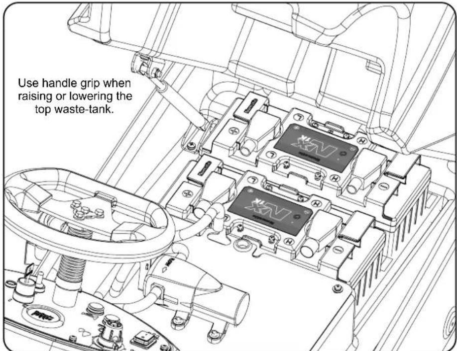
Lift top tank assembly to reveal battery compartment, ensuring you use the handle grip provided.
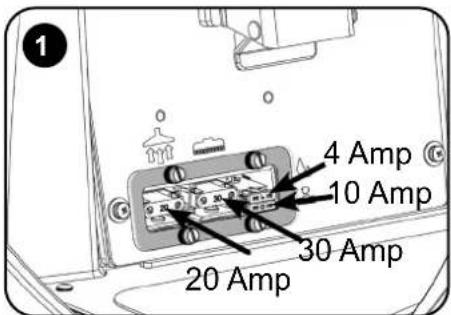
Fit vacuum and brush fuses (contained in start-up pack) into the fuse holders as illustrated.
(Fig. 1)
Charge the machine to activate the batteries. After the batteries were activated, LEDs should illuminate on the top of all the batteries.
Insert Key into ignition located on the control panel (See (Fig. A)
Numatic International Ltd recommends ONLY using 911948 NX1K LFP battery type Lithium Batteries provided with this machine.
20 Amp Fuse = Vac Motor
30 Amp Fuse = Brush Motor
10 Amp Fuse = Brush Engage
4 Amp Fuse = Water Pump
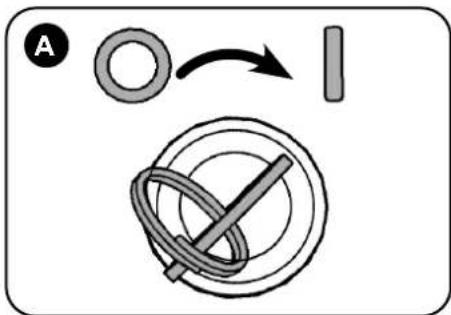
Insert the Ignition key and switch the machine on. (Fig. A)

ENSURE THAT NO METAL OBJECTS COME INTO CONTACT WITH BATTERY TERMINALS WHILE THE BATTERIES ARE EXPOSED.

natural_image
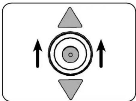
Abstract diagram with concentric circles and directional arrows, no text or symbols presentTurn the key to switch on the machine, set lever to forward.
natural_image
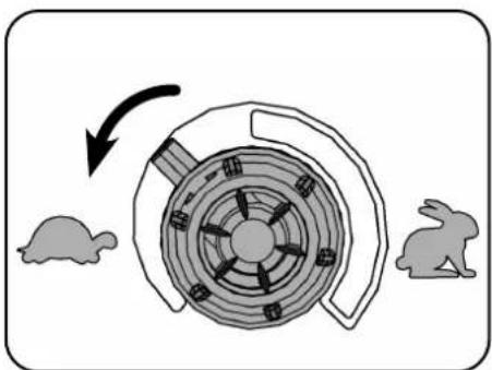
Diagram showing a spiral shell with internal components and two rabbits nearby (no text or symbols)Set to slowest speed, depress accelerator and drive off the pallet using ramp provided.
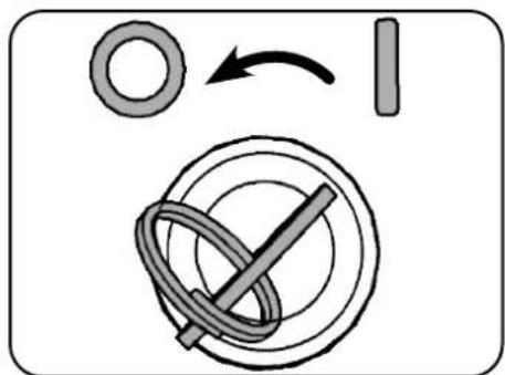
Once in a safe location switch off machine.
Note: DO NOT depress accelerator pedal while software initialises. The machine will not operate in reverse with the floor tool lowered. The seat is fitted with a pressure sensor that disables the machine until an operator is seated.
DE
4 A-sikring = Vandpumpe
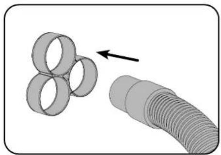
Fitting the Hose Guide
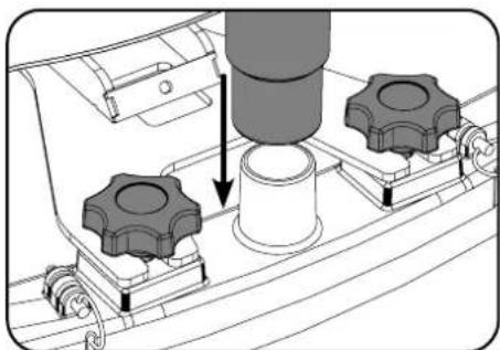
The U-bend in the hose prevents water spillage when the vacuum is switched off. Refit vacuum hose to the floor tool when finished.
natural_image
Diagram showing a coiled tube being inserted into a threaded tube, with an arrow indicating direction (no text or symbols present)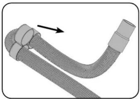
natural_image
Illustration of a flexible hose with a curved tube and connectors, showing a directional arrow (no text or symbols)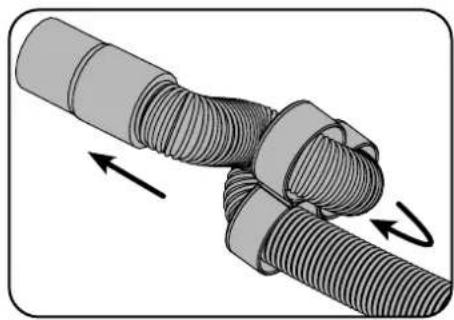
natural_image
Diagram of a mechanical joint or connector with threaded ends and directional arrows indicating movement (no text or symbols)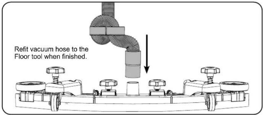
Note: DO NOT push the vacuum hose onto the floor tool with the floor tool in the raised position.
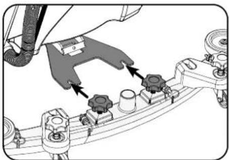
Fitting the Floor Tool
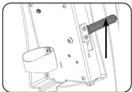
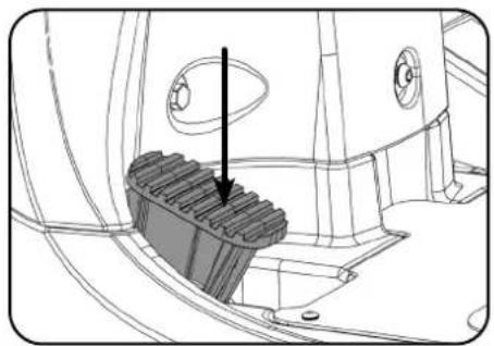
Note: Raise floor tool before driving to the cleaning area. The machine will not operate in reverse with the floor tool lowered.
Break-away Floor Tool
The floor tool design incorporates a safety knock-off feature, this allows it to safely disengage from its mounting should it become caught on an obstruction during forward movement.
Make sure you do not over tighten the retaining knobs.
natural_image
Technical diagram of a mechanical assembly with labeled components and an arrow indicating direction (no text or symbols present)Lower the floor tool.
natural_image
Mechanical assembly diagram showing a hand connecting components to a vehicle chassis (no text or labels visible)Slide floor tool onto bracket. Tighten retaining knobs to finger tight and attach hose.
natural_image
Mechanical assembly diagram showing a cylindrical component being inserted into a housing with two gear-like components (no text or symbols visible)
natural_image
Technical line drawing of a mechanical assembly with a tool and component (no text or symbols)Raise the floor tool.
DE
Raise Brush Deck/ Fitting the Brush/ Lower Brush Deck

Always ensure that the machine is switched off before making any adjustments.

natural_image
Technical line drawing of a mechanical component with a highlighted internal structure and an arrow indicating direction (no text or symbols present)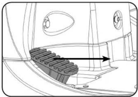
natural_image
Technical line drawing of a mechanical gear assembly with no visible text or symbols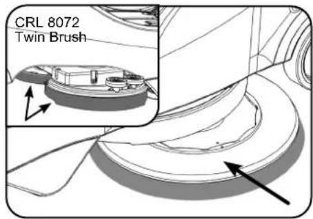
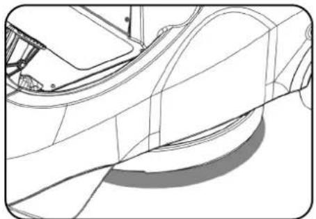
Raise brush deck. Brush deck raised position. Slide brush under machine.
natural_image
Technical line drawing of a car's front wheel and side panel (no text or symbols)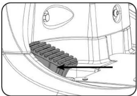
natural_image
Technical line drawing of a mechanical component with a gear-like structure and mounting holes (no text or symbols)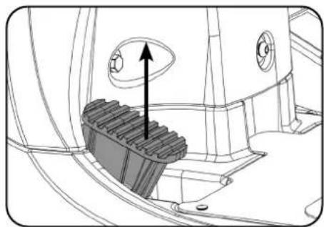
natural_image
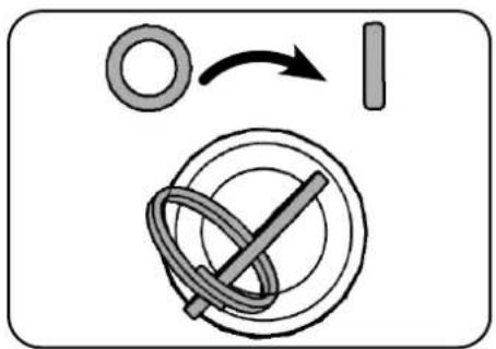
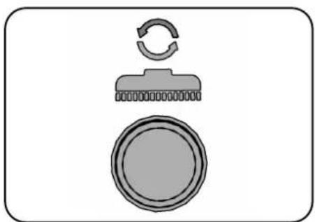
Technical diagram of a mechanical component with a gear-like base and directional arrow (no text or symbols)Brush in place. Lower brush deck. Brush deck lowered.
natural_image
Diagram of a mechanical component with a circular base and a curved top section (no text or symbols)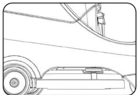
natural_image
Technical line drawing of a mechanical assembly with rollers and guide rails (no text or symbols)Press and hold brush engage button. Switch machine on. Machine has picked up the brush.
When fitting the brushes make sure it is done on a flat surface.
Please follow the same process to fit both brushes to the CRL8072T as is for the single brush fitting on the CRL8055T.
To disengage the brush, remove manually.
Note: Do not lift the brush deck until the brush has stopped revolving or the brush will release.
Make sure you raise the brush deck before driving to the cleaning site.
Safety Gloves are recommended for the changing of used brushes.
Floor Tool Transit Bracket
When in transit, the floor tool can be placed on the bracket at the rear of the machine. Simply slot the retaining knob into the bracket.
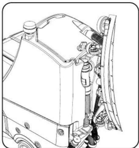
natural_image
Technical line drawing of a mechanical assembly with hoses and components (no text or symbols)Always ensure that the machine is switched off before making any adjustments.

Filling the Clean Water Tank
The CRL 8055/8072 is equipped with a large capacity 80 litre clean water tank, allowing for large areas to be covered in a single fill.
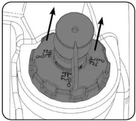
natural_image
Mechanical component diagram showing a central hub with two directional arrows indicating motion or force (no text or symbols present)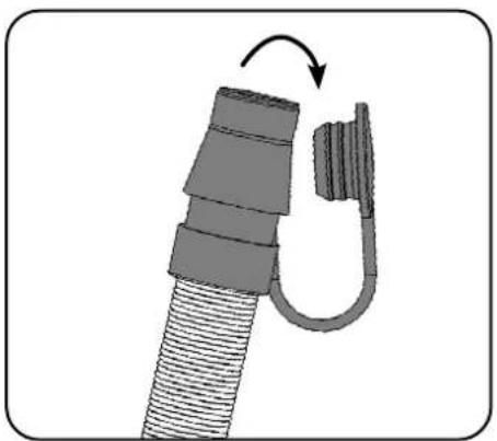
natural_image
Diagram of a mechanical component with a curved arm and threaded shaft, showing a rotation arrow (no text or symbols)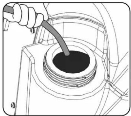
natural_image
Technical line drawing of a mechanical component with a tool inserted into a circular opening (no text or symbols)To fill clean water tank, extend fill hose. Remove rubber seal and fill. Alternatively remove filler cap completely.
Note: Great care must be taken to ensure that contaminants (leaves, hair, dirt, etc.) are not allowed to enter the clean water tank during the filling process. If using a bucket or similar, ensure it is always clean and free from debris.
Fill Level Indicator
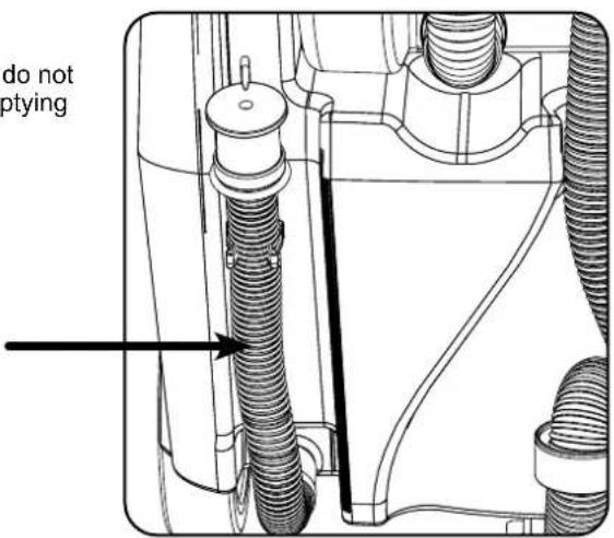
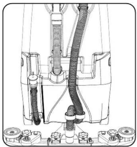
When filling the clean water tank, do not fill above the clean water tank emptying hose retaining clip.
This can be found at the rear of the machine.
natural_image
Technical line drawing of a mechanical device with hoses and connectors (no text or symbols)
If you need to access the batteries, make sure that the waste water tank is empty before lifting.

DE
EN Machine Operation

IMPORTANT
Do not operate machine unless the operator manual has been read and fully understood.

Drive the machine to the cleaning site.
Before cleaning operation, place out appropriate warning signs and sweep or dust-mop the floor.
When ready for cleaning lower the floor tool (page 6) and the brush deck (page 7).
Setting the Cleaning Controls
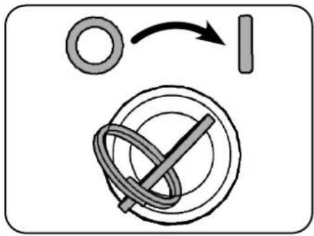
Switch machine on. Battery charge-level indicator illuminates.
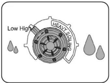
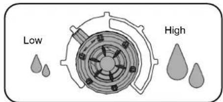
Set the water flow rate as required. Switch the vacuum motor on.

natural_image
Diagram of a door with three upward arrows below indicating movement or force (no text or symbols)Waste Water Tank Full
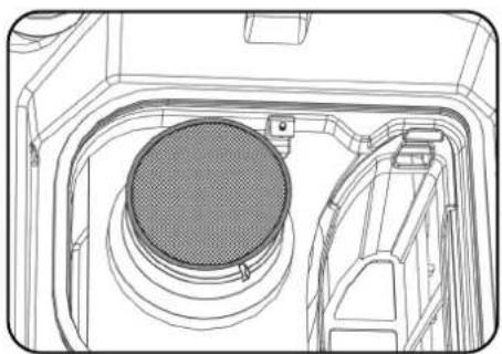
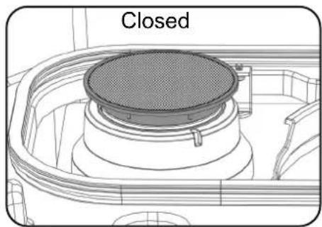
The vac shut off system stops the airflow when the top waste water tank is full.
The vac motor will continue to run, there is an audible difference in the sound when the shut off system operates.
For more details on checking and cleaning the shut off system see page 13.
natural_image
Technical line drawing of a mechanical component with a circular component and internal structure (no text or symbols)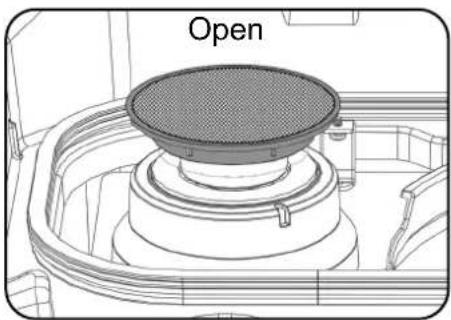
natural_image
Technical line drawing of a mechanical component with a labeled 'Open' section (no other text or symbols)Offen/ Ouvert/ Open/ Aberto/ Aperto/ Abierto/ Otwarty/ Öppen/ Avoinna/ Åben
natural_image
Technical line drawing of a mechanical component with a circular top and curved base (no text or symbols)Geschlossen/ Fermé/ Dicht/ Fechado/ Chiuso/ Cerrado/ Zamknięty/ Stängd/ Suljettu/ Lukket

Always ensure that the floor is pre-swept and relevant safety signs are displayed.

DE
Vuilwatertank is vol
EN Machine Operation
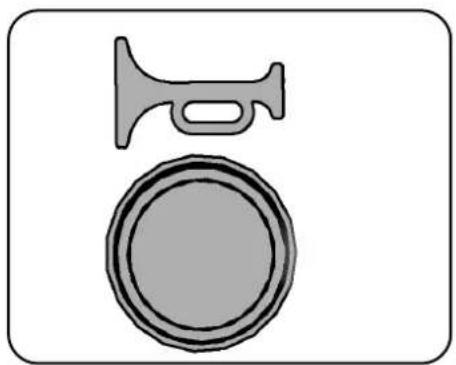
Emergency Stop Button/ Horn
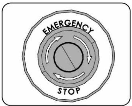
In an emergency, strike the emergency stop to disable the machine.
natural_image
Simple line drawing of a hammer and a circular object (no text or symbols)Horn button - for sounding a warning signal
Note: After the Emergency Stop button has been pressed the Traction LED will flash 7 times, pause and repeat until the Emergency Stop button has been reset and the machine switched off / on.
Maximum Speed Control
Set desired traction speed as required, depending on floor type and level of soiling.
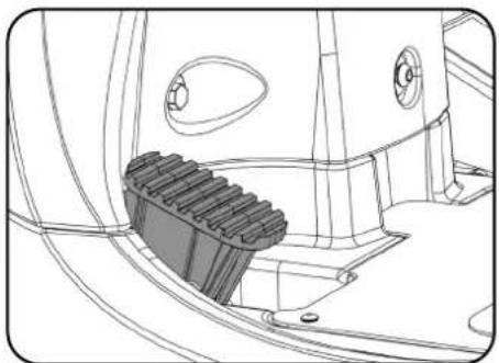
Once the Max speed has been set using the control knob on the control panel, fine adjustments can be made using the variable control speed pedal located on the right side of the footplate.
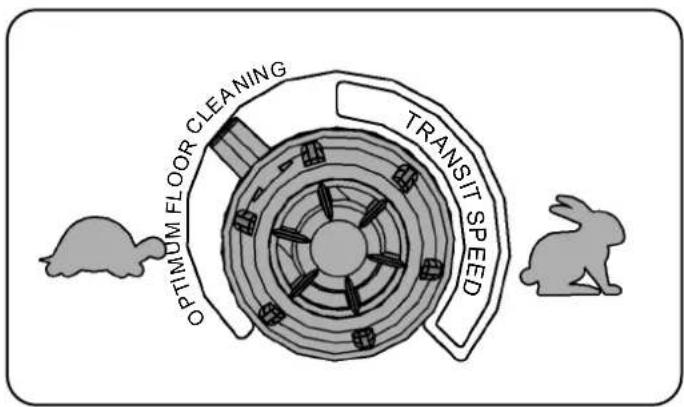

Care must be taken to reduce speed when cornering or manoeuvring.

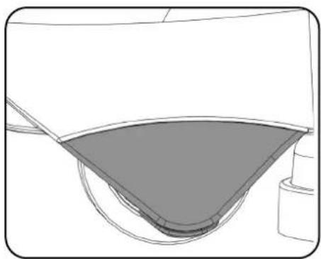
Anti-tip System
The CRL 8055/8072 is equipped with an Anti-tip system.
The machine automatically slows down preventing the machine from tipping over if cornering at speed.
The buffers at the front are designed to prevent the machine tipping in the event of the operator turning sharply.
The buffers are designed to be replaceable when worn.
natural_image
Pure technical line drawing of a mechanical component or bracket (no text or symbols)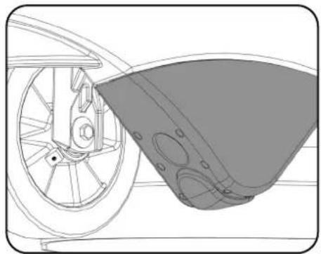
natural_image
Technical line drawing of a bicycle wheel and adjacent mechanical component (no text or symbols)DE
EN Machine Operation

Do not operate the machine on inclines that exceed 11%.

Machine in Use

natural_image
Abstract diagram with concentric circles and directional arrows, no text or symbols presentSet lever to forward.
To operate, select forward and depress the accelerator pedal.
Note: The machine will not operate in reverse with the floor tool lowered.
Vacuum pick-up and water flow will turn on if selected and providing the brush and floor tool are in the lowered position, the machine will move forward.
Clean water is dispersed evenly via 'THRU-FEED' scrubbing brushes.
The waste water is then retrieved by the suction floor tool.
Overlap each scrubbing path by 10cm to ensure an even clean.
After stopping, let the vacuum motor run for 10 seconds to collect any water left in the vacuum hose, then switch the vacuum motor off.
On heavily soiled floors use a 'double scrub' technique.
First pre-scrub the floor with the floor tool in the raised position, allow the chemicals time to work, then scrub the area a second time with the floor tool lowered.
If your machine leaves streaks on the cleaned floor, either clean the floor tool blade or adjust blade height for optimum performance.
natural_image
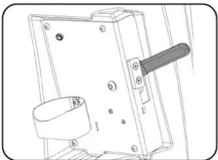
Technical line drawing of a mechanical component with gear and mounting holes (no text or symbols)Brush deck in lowered position. Floor tool lever in lowered position.
natural_image
Technical line drawing of a mechanical switch or bracket assembly (no text or symbols)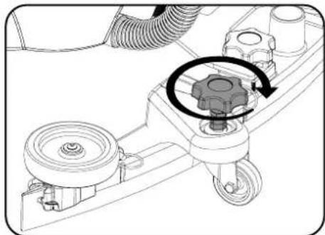
natural_image
Mechanical assembly diagram showing a gear mechanism with rotating components (no text or labels)Adjusting the blade height.
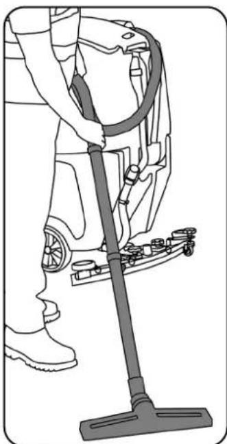
Off-aisle Cleaning Kit
(Optional Extra Accessory) 606182
The optional off-aisle cleaning kit gives added flexibility to the operator.
The kit can be used to clean hard to reach / inaccessible areas.
Remove the vacuum hose from the floor tool and attach to the off-aisle kit.
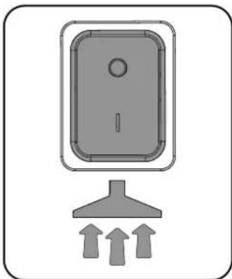
To operate the vacuum, press the vacuum switch on.
Note: Return the hose to the floor tool once finished using the off-aisle facility.
natural_image
Diagram of a door with three upward arrows below indicating pressure or force (no text or symbols)Vacuum switch.
Saugtaster/ Bouton de l'aspirateur/ Stofzuigerschakelaar/ Interruptor de vácuo/ Interruttore aspiratore/ Interruptor de aspiración/ Włącznik ssania/ Dammsugaromkopplare/ Alipainekytkin/ Vakuumkontakt
natural_image
Line drawing of a person using a vacuum cleaner on a vehicle (no text or symbols)Overlap hver skrubberute med 10 cm for at sikre jævn rengøring.
Always ensure that the machine is switched off prior to any maintenance.

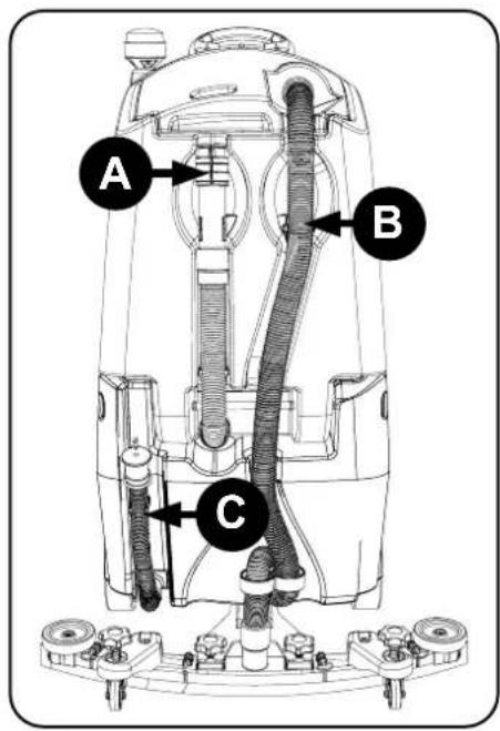
After use, empty waste water tank using emptying hose and flush-out with clean water.
Remove floor tool vacuum hose ensuring you remove the U-bend clip and flush out with clean water.
C Empty clean water tank, using emptying hose and again flush out with clean water.
natural_image
Technical diagram of a vehicle engine component with hoses and valve (no text or labels)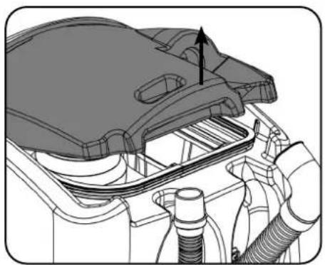
natural_image
Technical illustration of a mechanical assembly with pipes and housing (no text or symbols)Remove hose. Remove separator and clean.
natural_image
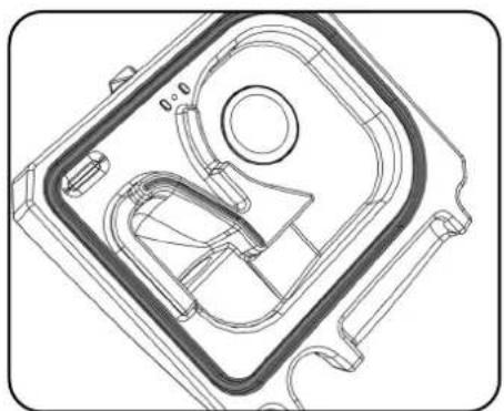
Technical line drawing of a mechanical component with no visible text or symbolsClean and examine rubber seal during each clean.
natural_image
Technical line drawing of a mechanical assembly with hoses and components (no text or symbols)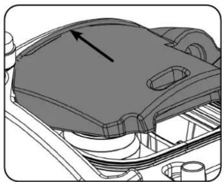
natural_image
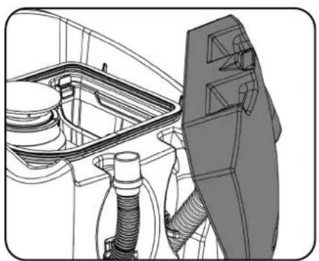
Technical line drawing of a mechanical component with an arrow indicating direction (no text or symbols present)Note: The separator can be hung from either side of the top tank while you maintain the machine using the clip on the front of the lid.
When refitting the separator make sure you engage the front of the separator BEFORE pushing the separator down.
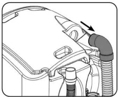
Refit the vacuum hose.
DE
Always ensure that the machine is switched off prior to any maintenance.

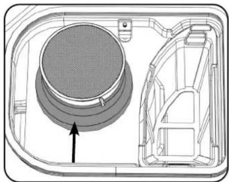
Located in your waste water top tank is a vacuum shut off system, this prevents suction when the waste water tank is full. It also prevents foam created by high-foaming detergents from entering the motor. Sometimes the float vents get clogged and blocked, clean to ensure correct operation. Regularly check and clean the air filter in the top of the assembly. Remove debris basket filter and rinse using clean water, and refit.
IMPORTANT: If the debris basket is allowed to become clogged, vacuum performance can deteriorate.
natural_image
Technical diagram of a mechanical component with internal structure and an arrow indicating direction (no text or symbols)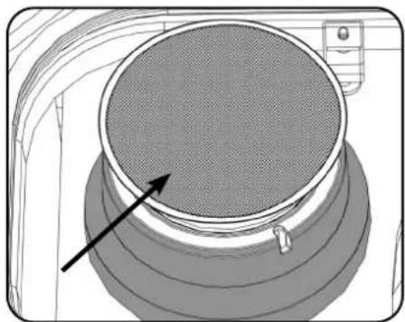
natural_image
Diagram of a circular fan or filter component with concentric rings and a pointer arrow, no text or symbols present.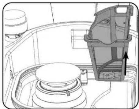
natural_image
Technical line drawing of a mechanical assembly with a highlighted component (no text or symbols)Debris basket removal.Float vent. Air filter
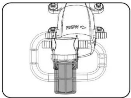
The clean water tank filter is located to the front of the battery compartment and should be checked at regular intervals.
Lift the filter off of the cradle, unscrew the bottom and remove, taking care not to spill any liquid on to the batteries.
Rinse using clean water and refit, refitting is reversal of removal.
Note: Any Spills should be wiped up before tank is lowered.
natural_image
Technical line drawing of a mechanical component with no visible text or symbols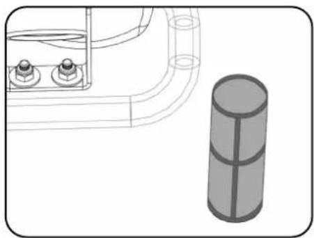
natural_image
Technical line drawing of a mechanical component with a cylindrical part beside it (no text or symbols)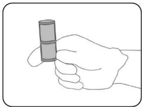
natural_image
Line drawing of a hand holding a cylindrical object (no text or symbols)Free Wheel Function

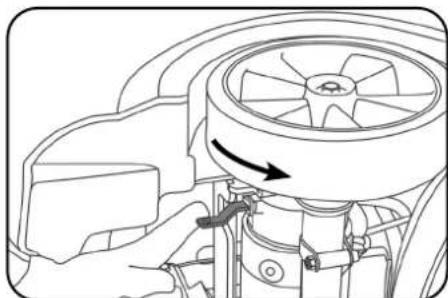
The CRL 8055/8072 is equipped with a free wheel function that will enable the operator to move the machine.
The free wheel lever can be found on the right hand side of the rear axle.
To disengage the brake, pull the lever into the down position.
Re-engage the brake by moving the lever into the up position.
Note: When the brake is disengaged the machine has no braking facility.
Care must be taken when moving the machine in free wheel mode.
natural_image
Technical line drawing of a mechanical component with an arrow indicating direction (no text or symbols)Machine shown on it's side.
DE
Always ensure that the machine is switched off prior to maintenance.

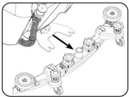
Lower the floor tool then unscrew the retaining knobs and slide it off the holding bracket.
Rinse the floor tool assembly with clean water and refit.
natural_image
Mechanical assembly diagram showing a component being inserted into a bracket (no text or labels visible)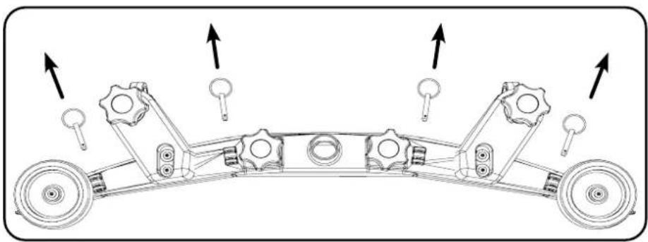
natural_image
Mechanical assembly diagram showing a vehicle chassis with gears and wheels, no text or symbols presentRemove floor tool. Remove four retaining pins.
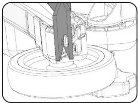
natural_image
Technical line drawing of a mechanical assembly with no visible text or symbols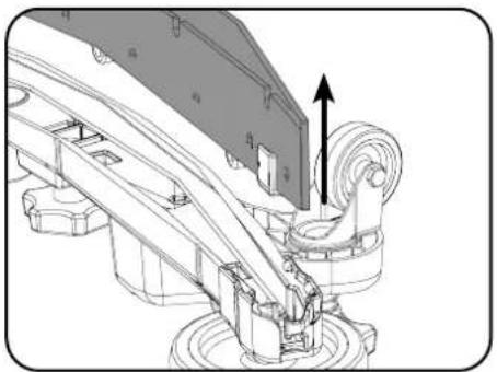
natural_image
Mechanical assembly diagram showing a lever mechanism with motion arrows (no text or symbols)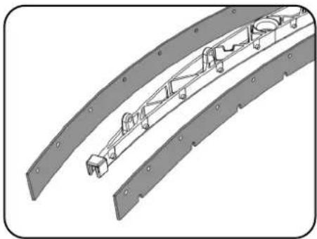
natural_image
Technical illustration of a mechanical assembly with curved brackets and mounting holes (no text or symbols)Turn the floor tool over. Separate the blade from the carrier. Peel away blades.
Periodically the floor tool blades should be examined and checked for wear and damage.
Replacement is a reversal of the removal process.
Floor Tool Overview
- Retaining pins x 4
- Front blade (slotted)
- Blade carrier
- Rear blade
- Floor tool main body
Note: The blades are designed to be reversible, thus extending their useful working life.
DE
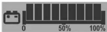
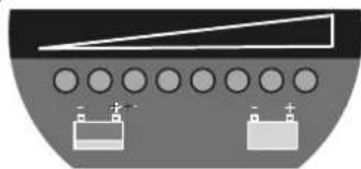
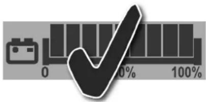
The battery meter displays the charge level of the batteries; when fully charged, all meter lights are illuminated.
1
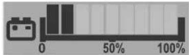
As the machine is used and the batteries are discharged, the meter lights will go out from right to left.
If the battery-charge level is allowed to discharge to the point that only one or two lights / bars remain illuminated, the operator must consider charging the machine.
bar
| Category | Value (%) | |---|---| | Bar 1 | 50 | | Bar 2 | 50 |2

Always ensure that the machine is switched off prior to charging.

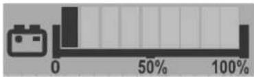
When the machine is getting close to empty the last light starts to flash, the operator should then take the machine to a suitable charging point. When the battery icon starts flashing, the vacuum and brush motors will be disabled and the user should charge the machine.
bar
| Category | Value (%) | |---|---| | Bar at 0 | 50 | | Bar at 100 | 100 |3
natural_image
Diagram of a ship's deck with circular components and a triangular structure (no text or symbols)Alternative Display When the last red light starts flashing, the vacuum and brush motors will be disabled and the user should charge the machine.
The LFP batteries are sealed for life and are totally maintenance free.
The on-board charger automatically monitors the charging process and will switch to float charge mode when the batteries are fully charged. Float charge mode allows to maintenance LFP batteries at the right level of health. The machine should be left on float charge overnight or over the weekend at least once per month or more frequently if needed.
Insert the charging lead required for your country into the charging point.
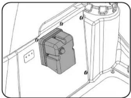
The machine charging point is located to the rear of the machine under the control panel.
Connect to a suitable power supply.
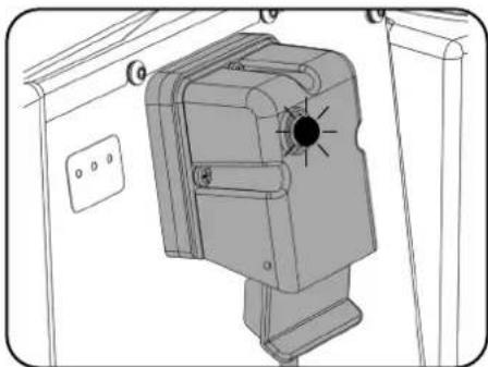
Once mains power is connected the red charging indicator will illuminate.
To ensure a full charge, from an empty state, the machine should be left for a period of 8 hrs.
Once fully charged, disconnect the charging lead from both the power supply and the machine.
natural_image
Technical line drawing of a mechanical assembly with a central component and mounting bracket (no text or symbols)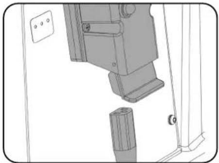
natural_image
Technical line drawing of a mechanical assembly with no visible text or symbolsMachine charging point, above footplate. Insert country specific charging lead.
natural_image
Technical line drawing of a mechanical device with a circular component and mounting base (no text or symbols)Red charging indicator illuminates when charging.
Battery Care

To ensure your machine remains at its maximum efficiency and prolong your battery life, please follow the simple steps below:

Under normal daily usage:
Re-charge the machine FULLY after each use regardless of machine operation time.
It is recommended to leave the machine connected to power grid overnight, at least once a month. If the user does not disconnect the cable after full charge it is not an issue.
Do not leave the machine in a discharged state.
Periodically inspect the battery connections for tightness and corrosion.

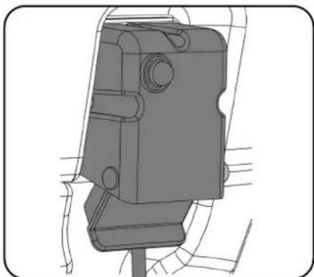
natural_image
Technical line drawing of a mechanical component with no visible text or symbols
der Maschine
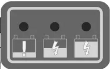
| Signal (LED) Meaning | ||||
| Red LED on First Phase (Constant Current Mode). | ||||
| Orange LED on Second Phase (Constant Voltage Mode). | ||||
| Green LED on | Third Phase (Constant Voltage Mode) Charge Complete.However, after full re-charge, leaving the charger connected moves to float-charge mode to help to maintain a healthy balance between batteries. | |||
| Red LED flashing followed by Pause | Cooling Fan Locked > 1 flash between pause.Over Voltage Protection / Output Short Circuit / Battery Reverse Polarity > 2 flashes between pause.Over Temperature Protection > 3 flashes between pause.Charge Time has exceeded 16 hrs during phase 1 or 2 > 4 flashes between pause. | |||
| Condition RED LED YELLOW LED GREEN LED | ||||
| Pre-charge Timeout | Flashing 4 Times | O | ||
| CC Timeout | O | |||
| CV Timeout | O | O | ||
| Battery Disconnection | ||||
| Note: O means illuminates continuously | ||||
natural_image
Three battery icons with warning symbols, no text or labels present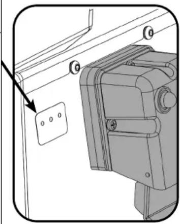
natural_image
Technical diagram of a mechanical assembly with mounting holes and a wall-mounted component (no text or symbols)Note: Re-charge the machine fully after its last use. Do not leave the machine in a discharged state.
Under abnormal use;
i.e. leaving the machine without charging for a period of time, we advise that you follow these steps:
Float charge mode allows to maintenance LFP batteries at the right level of health.
The machine should be left on float charge overnight or over the weekend at least once per month.
Charge fully the day before you start using the machine again.
Specifications
| Model - CRL 8055 / 8072 | |||||||||||
| (Empty) Net Weight Brush | Weight Brush | Width | Brush Pressure | Pad Width | Pad Pressure | Cleaning Area | |||||
| CRL8055/50 - 139.75 kg | 17 kg 550 | mm 8.4 G/cm | ^2 | 508 mm 6.8 | G/cm ^2 | 2750m ^2 @ 5.0 Km/Hr | |||||
| CRL8055/100 - 150.55 kg | |||||||||||
| CRL8072/50 - 159.75 kg | 32 kg 370m | mm x 2 19.9 G/cm | ^2 | 360mm x 2 16 | .6 G/cm ^2 | 3600m ^2 @ 5.0 Km/Hr | |||||
| CRL8072/100 - 170.55 kg | |||||||||||
| Transaxle Run | Time | Total Battery Weight | Charge Times Height | Length | Width | ||||||
| 24 V / 400 W | 50Ah -1 Hr 20 Mins | 10.8 kg | 2.5 Hrs | 1160 mm | CRL 8055 -1460 mmCRL 8072 -1450 mm | CRL 8055 -805 mmCRL 8072 -948 mm | |||||
| 100Ah -2 Hr 40 Mins | 21.6 kg | 5 Hrs | |||||||||
| Brush Speed | Airflow | Transit Speed | Capacity | Brush Motor | Vac Motor | Water Flow Rate | Sound Pressure | ||||
| 150 r/min | 24.2 L/sec | 0-6 km/h | 80L / 80L | 24 V600 W | 24 V400 W | 0 - 3.5L/min | ≤ 70dB (A) | ||||
| RTU / Gross Weight + 75Kg Operator | Hand Arm Vibration | Whole Body Vibration | Max Gradient | ||||||||
| CRL8055/50 = 293.75 Kg | ah≤0.8m/s ^2 | aw≤0.45m/s ^2 | 11% | ||||||||
| CRL8055/100 = 305.55 Kg | |||||||||||
| CRL8072/50 = 314.75 Kg | |||||||||||
| CRL8072/100 = 325.55 Kg | |||||||||||
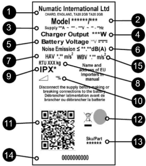
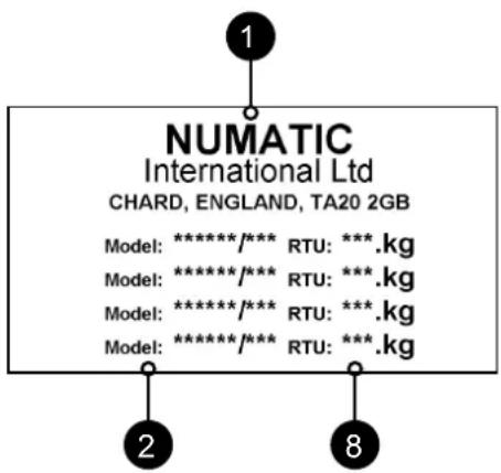
| Rating Label | |
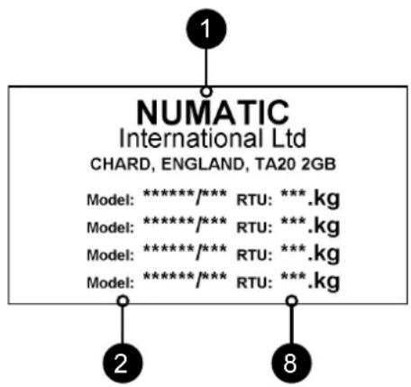
| 1 Company Name & Address | |
| 2 Machine Description | |
| 3 | Supply Current / Voltage / Alternating Current / Frequency |
| 4 Charger Output | |
| 5 Battery Voltage | |
| 6 Noise Rating | |
| 7 Hand Arm Vibration | |
| 8 Weight (ready to use) | |
| 9 Ingress Protection Rating | |
| 10 Max Gradient | |
| 11 QR Code | |
| 12 WEEE Logo / Approvals Mark | |
| 13 SKU / Part | |
| 14 Machine yr/wk Serial number | |
| 15 Whole Body Vibration | |
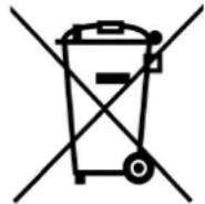
WEEE (Waste, Electrical and Electronic Equipment)
Scrubber dryer Accessories and packaging should be sorted for environmentally-friendly recycling.
Only for UK & EU countries.
Do not dispose of scrubber-dryer into household waste.
According to the European Directive 2012/19/EU on waste electrical electronic equipment and its incorporation into national law.
Scrubber-dryers that are no longer suitable for use must be separated, collected and sent for recovery in an environmentally-friendly manner.
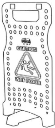
PPE (Personal protective equipment) that may be required for certain operations.
 |  |  |  |  |
| Ear Protection Safety | Footwear Head Protection | Safety Gloves | ||
 |  |  |  | |
| Dust / Allergens Protection | Eye Protection Protective | Clothing | Hi-Vis Jacket | CautionWet Floor Sign |
Note: A risk assessment should be conducted to determine which PPE should be worn.
Safety Critical Component:
Charging Leads: H05VV-F 3 Core x 1.0 mm²
Battery Charger: 100V-240V (50-60Hz)
DC Output: 25.6VDC, 20A
In the event of a breakdown contact
your Numatic dealer or the
Numatic Technical
help line +44 (0)1460 269268
EN Information for Scrubber Dryer

READ MANUAL BEFORE USE
COMPONENT INTERVAL INSPECT FOR
| Charging Lead DAILY Scuffi ng | cracks, splits, conductors showing | |
| Brushes DAILY Bristle damage | wear, drive collar wear | |
| Squeegee Blade BEFORE EACH USE | Wear, cracks, splits | |
| Filters BEFORE EACH USE | Clogging and debris retention | |
| Tanks AFTER EACH USE | Rinse dirty water tank after use |

As with all electrical equipment care and attention must be exercised at all times during its use, in addition to ensuring that routine and preventative maintenance is carried out periodically in order to ensure its safe operation. Operators shall be adequately instructed on the use of these machines.
WARNING
Failure to carry out maintenance as necessary, including the replacement of parts to the correct standard could render this equipment unsafe and the manufacturer can accept no responsibility or liability in this respect.
When ordering spare parts always quote the Model Number / Serial Number specified on the Rating Plate.
Do not use on cleaning surfaces having a gradient exceeding that marked on the machine. While on ramps or inclines, avoid sudden stops. Avoid sharp turns. Use low speed down ramps. Clean only while descending (driving down) the ramp.
This machine is not intended for use by persons (including children) with reduced physical, sensory or mental capabilities, or lack of experience and knowledge.
Children should be supervised to ensure that they do not play with the appliance.
Only use brushes provided with the appliance or those specified in the instruction manual.
The use of other brushes may impair safety.
A full range of brushes and accessories are available for this product.
Only use brushes or pads which are suitable for the correct operation of the machine for the specific task being performed.
It is essential that this equipment is correctly assembled and operated in accordance with current safety regulations.
When using the equipment always ensure that all necessary precautions are taken to guarantee the safety of the operator and any other persons who may be affected.
Wear non slip footwear when scrubbing. Use a respiratory mask in dusty environments.
When cleaning, servicing or maintaining the machine, replacing parts or converting to another function the power source shall be switched off.
Mains operated machines shall be disconnected by removing the power plug, and battery operated machines shall be disconnected by using top ON/OFF button on the battery.
In order to prevent unauthorised use of the machine the power key must be removed after use.
Machines left unattended shall be secured against unintentional movement.
When detergents or other liquids are used, read the manufacturer's instructions.

CAUTION
This machine is not suitable for picking-up hazardous dust.
This machine is not to be stored outdoors or in wet conditions.
This machine is for indoor use only.
NOTES: This machine is intended for commercial use, for example in hotels, schools, hospitals, factories, shops, offices and rental businesses.
This product meets the requirements of IEC 60335-2-72

DO
- Ensure only competent persons unpack/assemble the machine.
- Keep your machine clean.
- Keep your brushes in good condition.
- Replace any worn or damaged parts immediately.
- Regularly examine the power cord for damage, such as cracking or ageing. If damage is found, replace the cord before further use.
• Only replace the power cord with the correct Numatic approved replacement parts.
• Ensure that the work area is clear of obstructions and / or people.
• Ensure that the working area is well illuminated.
• Pre-sweep the area to be cleaned.
DON'T
• Use steam cleaners or pressure washers to clean the machine or use in the rain.
- Allow any inexperienced repairs. Call the experts.
- Leave the brush pad on the machine when not in use.
- Allow the machine to be used by inexperienced or unauthorised operators or without appropriate training.
• Use the machine without the solution tanks properly positioned on the machine, as shown in the instructions
- Expect the machine to provide trouble-free, reliable operation unless maintained correctly.
- Lift or pull the machine by any of the operating triggers, use the main handle.
- Allow water solutions to ingress to the battery.
- Remove the handle from the machine except for service and repair.
Precautions when working with batteries
- Always wear protective clothing e.g. face visor, gloves and overalls when working with batteries.
-
Whenever possible always use a properly designated and well-ventilated area for charging.
Do not smoke or bring naked flames into the charging area. -
Remove any metallic items from hands, wrists and neck i.e. rings, chains etc. before working on a battery.
-
Never rest tools or metallic objects on top of the battery.
-
When charging is complete disconnect from the mains supply.
-
The batteries must be removed from the machine before it is scrapped.
-
The machine must be disconnected from the supply when removing the battery.
-
To remove the batteries:- Disconnect machine from the mains supply (if charging) and ensure batteries are switched off using the button that is placed on the battery top. Disconnect hoses from separator and tanks.
Remove separator and tanks. Unscrew battery strap fi xings and remove.
Undo battery terminals and remove. Remove batteries.
-
The batteries are to be disposed of safely, as according to local government guidelines.
-
Only use genuine Numatic replacement batteries.
-
Do not allow the batteries to become fully discharged; it may not be possible to re-charge them. Batteries should not be discharged below 22.5 volts with 10 amps flowing.
-
Do not allow one battery to be discharged separately to the other.
-
Do not mix batteries from different machines.
-
The batteries fitted to this product are Lithium-ion (Li-ion), Lithium Iron phosphate (LFP) type.
The fi tting of any other type of battery may cause a safety hazard.
- Switch off the battery using top ON/OFF button before cleaning or maintenance.
Battery Care
- Battery Storage:
a. Batteries must be stored in a dry, level and clean location not exceeding a temperature range of 15°C \~ 25°C.
b. Batteries must by fully charged every 6 months when on-the-shelf or if the battery voltage reduces to 25V.
c. Batteries must be put into use within 12 months of the date of manufacture, failure to do so will lead to reduced capacity in the field. (battery date code) -
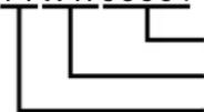
ZP19006F YYW W0 0001
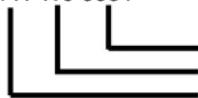
Serial number Week of Production Year of Production
d. If a battery does not want to switch ON and the green LED on the top is not illuminating, irreversible damage has occurred. Under this condition, a battery should not enter into service and should be disposed of according to local authority guidelines.
2. During Use:
a. Batteries must be recharged after every use regardless of machine run time.
b. If the machine is to be left dormant for any length of time complete the following:
i. Fully charge the batteries.
ii. Do not leave batteries dormant for more than 6 months.
Daily
Keep the machine clean.
Ensure brushes/ pads/ squeegee/ fi Iters are in good condition.
Check for any worn or damaged parts and replace immediately.
Drain and rinse dirty water tank after every use.
Store machine with brush deck secured in the elevated position.
Weekly – as daily and –
Check brush or pad and skirt and rinse.
Check floor tool blades for wear and wipe clean.
Clean separator assembly including fi Iter and check condition of seal.
Flush out system with clean water and clean fi Iters.
Batteries
Always re-charge the batteries after use.
Charge for a minimum of 4 hours. Leave the battery on charge overnight, at least once per month.
After it has been fully charged, this will prolong battery life.
| Make | Voltage | Capacity/Energy | Weight | Size |
| NX1K Battery | 25.6 V | 50Ah / 1280 Wh | 10.8 kg | 315mm (L) x 132mm (W) x 185mm (H) |
Numatic Lithium-ion Rechargeable Battery
25.6V | 50Ah | 1280Wh | LFP26148129


natural_image
Weather protection symbol with no text, numbers, or symbols

natural_image
Prohibition sign with no smoking symbol (no text or numbers present)
natural_image
Black circular icon showing a hand washing a faucet (no text or symbols)
natural_image
Stylized black-and-white graphic of an eye with a pointed hat above it, no text or symbols present.It is important that you observe the following information and warnings!
| Emergency Contact Information | ||
| Address: CBAK BATTERY HEADQUARTERS Shenzhen BAK ENERGY Co. LTD, 2603A BAK Tech Bldg, 9th Keyan Rd, Hi-tech Park, Nanshan Dist, Shenzhen City, China | NUMATIC INTERNATIONAL LTD Millfield Road, Chard, Somerset, TA20 2GB, UK | |
| Tel: Fax | 0086-755-832837100086-755-8328649 | 0044-146-0686000044-146-068458 |
| www.numatic.com | www.numatic.de | www.numatic.ch | www.numatic.frwww.numatic.nl | www.numatic.co.za | www.numatic.pt | www.numatic.eswww.numatic.it | www.numatic.dk | ||
1. DEFECTIVE BATTERIES
EN
- If a customer wishes to return a battery to a supplier after removing from product, then collection of the battery must be arranged by the supplier; however, Faulty batteries must not be returned through the postal system or by courier.
- If on return to a supplier, OR at a customer base, a suspected defective battery shows any signs of impact damage, distortion, blistering, loose parts or leakage then on no account should it be offered for condition checking. It must be considered defective and the procedures described from item 6 below should be followed.
- If, on return to a supplier, OR at a customer base, a suspected defective battery, that shows No signs of impact damage, distortion, blistering, loose parts or leakage, may be offered for condition checking with an appropriate battery condition checking device operated by a competent person.
- If checking shows the battery to be defective then the procedures described from item 6 below should be followed.
- On no account must any further attempt to recharge be made. A defective battery should not be stored inside buildings on any account.
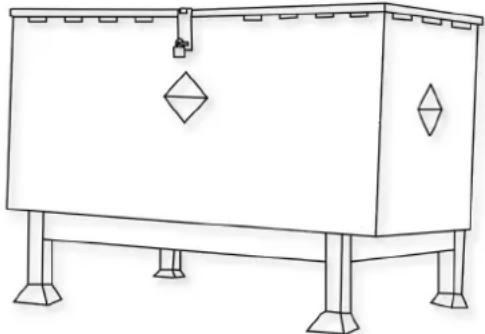
- The defective battery must be switched off, and all electrical terminals sufficiently insulated to remove risk of short circuit. The defective battery can then be stored in a locked battery waste container which should be plastic or plastic lined and placed away from buildings and combustible materials and clearly signed as a defective battery container with appropriate warnings. Defective batteries should be sent for waste disposal / recycling according to your country waste regulations.
natural_image
Line drawing of a rectangular industrial or electrical cabinet with four legs and a central door (no text or symbols)An example of a waste battery storage bin well away from buildings.
2. HANDLING AND STORAGE
EN
DANGER!
Improper handling can lead to an explosion or ignite a fire!
Store batteries out of reach of children.
- Only trained staff can fix the battery in the machine.
- Storage temperature range: -10°C\~40°C.
• Temperatures must not exceed 40^ C.
• Relative humidity range: 20% to 80%. - Optimum preservation of functionality: 15^ 25^ .
WARNING:
- Do not open the battery, disassemble it or allow it to fall from a substantial height
- Protect the battery against short-circuiting – danger of explosion!
- Protect the battery against rain, do not immerse in liquids – danger of short-circuiting.
- Protect the battery against direct sunlight, heat and fire.
- Do not incinerate the battery – danger of explosion!
- Do not use defective or deformed batteries.
- Use only original Numatic specific appliances to charge and discharge batteries.
- Use only an external supply with the following specifications: 100-240V \~ 6.8A.
STORAGE:
• Good batteries should be stored in a protected area away from sources of direct heat and sunlight and should be kept dry.
- The temperature should not exceed 40^ but preferably not be above 25^ to maintain good battery performance.
- Storage area should be of low humidity, non dusty and a non corrosive atmosphere.
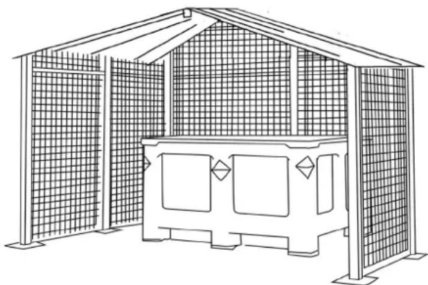
- An example of a well protected area with a cage to protect against accidental impact damage and with the batteries stored in a protective container to protect from heat, impact and accidental spillage of liquids.
- Care when handling / moving with forklift trucks or pallet trucks is needed at all times to avoid any physical damage to the batteries.
- If a good battery at any time is mishandled or subjected to any conditions that may damage it, as described in the battery Instruction manual supplied, it must then be considered as defective and procedures followed from Item 1 of this document overleaf.
natural_image
Line drawing of a traditional-style gage structure with lattice windows and a central platform (no text or symbols)3. HAZARDS IDENTIFICATION
- Electrolyte may escape from damaged batteries. Avoid contact.
- Contact can cause skin irritation, burns and chemical burns.
- If liquid comes into contact with eyes, seek medical attention.
- Avoid inhaling any vapours formed or released from the battery – Contains caustic alkaline electrolytes.
- Warning - Risk of fire - This battery contains No user serviceable parts.
4. FIRST AID MEASURES
In the event of contact with released electrolyte or electrolyte vapours:
• Eye contact – flush eyes for at least 15 minutes with plenty of clean water without rubbing and seek medical attention.
• Skin contact – wash affected areas of skin with plenty of water and soap; if irritation persists, seek medical attention.
- Inhalation – provide fresh air or administer oxygen immediately and seek medical attention.
- Ingestion – if electrolyte has been ingested, seek medical attention immediately.
Information for physicians:
- Contains caustic alkaline electrolytes in cells with Lithium Iron Phosphate – NO LITHIUM METAL OR LITHIUM ALLOYS.
5. FIRE FIGHTING MEASURES
- In case of fire – Keep clear of vapours and gases generated, take wind direction into consideration. If possible without danger, remove batteries from the vicinity of the fire. In principle, cooling or extinguishing with water is possible, but should only be done by trained personnel with sufficiently large quantities of water.
- If the hazard situation is unclear, extinguish only with ABC powder extinguishers (Class D extinguishers for fires involving metals are especially suitable).
• Fire fighters should only approach the fire wearing protective clothing and self-contained breathing apparatus. - Once the fire has been extinguished, as a rule, the area should be monitored (fire watch) and cleaned up by trained and appropriately equipped personnel; fire residue should be contained and disposed of properly.
6. EXPOSURE CONTROLS, PERSONAL PROTECTION
Respiratory Protection:
• In case of battery venting, providing as much ventilation as possible. Avoid confined areas with venting batteries.
- Respiratory Protection is not necessary under conditions of normal use.
Ventilation:
- Not necessary under conditions of normal use.
Protective Gloves:
- Not necessary under conditions of normal use.
Other Protective Clothing or Equipment:
- Not necessary under conditions of normal use.
- Personal Protection is recommended for venting batteries: Respiratory Protection, Protective Gloves, Protective Clothing and safety glass with side shields.
7. ACCIDENTAL RELEASE
Disposal – Wear protective clothing and equipment, wipe up with absorbent textile and dispose of as hazardous waste at collection points for hazardous waste according to national regulations.
8. DO
- Use NUMATIC batteries only with NUMATIC appliances and charge them only using NUMATIC chargers.
- Charge battery before use.
- Store the battery out of the reach of children.
- Protect from rain – do not immerse in fluids.
- Protect from direct sunlight, heat, and open flames.
- Keep a battery that is not in use away from metal objects, (e.g. nails, coins, jewellery).
- Follow the disposal advice of the manufacturer and any internal waste management guidance.
- Use and store the battery with-in temperature range (as shown in Temperature Range Table).
• Always switch off the battery using the button by holding it for 6 seconds, before disconnection and handling. - To activate / turn ON the battery please hold the top button for 6 seconds or alternatively charge the battery using original Numatic specific chargers.
- Be aware of the risk of terminals of the battery-operated appliance or battery being short circuited by metal objects.
Warning: The battery must only be charged by the Numatic Charger supplied with the product and under NO circumstances should an alternative non Numatic charger be used as there is a risk of severe damage and fire could result.
Note* "If batteries are subjected to temperatures beyond normal operating limits automatic shutdown will occur. Under these conditions allow the batteries to acclimatise at room temperature (18°C – 22°C) for several hours to allow the battery to wake up".
| Temperature Range Table | |
| CHARGING 5°C~35°C | |
| DISCHARGING -10°C~35°C | |
| STORAGE OPTIMUM 15°C~25°C | |
| STORAGE LIMIT -10°C~40°C |
9. DO NOT
EN
- Throw battery into fire – risk of explosion!
- Charge or use a defective, damaged or deformed battery.
- Open, damage or drop the battery.
- Expose the battery to microwaves or high pressure.
- Bridge (short circuit) the battery terminals with metallic objects since this may damage the battery.
- Use metal containers for transporting batteries.
- Expose the batteries to high temperatures including direct sunlight.
- Crush, break open or physically abuse the batteries or the equipment that contains them.
10. DISTRIBUTOR TAKE-BACK / DISPOSAL
EN
natural_image
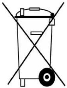
Simple line drawing of a trash bin with diagonal lines crossing it, no text or symbols present.- On the basis of the Battery Directive, the manufacturers take responsibility for financing collection, treatment and recycling of batteries used in devices. To this end, batteries must be handed over for disposal to the collection systems established for this under national law. Disposal of batteries together with household waste is prohibited; batteries must be collected separately according to type.
- Return the battery free of charge to your NUMATIC servicing dealer for disposal or hand it over to an appropriate public collection point.
11. CHARGING BATTERIES
EN
- The charger is intended for use only in the machine where it has been installed. The charger is intended for use with the detachable power cord supplied, the power unit is capable of operating at different voltages without user adjustment. If the charger is damaged or does not charge anymore, please return to service centre.
CAUTION!
- Check the mains cord regularly for any sign of damage.
- Do not use damaged devices.
- If the mains cord of the charger is damaged, it must be replaced by an original NUMATIC mains cord available from the manufacturer or service agent.
12. WARRANTY
EN
Lithium-Ion Battery Warranty
Warranty: Commercial Use
a. Batteries are warranted for (3 Years) as standard. *Note: Numatic dealerships outside of the UK may provide longer warranty periods.
Please confirm with your Numatic dealership on purchase of your product.
b. To claim warranty the following details must be supplied
i. Serial number of the machine
ii. Battery date code
iii. Date purchased
iv. Proof of Purchase
v. Maintenance history and charging regime
Failure to use the correct Numatic charger will void your warranty.
![Numatic® INTERNATIONAL LTD Card Somerset TA20 2GB, United Kingdom 851P Rechargeable Li-Ion Battery Pack HpP27/149/130E631P/0-20-60-99 Voltage 25.6V Capacity 50A) Energy 1280Wh [LFP29148129] P/N 911048 CAUTION: Risk of fire and burns. Do not open, exhaust, heat above +90°C, or increase. Follow manufacturer instruction, need instructions before use. Charge only with Numatic specific charges. Max charge current 25A. Max charge voltage 28.8V. WARNING: To reduce the risk of injury, user read read instruction mead. May cause heat, exploration and fire. ATTENTION: Risques de l'ordado et de brasilones, ne pas pourts, bresseur, chauffer à plus de +80 °C ou incinerer. Suivze les immunitants du fabricant, etc les instructions avant utilisation. Charge uniquement avec le charger spécifique Numatic. Clustant de charge max. 25A, terrain de charge max. 28. IN. ASSETSMENT - Pour provenir les blessures, fûlûteur tout le manuel d'utilisation. Pour sauver de la chaleur, de l'espression et un brocade. UK CA MADE IN CHINA Manufacturer: Shenzhen Ace Battery Co.,Ltd.](/content/2026/04/725098/images/fbe556a2dd64481c2575bacd8e15662c01a4a532c41ae29f451e44afd7ee4a38.jpg)
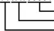
ZP19006-01FYYWW00001
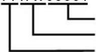
Serial number
Week of production
Year of production
1. SCHADHAFTE BATTERIEN
natural_image
Line drawing of a simple rectangular industrial machine with four legs and a central door (no text or symbols)Beispiel für einen
natural_image
Line drawing of a simple outdoor structure with lattice windows and a central rectangular frame (no text or symbols)3. MÖGLICHE GEFAHREN
natural_image
Simple line drawing of a trash bin with diagonal lines crossing it, no text or symbols present.natural_image
Line drawing of a rectangular industrial or storage unit with four legs and two diamond-shaped cutouts (no text or symbols)natural_image
Line drawing of a simple outdoor structure with lattice windows and a central rectangular frame (no text or symbols)3. IDENTIFICATION DES DANGERS
natural_image
Simple line drawing of a trash bin with diagonal lines crossing it, no text or symbols present.natural_image
Line drawing of a rectangular industrial or electrical cabinet with four legs and a central door (no text or symbols)natural_image
Line drawing of a traditional-style building with lattice windows and a central structure (no text or symbols)3. IDENTIFICATIE VAN RISICO'S
| TEMPERATUURTABEL |
| OPLADEN 5°C tot 35°C |
| ONTLADEN -10°C tot 35°C |
| OPTIMUM VOOR OPSLAG 15°C tot 25°C |
| MAXIMA BIJ OPSLAG -10°C tot 40°C |
natural_image
Simple line drawing of a trash bin with diagonal lines crossing it, no text or symbols present.natural_image
Line drawing of a rectangular industrial or electrical cabinet with four legs and a central door (no text or symbols)natural_image
Line drawing of a simple outdoor structure with lattice windows and a central rectangular frame (no text or symbols)natural_image
Simple line drawing of a trash bin with no text or symbolsNumatic INTERNATIONAL LTD
Chard Somerset TA20 2GB, United Kingdom
8S1P Rechargeable Li-ion Battery Pack IfpP27/149/130(8S1P)H/-20+60/95
Voltage 25.6V | Capacity 50Ah | Energy 1280Wh | LFP26148128 | P/N 61164a
CADITION: Risk of fire and burns. Do not open, clean, heat above +60°C or incinerate. Follow manufacturer instruction, read instructions before use
Charge only with Numatic specific charger, Max charge current 25A, Max
charge voltage 28.8V. WARNING-To reduce the risk of injury, user must read instruction manual. May cause heat, explosion and fire.
MADE IN CHINA
Manufacturer: Shenzhen Ace Battery Co., Ltd.
ZP19006-01FYYWW00001

natural_image
Line drawing of a simple electrical cabinet with four legs and a central door (no text or symbols)natural_image
Line drawing of a traditional-style gablehouse with lattice windows and a central platform (no text or symbols)natural_image
Simple line drawing of a trash bin with no text or symbolsChard Somerset TA20 2GB, United Kingdom
8S1P Rechargeable Li-ion Battery Pack. IFpP27/148/130(8S1P)H/-20+60/95
Voltage 25.8V | Capacity 50Ah | Energy 1280Wh | LFP26148129 | P/N 011948
CAUTION: Risk of fire and burns. Do not open, crush, heat above +60°C
or immenate, Follow manufacturer instruction, read instructions before use.
Charge only with Nominal specific charger, Max charge current 25A. Max charge voltage 28.8V, waensing. To reduce the risk of injury, user must read instruction
change mortgage bill. Simulated 15 October 2014 manual. May cause heat, explosion and fire.
Manufacturer: Shenzhen Ace Battery Co., Ltd.
ZP19006-01FYYWW00001
Numero di serie
natural_image
Line drawing of a simple electrical cabinet with four legs and a central door (no text or symbols)natural_image
Line drawing of a simple outdoor structure with lattice windows and a central rectangular platform (no text or symbols)| TABLA DE INTERVALOS DE TEMPERATURA |
| CARGANDO 5°C~35°C |
| DESCARGANDO -10°C~35°C |
| ALMACENAMIENTO ÓPTIMO 15°C~25°C |
| LÍMITE DE ALMACENAMIENTO -10°C~40°C |
natural_image
Simple line drawing of a trash bin with diagonal lines crossing it, no text or symbols present.Chard Somerset TA20 2GB, United Kingdom
8B1P Rechargeable Li-ion Battery Pack IFpP27/149/130(8S1P)H/-20+60/95
Voltage 25.6V | Capacity 50Ah | Energy 1280Wh | LFP26148129 | P/N 911948
CAUTION: Risk of fire and burns. Do not open, crush, heat above +60°C
or increments. Follow manufacturer instruction, need instructions before use Charge only with Numatic specific charger. Max charge current 25A. May
charge voltage 28.8V. WARNING-To reduce the risk of injury, user must read Instruction
manual. May cause heat, explosion and fire.
natural_image
Line drawing of a rectangular industrial or electrical cabinet with four legs and a central door (no text or symbols)natural_image
Line drawing of a simple outdoor structure with lattice windows and a central rectangular base (no text or symbols)3. IDENTYFIKACJA ZAGROŻEŃ
PL
| TABELA ZAKRESU TEMPERATUR | |
| ŁADOWANIE 5°C~35°C | |
| ROZŁADOWYWANIE -10°C~35°C | |
| OPTYMALNA TEMEPRATURA PRZECHOWYWANIA 15°C~25°C | |
| GRANICZNA TEMPERATURA PRZECHOWYWANIA -10°C~40°C | |
natural_image
Simple line drawing of a trash bin with diagonal lines crossing it, no text or symbols present.natural_image
Line drawing of a rectangular industrial or electrical cabinet with four legs and a central door (no text or symbols)natural_image
Line drawing of a traditional-style building with lattice windows and a central structure (no text or symbols)3. RISKBEDÖMNING
SV
9. GÖR INTE DETTA
SV
natural_image
Simple line drawing of a trash bin with diagonal lines crossing it, no text or symbols present.natural_image
Line drawing of a rectangular industrial or electrical cabinet with four legs and a central diamond-shaped opening (no text or symbols)natural_image
Line drawing of a traditional-style building with lattice windows and a central structure (no text or symbols)4. ENSIAPUTOIMENPITEET
FI
9. VÄÄRIN
FI
natural_image
Simple line drawing of a trash bin with diagonal lines crossing it, no text or symbols present.natural_image
Line drawing of a simple rectangular industrial machine with four legs and a central door (no text or symbols)natural_image
Line drawing of a traditional-style building with lattice windows and a central structure (no text or symbols)| TEMPERATUROMRÅDETABEL | |
| OPLADNING 5°C~35°C | |
| AFLADNING -10°C~35°C | |
| OPTIMAL OPBEVARING 15°C~25°C | |
| OPBEVARINGSGRÅENSE -10°C~40°C | |
natural_image
Simple line drawing of a trash bin with no text or symbolsChard Somerset TA20 2GB, United Kingdom
881P Rechargeable Li-ion Battery Pack. IfpF23/540/T30(RS1P)0/-20-60/95
Voltage 25.6V | Capacity 50Ah | Energy 1280Wh | LFP26148139 | P/N 911946
CAUTION: Risk of fires and burns. Do not open, crush, heat above +60°C or inzwere. Follow manufacturer instruction, next instructions before use
Charge only with Numatic specific charger, Max charge current 25A. Max
charge voltage 28.8V WINKING To reduce the risk of injury, laser must read instruction output. My group best, projector and fire
Hindi: My case was, explosion and fire. ATTENTION: Even as a crowd of the bill.
MADE IN CHINA
Manufacturer: Shenzhen Ace Battery Co., Ltd.
ZP19006-01FYYWW00001
Serienummer
Produktionsuge
Produktionsår
| PROBLEM CAUSE SOLUTION | ||
| Machine will not operate Low battery charge | Machine is connected and chargingWaste tank full switch stuck or cloggedKey is off or missingHandle safety fuse blown | Charge batteries (page 76-92)Take off charge (page 76-81)Inspect & clean switch inside tank (page 58-69)Insert key & turn to operating positionReplace fuse (or contact service engineer) |
| Vacuum will not operate Missing or blown fuse | Waste tank full switch stuck or cloggedVacuum switch not engagedWaste water tank full | Fit or replace fuse (page 16-21)Inspect & clean switch inside tank (page 58-69)Press switchEmpty waste water tank (page 40-45) |
| Poor water pick-up Waste water tank full | Clogged / blocked vacuum hoseLoose hose connectionsDebris basket filter clogged / blockedSeparator filter clogged / blockedPoor separator sealDamaged separator sealDamaged / split vacuum hoseDamaged floor tool bladesLow battery chargeFloor tool incorrectly adjusted | Empty waste water tank (page 40-45)Remove and clean (page 58-69)Push tight connections (page 22-27)Remove and clean (page 58-69)Remove and clean (Page 58-69)Clean and refit (page 58-69)Renew (contact service dept)Renew (contact service dept)Renew (contact service dept)Re-charge batteries (page 76-92)Adjust floor tool |
| No brush / scrub function No brushes fitted | Brush deck raisedMissing or blown fuses | Check and fit (page 28-33)Lower brush deck (page 28-33)Fit or replace fuse (page 16-21) |
| Little or no water flow Clean water tank empty | Clean water tank filter blocked / cloggedWater flow not onBrush deck raised | Fill clean water tank (page 34-39)Remove and clean (page 58-69)Switch on water flow (Page 52-57)Lower brush deck (page 28-33) |
| Machine just ‘stops’ during operating | Brush motor fuse blown due to high load | Replace fuse & reduce load (page 16-21) |
Warning Do not fit a replacement fuse link having a higher rating than the value stated on the fuse label.
DE
Reservedele
| UKCA Declaration of Conformity | ||
| Manufacturer: | Numatic International LimitedChard Somerset TA20 2GBwww.numatic.co.ukNumatic | |
| Product: | CRG, CRL | |
| Description: | Floor Treatment – Ride On – Commercial | |
| We, Numatic hereby declare under our sole responsibility, that the above-mentioned product(s) is/are in conformity with the following directives and standards. | ||
| S.I. 2008: 1597 | Supply of Machinery Regulations | EN60335-1:2012 + AC:2014 + A11:2014 + A13:2017 + A15:2021EN60335-2-72:2012EN62233:2008 |
| S.I. 2016: 1091 | EMC Regulations | EN55014-1:2017 + A11:2020EN55014-2:1997 + A1:2001 + A2:2008EN61000-3-2:2014EN61000-3-3:2013 |
| S.I. 2012: 3032 | RoHS Regulations | |
| Authorised Signatory: Mr. Matthew Coles | Position: Head of TechnologyNumatic International Limited, Chard,Somerset, TA20 2GB, UK | |
| Signed: Date: 1stFebruary 2024 | ||
For declaration of conformity for model CRL8072.TM see supplement sheet part no 920007
Notes
| This Machine Has Been Packed With The Following | |
| Brush / Pad | □ |
| Floor Tool | □ |
| Charging Lead | □ |
| Battery | □ |
| Fuse Pack | □ |
| Signed | |
Distributed by:
Numatic
numatic.com
Numatic International Limited (Head Office)
Chard, Somerset TA20 2GB, UNITED KINGDOM
Tel: 01460 68600 numatic.com
Numatic International GmbH
Fränkische Straße 15-19, 30455 Hannover, DEUTSCHLAND
Tel: +49 (0) 511 984 2160 numatic.de
Numatic International Denmark
Fränkische Straße 15-19, 30455 Hannover, DEUTSCHLAND
Tel: +45 (0) 316 40808 numatic-online.dk
Numatic International S.A.S
Numatic International BV
Numatic International (PTY) Ltd.
Cnr. 16th & Pharmaceutical Road, Randjes Park, Midrand 1685, SOUTH AFRICA
Tel: +27 (0) 861 686 284 numatic.co.za
Numatic International ULDA
Numatic International Spain, S.L.U.
Av. Baix Llobregat, 5-7, Ofi cina bajos 1 (Parc Negocis Mas Blau II)
08820 El Prat de Llobregat (Barcelona), SPAIN
Tel: +34 93 647 22 22 numatic.es
Numatic International Italy S.R.L
Via Luigi Galvani, 2, Z.I. Talponedo, 33080 Porcia (PN), ITALY
Tel: +39 (0) 434 046 211 numatic.it
- EN, DE, FR, NLEN, DNER NL Numatic RT, IT, FO, PL, RT, IT, FORD
- Machine Operation
- DE
- FR
- NL
- PT
- IT
- SV
- FI
- DA
- PLEASE READ, BEFORE COMMENCING OPERATION
- EN
- ENSURE THAT NO METAL OBJECTS COME INTO CONTACT WITH BATTERY TERMINALS WHILE THE BATTERIES ARE EXPOSED.
- Fitting the Hose Guide
- Fitting the Floor Tool
- Break-away Floor Tool
- Floor Tool Transit Bracket
- Filling the Clean Water Tank
- Fill Level Indicator
- EN Machine Operation
- IMPORTANT
- Setting the Cleaning Controls
- Waste Water Tank Full
- Vuilwatertank is vol
- Emergency Stop Button/ Horn
- Maximum Speed Control
- Anti-tip System
- Machine in Use
- Off-aisle Cleaning Kit
- Always ensure that the machine is switched off prior to any maintenance.
- Free Wheel Function
- Always ensure that the machine is switched off prior to maintenance.
- Floor Tool Overview
- Battery Care
- Under normal daily usage:
- der Maschine
- Under abnormal use;
- EN Information for Scrubber Dryer
- READ MANUAL BEFORE USE
- WARNING
- CAUTION
- DO
- DON'T
- Precautions when working with batteries
- During Use:
- Numatic Lithium-ion Rechargeable Battery
- 25.6V | 50Ah | 1280Wh | LFP26148129
- DEFECTIVE BATTERIES
- HANDLING AND STORAGE
- DANGER!
- WARNING:
- STORAGE:
- HAZARDS IDENTIFICATION
- FIRST AID MEASURES
- In the event of contact with released electrolyte or electrolyte vapours:
- Information for physicians:
- FIRE FIGHTING MEASURES
- EXPOSURE CONTROLS, PERSONAL PROTECTION
- Respiratory Protection:
- Ventilation:
- Protective Gloves:
- Other Protective Clothing or Equipment:
- ACCIDENTAL RELEASE
- DO
- DO NOT
- DISTRIBUTOR TAKE-BACK / DISPOSAL
- CHARGING BATTERIES
- CAUTION!
- WARRANTY
- SCHADHAFTE BATTERIEN
- MÖGLICHE GEFAHREN
- IDENTIFICATION DES DANGERS
- IDENTIFICATIE VAN RISICO'S
- IDENTYFIKACJA ZAGROŻEŃ
- PL
- RISKBEDÖMNING
- GÖR INTE DETTA
- ENSIAPUTOIMENPITEET
- VÄÄRIN
- Reservedele
- Notes
- Numatic
Brand : Numatic
Model : CRL8072
Category : Sweeper