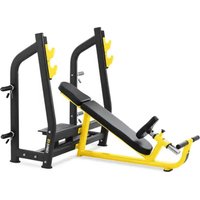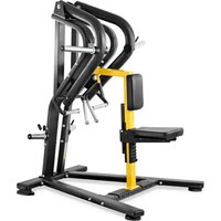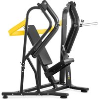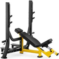
GR-BE 150 - Strength Equipment Gymrex - Free user manual and instructions
Find the device manual for free GR-BE 150 Gymrex in PDF.


User questions about GR-BE 150 Gymrex
0 question about this device. Answer the ones you know or ask your own.
Ask a new question about this device
Download the instructions for your Strength Equipment in PDF format for free! Find your manual GR-BE 150 - Gymrex and take your electronic device back in hand. On this page are published all the documents necessary for the use of your device. GR-BE 150 by Gymrex.
USER MANUAL GR-BE 150 Gymrex
- Schlüssel M6
- Zwei Schlüssel 17/19"
text_image
Technical diagram of a mechanical assembly with numbered components for identificationSchritt II:
1. General Description
The instruction manual is intended to assist in safe and reliable use. The product is designed and manufactured strictly according to technical specifications using the latest technology and components and maintaining the highest quality standards.
PLEASE CAREFULLY READ AND UNDERSTAND THIS INSTRUCTION MANUAL BEFORE OPERATION,
To ensure long and reliable operation of the unit, make sure to operate and maintain it properly in accordance with the guidelines in this instruction manual. The technical data and specifications contained in this instruction manual are up to date. The manufacturer reserves the right to make changes in order to improve the quality. Taking the technical progress and the possibility of reducing noise into account, the unit is designed and built in such a way so that risks resulting from noise emissions are reduced to the lowest possible level.
Explanation of symbols
 | Please read the instructions before use. |
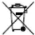 | Recyclable product. |
 | CAUTION! or WARNING! or REMINDER! describing a situation.(general warning sign). |

For indoor use only.

The original instruction manual is in the German language version. Other language versions are translations from German.
2. Safety of use
CAUTION! Read all safety warnings and all instructions. Failure to follow warnings and instructions could result in serious injury or even death.
The term "unit" or "product" in the warnings and in the description of the instructions refers to the BACK EXTENSION BENCH.
2.1. Safety in the workplace
a) Keep the work area tidy and well lit. Disorder or poor lighting can lead to accidents. Be foresighted, watch what you are doing and use common sense when using the unit.
b) If you have any doubts as to whether the product is working properly or if it is damaged, contact the manufacturer's service department.
c) Only the manufacturer's service department may repair the product. Do not carry out repairs yourself!
d) Keep these instructions for use for future reference. If the unit is to be passed on to a third party, the operating instructions must also be handed over together with the unit.
e) Keep the packaging and small assembly parts out of the reach of children.
f) Keep the unit away from children and animals.
2.2. Safe use of the unit
a) Keep unused equipment out of the reach of children and out of the reach of anyone unfamiliar with the unit or this instruction manual. These units is dangerous in the hands of inexperienced users.
b) Keep the unit in good working condition. Check before each use for general damage or damage to moving parts (cracks in parts and components or any
other condition that may affect the safe operation of the unit). If damaged, have the unit repaired before use.
c) When transporting or moving the unit from storage to the place of use, observe the health and safety rules for manual handling applicable in the country where the unit is used.
d) Clean the unit regularly to prevent permanent dirt build-up.
e) The unit is not a toy. Cleaning and maintenance must not be performed by children without adult supervision.
f) Do not start up an empty machine.
g) Do not tamper with the unit to alter its performance or design.
h) Keep the unit away from sources of fire and heat.
i) Do not overload the unit.
j) Exceeding the maximum allowable user weight may result in product damage.
k) Always perform a warm-up before using the unit.
I) If you experience any alarming symptoms while exercising, such as chest pain, dizziness, shortness of breath, etc., stop exercising immediately and consult your physician.
m) Place the unit on a stable, dry, flat surface with a minimum distance of 0.5 m (10 ft) of free space around it.
n) Before exercising, consult your physician to determine your overall general health.
CAUTION! Although the unit has been designed to be safe, with adequate safeguards, and despite the additional safety features provided for the user, there is still a slight risk of accident or injury with the unit. You are advised to use caution and common sense when using this product.
CAUTION! Children under 12 years of age, the elderly, and people with heart problems are not allowed to use the unit.
3. Rules of use
The unit is designed for exercise training of various body parts using appropriate exercises.
The unit is designed for use in professional sports clubs, gyms, hotels, etc.
The user is responsible for any damage resulting from misuse.
3.1. Description
text_image
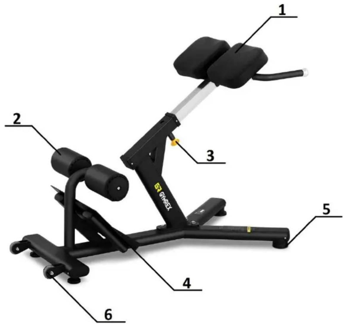
1 2 3 4 5 6 GYMREX1 - Backrest
2 - Leg lock rollers
3 - Backrest height lock
4 - Footrest
5 - Anti-slip base
6 - Roller for easy movement
3.2. Preparation for operation
POSITIONING OF THE UNIT
The unit should be placed on a hard, flat and dry surface. The adjacent surface should be non-slip. Leaving a free space of 2000mmx2000mm around the unit is recommended.
ASSEMBLY OF THE UNIT
In order to properly assemble the unit you should prepare and use the following tools
- M6 wrench
- Two 17/19" wrenches
The assembly of the unit should follow the sequence shown in the illustrations below. Grouping the components together before assembly is recommended.
Components:
| View | Number | Name | Size | Quantity |
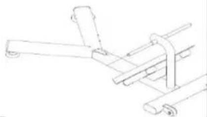 | 1 | Bottom bracket | 1 | |
 | 2 | Connecting the support frame to the bottom frame | 1 | |
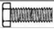 | 3 | Hex head screw with hexagon socket | 3 | |
 | 4 | Washer | 11 × 2 | 3 |
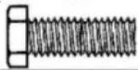 | 5 | Hex head screw with hexagon socket | M8x1.25 | 2 |
 | 6 | Washer | 2 | |
 | 7 | Outer leg lock roller cap | 100 | 2 |
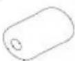 | 8 | Leg lock protection | 125 × 200 | 2 |
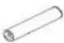 | 9 | Leg lock roller | 40 × 191 | 2 |
 | 10 | Leg lock roller cover | 100 | 2 |
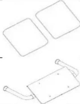 | 11 | Backrest | 2 | |||
| 12 | Backrest frame with handles | 1 | ||||
 | 13 | Hexagon socket screw | M12x1.75 | 2 | ||
 | 14 | Washer | 13.5x2.5 | 4 | ||
 | 15 | Lock nut | M12x1.75 | 2 | ||
 | 16 | Hex head screw with hexagon socket | M8x1.25 | 4 | ||
 | 17 | Washer | 9x1.6 | 4 | ||
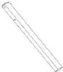 | 18 | Adjustment tube | 50x20x2.5x750 | 1 |
First step "I"
- Connect the unit's bottom rack (1) to the support rack joint (2) using washers (4) and hex socket head screws (3).
- Install the leg lock protection system. To do this, slide the leg lock roller caps (10), leg lock rollers (9), leg lock protection (8), and outer leg lock caps (7) onto the axles of the unit above the footrest.
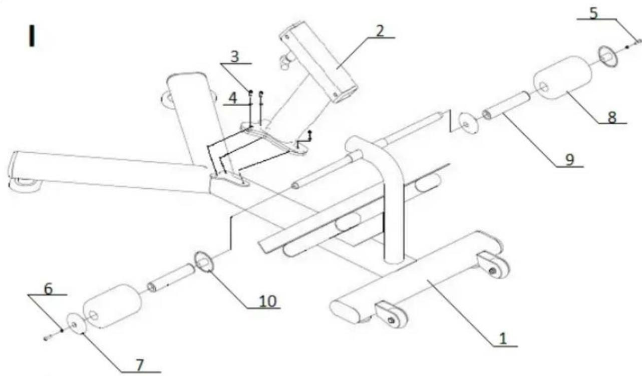
text_image
Technical diagram of a mechanical assembly with numbered components for identificationStep Two "II":
-
Fit the back rest (11) onto the back rest frame (12) and fasten with washers (17) and hexagon socket head cap screws (16).
-
Slide the structure thus prepared into the axis of the support frame connection hole (2).
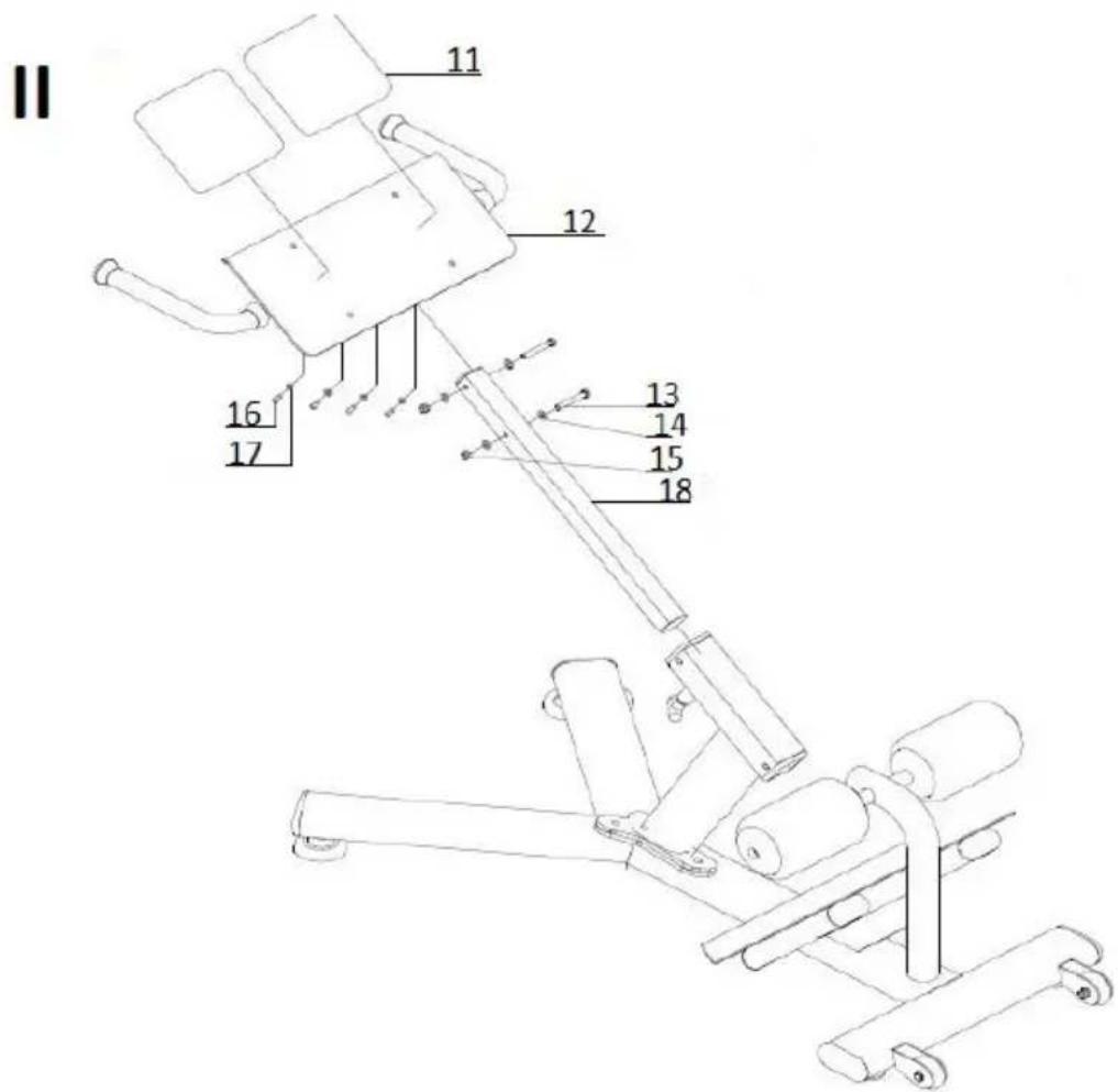
text_image
II 11 12 13 14 15 16 17 18All connections of the unit must be properly fastened and tightened. The unit may be put into operation after these installation steps have been completed.
The height of the unit is adjusted by releasing the backrest height lock and extending or retracting the adjustment tube.
After determining the required height, the adjustment should be blocked by placing the lock in the given hole.

CAUTION! After each adjustment, remember to check whether the rest height locking mechanism is properly seated.
3.3. Cleaning and maintenance
a) Use only non-corrosive cleaning agents for cleaning the surfaces.
b) After each cleaning, all the parts should be dried well before the unit is used again.
c) Store the unit in a dry and cool place protected from moisture and direct sunlight.
d) Do not spray the unit with a stream of water or immerse it in water.
e) Perform regular inspections of the unit checking technical fitness and any damages.
f) Use a soft cloth for cleaning.
g) Do not use sharp and/or metal objects (e.g. a wire brush or metal spatula) for cleaning, as these may damage the surface of the material from which the unit is made.
h) Do not clean the unit with acidic substances, medical products, diluent, fuel, oil or other chemicals as this may cause damage to the unit.
i) Check the attachments and their stability each day before using the unit.
j) Check the stability of the installed backrest and leg lock each day before operating the unit.
k) Once every three months, check that the unit is oiled at the extension points.
DISPOSAL OF USED UNITS.
At the end of its useful life, this product should not be disposed of with normal household waste but should be taken to a collection point for the recycling of electrical and electronic equipment. This is indicated by the symbol on the product, operating instructions or packaging. The materials used in this unit are recyclable according to their marking. You will be making an important contribution to protecting our environment by reusing, recycling or otherwise disposing of used units.
Your local administration will provide you with information about the appropriate disposal point for used units.
Dane techniczne
text_image
Technical diagram of a mechanical assembly with numbered components and labeled partsKrok drugi „II“:
text_image
Technical diagram of a mechanical assembly with numbered components for identificationDruhý krok „II“:
text_image
Technical diagram of a mechanical assembly with numbered components for identificationÉtape 2 :
text_image
Technical diagram of a mechanical assembly with numbered components for identificationSecondo passo "II":
text_image
Technical diagram of a mechanical assembly with numbered components for identificationPaso segundo "II":
text_image
Technical diagram of a mechanical assembly with numbered components and labeled parts„II” második lépés:
APPARATETS PLACERING
text_image
Technical diagram of a mechanical assembly with numbered components for identificationTrin to „II“
OUR CUSTOMERS' SATISFACTION IS OUR MAIN GOAL! PLEASE CONTACT US WITH QUESTIONS AT:
NASZYM GŁÓWNYM CELEM JEST SATYSFAKCJA KLIENTÓW W PRZYPADKU PYTAŃ PROSIMY O KONTAKT Z PRZEDSTAWICIELEM W DANYM KRAJU:
NAŠÍM HLAVNÍM CÍLEM JE SPOKOJENOST NAŠICH ZÁKAZNÍKŮ! V PŘÍPADĚ OTÁZEK NÁS PROSÍM KONTAKTUJTE NA:
NOTRE BUT PREMIER EST VOTRE SATISFACTION! POUR TOUTE QUESTION, CONTACTEZ NOUS SUR: