DCLE14251 - Lighting DEWALT - Free user manual and instructions
Find the device manual for free DCLE14251 DEWALT in PDF.

| Product Type | 5-point and cross line laser level |
| Brand | DeWalt |
| Model | DCLE14251 |
| Laser Class | Class 2 |
| Wavelength | 510 – 530 nm (visible) |
| Laser Power | Lines 2.0 mW, dots 1.0 mW |
| Operating Range | 45 m (without detector), 100 m (with detector) |
| Accuracy | ±3.0 mm per 10 m (level and plumb) |
| Power Source | Integrated Li-ion battery, charging via USB-C |
| Input Power | 5–20 V, ≤3.0 A |
| Weight | 0.97 kg |
| Operating Temperature | 0 °C to 50 °C |
| Storage Temperature | -20 °C to 60 °C |
| Max Humidity | 80% RH at 31 °C, decreasing to 50% at 40 °C |
| Max Altitude | < 2000 m |
| Self-leveling | Yes, range ±4° |
| Tripod Thread | 1/4"-20 and 5/8"-11 |
| Swivel Mount | Magnetic, with multi-surface mounting plate |
| Optional Remote Control | Yes (not included) |
| Maintenance | Clean with a soft, dry cloth; do not use solvents |
| Warranty | Refer to www.DEWALT.eu |
Frequently Asked Questions - DCLE14251 DEWALT
User questions about DCLE14251 DEWALT
0 question about this device. Answer the ones you know or ask your own.
Ask a new question about this device
Download the instructions for your Lighting in PDF format for free! Find your manual DCLE14251 - DEWALT and take your electronic device back in hand. On this page are published all the documents necessary for the use of your device. DCLE14251 by DEWALT.
USER MANUAL DCLE14251 DEWALT
English (original instructions) 35
Fig. D
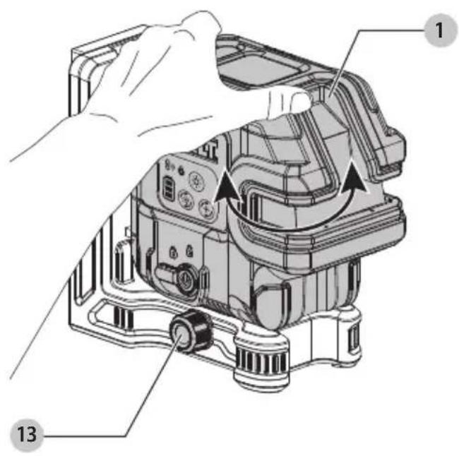
Fig. C

DCLE14221

DCLE14251
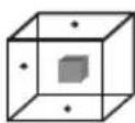
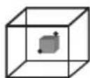
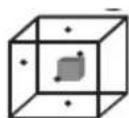
Fig. E
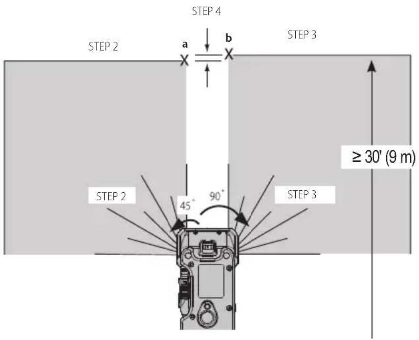
Fig. F
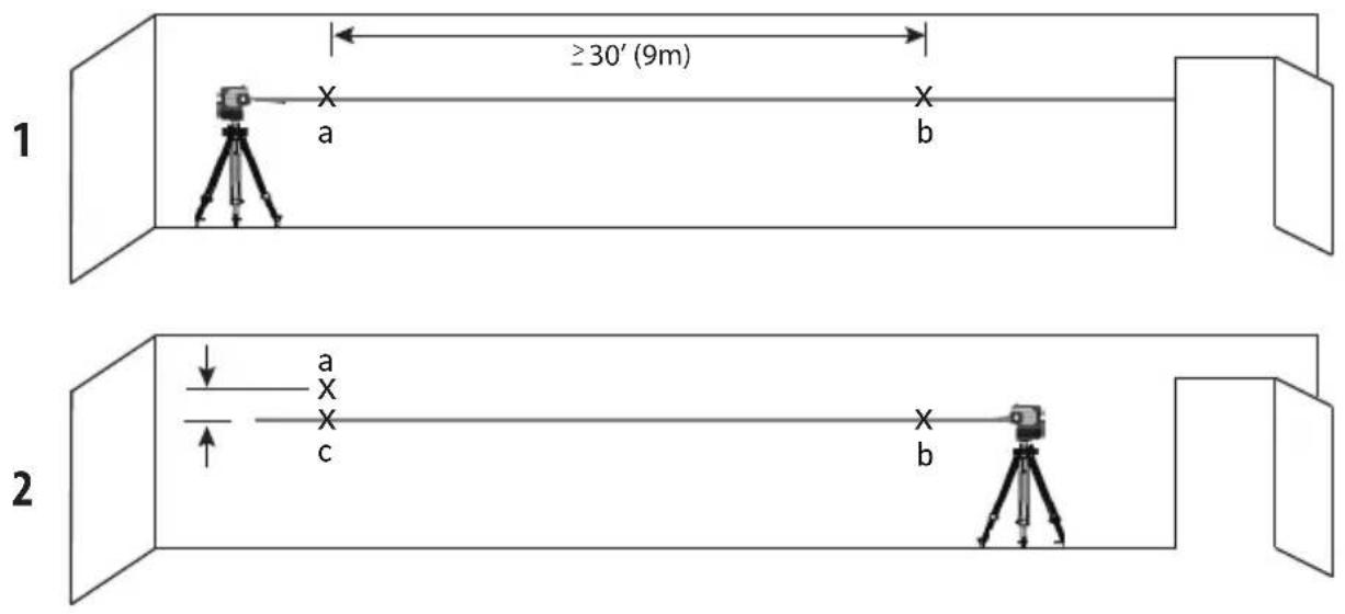
Fig. G
1
Fig. H
2
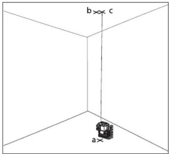
Fig. I 1
2
Fig. J 1 2
3 4
Fig. K
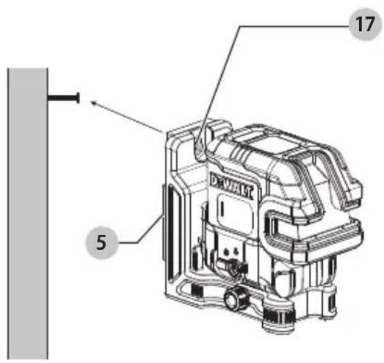
Fig. L
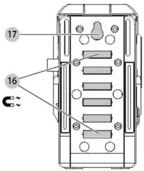
Fig. M
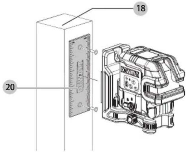
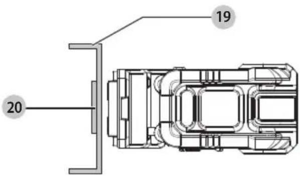
Fig. N Fig. O
natural_image
Line drawing of a tripod-mounted camera setup with no visible text or symbolsFig. P
Dansk
KRYDSLINJE PLUS 2 SPOTS LASER DCLE14221 KRYDSLINJE PLUS 5 SPOTS LASER DCLE14251
Tillykke!
DCLE14221, DCLE14251
Type 1
Indgangsstrøm 5–20V, <= 3,0 A
Tom Burdsall
YP for teknik - HTAS Stanley Black & Decker 701 East Joppa Road, TW120 Towson, MD 21286, USA safe, 13.08.2024
Guilhaume Bonafe EU-repræsentant Stanley Black & Decker 6-8 Rue Gustave Eiffel 91423 Morangis, Frankrig
CROSSLINE PLUS 2-PUNKT-LASER DCLE14221 CROSSLINE PLUS 5-PUNKT-LASER DCLE14251
DCLE14221, DCLE14251
Tom Burdsall
VP of Engineering - HTAS
Stanley Black & Decker
701 East Joppa Road, TW120
Towson, MD 21286, USA
13.08.2024
Guilhaume Bonafé
EU-Vertreter
Stanley Black & Decker
6-8 Rue Gustave Eiffel
91423 Morangis
Frankreich
CROSSLINE PLUS 2 SPOTS LASER DCLE14221 CROSSLINE PLUS 5 SPOTS LASER DCLE14251
Congratulations!
You have chosen a DEWALT laser level. Years of experience, thorough product development and innovation make DEWALT one of the most reliable partners for professional laser level users.
| DCLE14221, DCLE14251 | |
| Type 1 | |
| Light Source Laser diodes | |
| Laser Wavelength | 510 – 530 nm visible |
| Laser Power 2.0 mW lines (each beam) 1.0 mW points (each point) CLASS 2 LASER PRODUCT | |
| Working Range 45 m | |
| 100 m with detector (sold separately) | |
| Accuracy (Plumb) ±3.0 mm per 10 m | |
| Accuracy (Level) ±3.0 mm per 10 m | |
| Battery Low 3 LEDs Flashing on Battery meter | |
| Flashing Laser Beams Tilt range exceeded/unit is not level | |
| Power Source Integral Li-Ion Battery | |
| Input power 5–20V, <= 3.0 A | |
| Operating Temperature | 0 °C to 50 °C |
| Storage Temperature | -20 °C to 60 °C |
| Humidity Maximum relative humidity 80% for temperatures up to 31 °C, decreasing linearly to 50% relative humidity at 40 °C | |
| Altitude < 2000 m | |
| Weight | 0.97 kg |

WARNING: To reduce the risk of injury, read the instruction manual.
Definitions: Safety Guidelines
The definitions below describe the level of severity for each signal word. Please read the manual and pay attention to these symbols.
DANGER: Indicates an imminently hazardous situation which, if not avoided, will result in death or serious injury. WARNING: Indicates a potentially hazardous situation which, if not avoided, could result in death or serious injury.
CAUTION: Indicates a potentially hazardous situation which, if not avoided, may result in minor or moderate injury.
NOTICE: Indicates a practice not related to personal injury which, if not avoided, may result in property damage.
Defutes risk of electric shock.
Deicates risk of fire.
Safety Instructions for Lasers
WARNING! Read and understand all instructions. Follows to follow all instructions listed below may result in electric shock, fire and/or serious personal injury.
SAVE THESE INSTRUCTIONS
- Do not operate the laser in explosive atmospheres, such as in the presence of flammable liquids, gases
ENGLISH
or dust. Power tools create sparks which may ignite the dust or fumes.
- Use the laser only with the specifically designated batteries. Use of any other batteries may create a risk of fire.
- Store idle laser out of reach of children and other untrained persons. Lasers are dangerous in the hands of untrained users.
- Use only accessories that are recommended by the manufacturer for your model. Accessories that may be suitable for one laser, may create a risk of injury when used on another laser.
- Tool service MUST be performed only by qualified repair personnel. Repairs, service or maintenance performed by unqualified personnel may result in injury. For the location of your nearest authorized DEWALT repair agent, refer to the list of authorised DEWALT repair agents on back of this manual or visit www.2helpU.com on the Internet.
- Do not use optical tools such as a telescope or transit to view the laser beam. Serious eye injury could result.
- Do not place the laser in a position which may cause anyone to intentionally or unintentionally stare into the laser beam. Serious eye injury could result.
- Do not position the laser near a reflective surface which may reflect the laser beam toward anyone's eyes. Serious eye injury could result.
- Turn the laser off when it is not in use. Leaving the laser on increases the risk of staring into the laser beam.
- Do not operate the laser around children or allow children to operate the laser. Serious eye injury may result.
- Do not remove or deface warning labels. If labels are removed user or others may inadvertently expose themselves to radiation.
- Position the laser securely on a level surface. Damage to the laser or serious injury could result if the laser falls.
- Conventional fire extinguishers may not be effective at putting out lithium-ion battery fires. Use a foam extinguisher containing CO2, powder graphite, ABC dry chemical, or sodium carbonate.
WARNING: Use of controls or adjustments or performance of procedures other than those specified herein may result in hazardous radiation exposure.
WARNING! DO NOT DISASSEMBLE THE LASER. There are no user serviceable parts inside. Disassembling the laser will void all warranties on the product. Do not modify the product in any way. Modifying the tool may result in hazardous laser radiation exposure.
WARNING: Fire hazard! Avoid short-circuiting the contacts of a removed battery.
Additional Safety Instructions for Lasers
- Do not replace a laser diode with a different type. If damaged, have the laser repaired by an authorised repair agent.
- Do not use the laser for any purpose other than projecting laser lines.
- An exposure of the eye to the beam of a class 2 laser is considered safe for a maximum of 0.25 seconds. Eyelid reflexes will normally provide adequate protection.
- Never look into the laser beam directly and intentionally.
- Do not use optical tools to view the laser beam.
- Do not set up the tool at a position where the laser beam can cross any person at head height.
- Do not let children come in contact with the laser.
Residual Risks
The following risks are inherent to the use of this device:
• injuries caused by staring into laser beam.
Labels on the tool
The following pictographs are shown on the tool:


Read the instruction manual before use.
Laser warning.

Do not stare into the laser beam.
Important Safety Instructions for All Integral Battery Charging
WARNING: Read all safety warnings, instructions, cautionary markings for the battery, USB cable and product. Failure to follow the warnings and instructions may result in electric shock, fire and/or serious injury.
WARNING: Only charge product using a certified power adapter that is compliant with applicable country regulations and international/regional safety standards. Using adapters that do not meet applicable safety standards could result in injury.
- Use only a power supply and cable recommended by the manufacturer for charging.
- Charge this laser every month if not in constant use, and after each use when used often to ensure battery longevity.
- The provided USB cable is not intended for any uses other than charging DEWALT rechargeable tools with
EnGLIsh
USB-C ports. Charging other types of tools may cause their batteries to overheat and burst, resulting in personal injury, property damage, fire, electric shock or electrocution.
• DO NOT expose USB cable to water, rain or snow.
- Pull by the plugs rather than the cord when disconnecting the USB cable. This will reduce the risk of damage to the plugs and cord.
- Make sure that the cord is located so that it will not be stepped on, tripped over or otherwise subjected to damage or stress.
- DO NOT use a USB cable with a damaged cord or plugs. Have them replaced immediately.
- Foreign materials of a conductive nature, such as, but not limited to, grinding dust, metal chips, steel wool, aluminum foil or any buildup of metallic particles should be kept away from the USB and USB-C plugs and port.
• Always unplug the USB cable from the power supply when there is no tool attached to it.
Personal Safety
- Stay alert, watch what you are doing, and use common sense when operating the laser level. Do not use the laser level when you are tired or under the influence of drugs, alcohol, or medication. A moment of inattention while operating the laser level may result in serious personal injury.
- Use personal protective equipment. Always wear eye protection. Depending on the work conditions, wearing protective equipment such as a dust mask, non-skid safety shoes, hard hat, and hearing protection will reduce personal injury.
Laser Level Use and Care
- Do not use the laser level if the pendulum lock/unlock and power switch do not turn the laser level on or off. Any laser level that cannot be controlled with the switch is dangerous and must be repaired.
ENGLISH
- Follow instructions in the Maintenance section of this manual. Use of unauthorised parts or failure to follow Maintenance instructions may create a risk of electric shock or injury.
Date Code Position (Fig. A)
The production date code 21 consists of a 4-digit year followed by a 2-digit week and is extended by a 2-digit factory code.
Before First-Time Use
- Check for damage to the tool, parts or accessories which may have occurred during transport.
• Take the time to thoroughly read and understand this manual prior to operation.
Description (Fig. A)
WARNING: Never modify the power tool or any part of image or personal injury could result.
1 Laser head
2 Laser window
3 Laser label location
4 USB cover
5 Magnetic pivot bracket
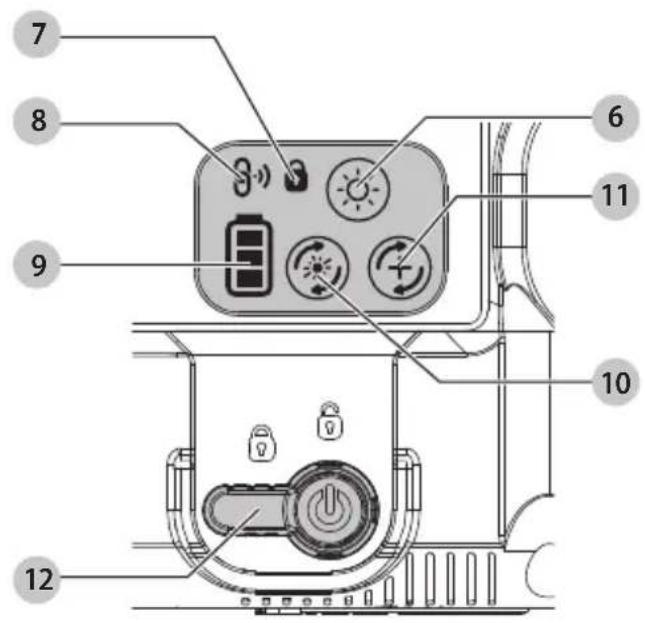
6 Brightness control button
7 Pendulum lock indicator
8 Remote control link indicator
9 Battery meter
10 Laser dots on/off button
11 Laser lines on/off button
12 Pendulum lock/unlock and power switch
13 Fine adjust knob
14 USB cable
Intended Use
The DCLE14221 cross combo 2 spot laser and the DCLE14251 cross combo 5 spot laser are Class 2 laser products. They are self-leveling laser tools that can be used for horizontal (level) and vertical (plumb) alignment projects.
DO NOT use under wet conditions or in presence of flammable liquids or gases.
The crossline laser is a professional tool. DO NOT let children come into contact with the tool. Supervision is required when inexperienced operators use this tool.
- This product is not intended for use by persons (including children) suffering from diminished physical, sensory or mental abilities; lack of experience, knowledge or skills unless they are supervised by a person responsible for their safety. Children should never be left alone with this product.
Charging Procedure (Fig. A, B)
- Pull the USB charging port cover 4 away from the laser level.
- Use a compatible power supply with this unit. For best results, use a USB Power Delivery (PD) capable power supply of 45W or greater.
- Insert the USB cable 14 into the charging port 15.
- Plug the power supply into a wall outlet.
- Charging is complete when all three bars of the battery meter 9 light up on the side of the laser level. The battery can be left charging or the USB cable can be disconnected.
Important Charging Notes
- The laser level may become warm to the touch while charging. This is a normal condition, and does not indicate a problem. To facilitate the cooling of the laser level after use, avoid placing the laser level in a warm environment such as in a metal shed or an uninsulated trailer.
- If the laser level does not charge properly, take the laser level and USB cable to your local service center.
- You may charge a partially used battery whenever you desire with no adverse effect on the laser level
NOTE: The laser level may be used while charging.
Hot and Cold Condition
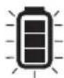
On charging, when the temperature is 52 °C or higher (hot condition) or 0 °C or colder (cold condition), the charging is turned off and following battery state of charge pattern will flash:
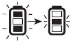
Until the temperature is between 50 °C and 0 °C, the charging will not turn on and the indication shown above will continue.
Viewing the Battery Meter (Fig. A, C)
When the laser level is ON, the state of battery meter 9 on the keypad indicates how much power remains.
- All three LEDs will flash when the battery level is low (< 10%). The laser level may continue to operate for a short time while the battery power continues to drain.
• After the battery is charged, and the laser level is turned ON again, the battery indicator level will indicate full capacity. - If any or all of the LEDs on the battery meter remain ON, this indicates that the laser level is not fully powered OFF. When the laser level is not in use, make sure the pendulum lock/unlock and power switch 12 is placed in the DOWN LOCKED/OFF position.
BATTERY
METER LED
STATE OF CHARGE

Battery is 80%–100% charged

Battery is 50%–80% charged
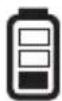
Battery is 10%–50% charged
Battery is < 10% charged
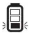
Battery is < 10% charged, unit is charging
OPERATING TIPS
• To extend battery life per charge, turn the laser level off when it is not in use.
- Lowering the brightness of laser level increases battery life.
• To ensure the accuracy of your work, check the laser level calibration often. Refer to Checking Laser Accuracy.
- Before attempting to use the laser level, make sure it is positioned securely, on a smooth, flat stable surface that is level in both directions.
CAUTION: To reduce the risk of serious injury, never stare directly into the laser beam with or without glasses.
• Always mark the center of the beam created by the laser level.
- Extreme temperature changes can cause movement or shifting of building structures, metal tripods, equipment, etc., which can affect accuracy. Check your accuracy often while working.
- If the laser level has been dropped, check to make sure your laser level is still calibrated. Refer to Checking Laser Accuracy.
Turning the Laser On (Fig. C)
Your laser level is equipped with a three-position pendulum lock/unlock and power switch 12.
• Horizontal position: Power off
• Middle position: Power On, Pendulum Locked
• Vertical position: Power On, Pendulum Unlocked
ENGLISH
The laser beams will turn on automatically if the pendulum lock/unlock and power switch is moved from the horizontal position to either the middle position or the vertical position. When the switch is placed in the middle position, the laser unit is in manual leveling mode. The laser will not self level in this mode and is used in situations where a fixed laser line is required. The laser is NOT LEVEL when the pendulum lock indicator is illuminated, and the beams will flash every 10 seconds to further indicate this.
The pendulum lock indicator 7 illuminates when the pendulum is locked and power switch is engaged (middle position).
With the laser level off, place it on a flat surface. This model has a keypad to activate the laser beams with two cycle buttons; one for laser lines 11 and one for laser dots 10. Each laser line is powered on by moving the pendulum lock switch to the UNLOCKED/ON position and pressing the required cycle button on the keypad. The laser lines can be powered one at a time or at the same time. Pressing the cycle buttons again turns the laser lines off. The pendulum locking switch disables the lasers as well as locking the pendulum, and should always be placed in the LOCKED/OFF position when the laser is not in use.
Laser Line Brightness (Fig. A, C)
The brightness of the laser lines can be adjusted by pressing the brightness control 6 button on the keypad which will cycle through high, medium, and low brightness.
Rotating the Laser Head (Fig. D)
The laser head 1 is permanently attached to the laser level base. This laser head can be manually rotated by hand by gripping the laser head and rotating, or by using the fine adjust knob 13 for smaller, more precise movements.
Remote Control Compatible (Fig. A)
Optional Accessory
Only available via service centres
WARNING: Do not operate the laser level via remote control when not in the same room or in presence of the laser level.
An optional remote control allows one person to set up and operate the laser level from a distance.
The remote control link indicator 8 flashes blue to indicate a remote control is ready to pair.
The functions on the remote keypad are identical to the functions on the laser level itself (laser lines on/off button 11, laser dots on/off button 10, brightness control button 6).
Checking Laser Accuracy
The laser levels are calibrated and sealed at the factory. It is recommended that you perform an accuracy check prior to using the laser level for the first time (in case the laser level was exposed to extreme temperatures) and then regularly to ensure the accuracy of your work. When performing any of the accuracy checks listed in this manual, follow these guidelines:
- Use the largest area/distance possible, closest to the operating distance. The greater the area/distance, the easier to measure the accuracy of the laser. Refer to Field Calibration Check.
- Place the laser level on a smooth, flat, stable surface that is level in both directions.
• Mark the center of the laser line.
Field Calibration Check
Checking Accuracy – Horizontal Beam, Scan Direction (Fig. E)
Checking the horizontal scan calibration of the laser level requires two walls at least 9 m (30') apart. It is important to conduct a calibration check using a distance no shorter
ENGLISH
than the distance of the applications for which the tool will be used.
- Attach the laser level to a wall using its pivot bracket. Make sure the laser level is facing straight ahead.
- Turn on the laser level's horizontal beam and pivot the laser level approximately 45^ so that the rightmost end of the laser line is striking the opposing wall at a distance of at least 9 m (30'). Mark the center of the beam (a).
- Pivot the laser level approximately 90^ to bring the leftmost end of the laser line around to the mark made in step 2. Mark the center of the beam (b).
- Measure the vertical distance between the marks.
If the measurement is greater than the values shown below, the laser level must be serviced at an authorised service centre.
| Distance Between Walls Allowable Distance Between a and b | |
| 9.0 m 3.1 mm | |
| 12.0 m 4.2 mm | |
| 15.0 m 5.2 mm | |
Checking Accuracy – Horizontal Beam, Pitch Direction (Fig. F)
Checking the horizontal pitch calibration of the laser level requires a single wall at least 9 m (30') long. It is important to conduct a calibration check using a distance no shorter than the distance of the applications for which the tool will be used.
- Attach the laser level to one end of a wall using its pivot bracket.
- Turn on the laser level's horizontal beam and pivot the laser head toward the opposite end of the wall and approximately parallel to the adjacent wall.
- Mark the center of the beam at two locations (a, b) at least 9 m (30') apart.
-
Reposition the laser level to the opposite end of the wall.
-
Turn on the laser level's horizontal beam and pivot the laser head back toward the first end of the wall and approximately parallel to the adjacent wall.
- Adjust the height of the laser level so that the center of the beam is aligned with the nearest mark (b).
- Mark the center of the beam (c) directly above or below the farthest mark (a).
- Measure the distance between these two marks (a, c). If the measurement is greater than the values shown below, the laser level must be serviced at an authorised service centre.
| Distance Between Walls Allowable Distance Between a and c | |
| 9.0 m 6.2 mm | |
| 12.0 m 8.3 mm | |
| 15.0 m 10.4 mm | |
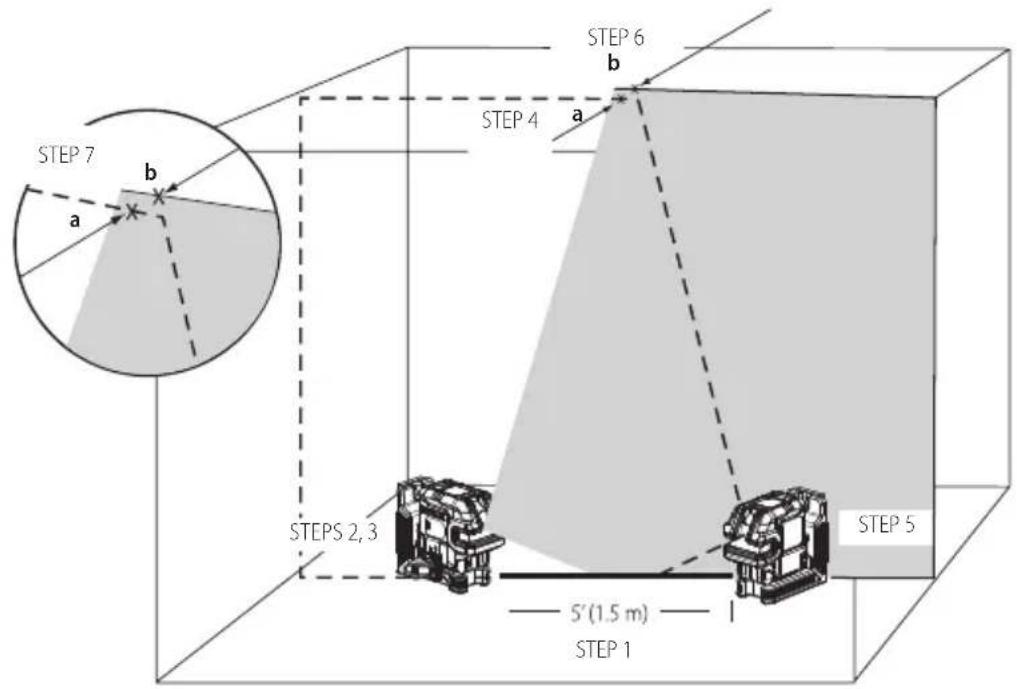
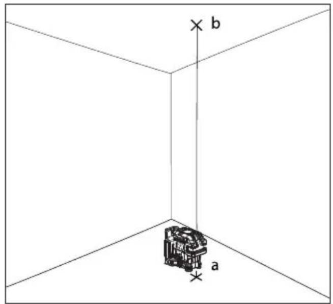
Checking Accuracy – Vertical Beam (Fig. G)
Checking the vertical (plumb) calibration of the laser level can be most accurately done when there is a substantial amount of vertical height available, ideally 6 m (20'), with one person on the floor positioning the laser level and another person near a ceiling to mark the position of the beam. It is important to conduct a calibration check using a distance no shorter than the distance of the applications for which the tool will be used.
- Start by marking a 1.5 m (5') line on the floor.
- Turn on the laser level's vertical beam and position the unit at one end of the line, facing the line.
- Adjust the unit so its beam is aligned and centered on the line on the floor.
- Mark the position of the laser beam on the ceiling (a). Mark the center of the laser beam directly over the midpoint of the line on the floor.
- Reposition the laser level at the other end of the line on the floor. Adjust the unit once again so its beam is aligned and centered on the line on the floor.
ENGLISH
- Mark the position of the laser beam on the ceiling (b), directly beside the first mark (a).
- Measure the distance between these two marks. If the measurement is greater than the values shown below, the laser level must be serviced at an authorised service centre.
| Distance Between Walls Allowable Distance Between a and b | |
| 2.5 m 1.7 mm | |
| 3.0 m 2.1 mm | |
| 4.0 m 2.8 mm | |
| 6.0 m 4.1 mm | |
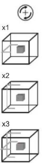
Plumb Dot Accuracy (Fig. A, H)
Checking the plumb calibration of the laser level can be most accurately done when there is a substantial amount of vertical height available, ideally 6 m (20'), with one person the floor positioning the laser level and another person near a ceiling to mark the dot created by the beam on the ceiling
- Turn the laser level ON and press laser dots on/off button 10 once to display dots above and below the laser level.
- Place the laser level so that the down dot is centered over point (a) and mark the down dot. Mark the center of the up dot on the ceiling as point (b) (Fig. A, H1).
- Turn the laser level 180^ , making sure that the down dot is still centered on point (a) on the floor (Fig. A, H2).
- Mark the center of the up dot on the ceiling as point (c) (Fig. A, H2).
- Measure the distance between points (b) and (c). If your measurement is greater than the Allowable Distance Between (b) & (c) for the corresponding Distance Between Ceiling & Floor in the following table, the laser level must be serviced at an authorised service centre.
| Distance Between Ceiling & Floor | Allowable Distance Between b & c |
| 2.5 m 1.7 mm | |
| 3.0 m 2.1 mm | |
| 4.0 m 2.8 mm | |
| 6.0 m 4.1 mm |
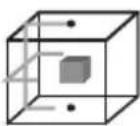
Level Dot Accuracy - Level (Fig. I)
Checking the level calibration of the laser level requires two parallel walls at least 6 m (20') apart.
- Turn the laser level ON and press three times to display dots above, ahead, below, and to the right and left of the laser level.
- Place the laser level 5–8 cm (2"-3") from the first wall. test the front laser dot, make sure the front of the laser level is facing the wall (Fig. I1).
Mark the laser dot position on the first wall as point (a) (Fig. I1).
Turn the laser level 180^ and mark the laser dot position on the second wall as point (b) (Fig. I1).
- Place the laser level 5–8 cm (2"-3") from the second wa To test the front laser dot, make sure the front of the laser level is facing the wall (Fig. I2), and adjust the height of the laser level until the laser dot hits point (b).
- Turn the laser level 180^ and aim the laser dot near dot point (a) on the first wall, and mark point (c) (Fig. I2)
- Measure the vertical distance between points (a) and (c) on the first wall.
- If your measurement is greater than the Allowable Distance Between (a) & (c) for the corresponding Distance Between Walls in the following table, the laser level must be serviced at an authorised service centre.
- Repeat steps 2 through 8 to check the accuracy of the right dot and then the left dot, making sure that the laser dot you are testing is the laser dot facing each wall.
ENGLISH
| Distance Between Walls Allowable Distance Between a & c | |
| 6.0 m 4.1 mm | |
| 10.0 m 6.2 mm | |
| 15.0 m 10.2 mm | |
Level Dot Accuracy - Square (Fig. J)
Checking the level calibration of the laser level requires a room at least 6 m (20') long. All marks can be made on the floor by placing a target in front of the level or square beam and transferring the location to the floor.
NOTE: To ensure accuracy, the distance (D1) from (a) to (b), (b) to (c), (b) to (d), and (b) to (e) should be equal.
- Turn the laser level ON and press once to display dots above, ahead, and below the laser level.
- Mark point (a) on the floor at one end of the room, as shown in Fig. J1.
- Place the laser level so that the down dot is centered over point (a) and make sure the front dot points toward the far end of the room (Fig. J1).
- Using a target to transfer the front level dot location on the wall to the floor, mark point (b) on the floor and then point (c) on the floor (Fig. J1).
- Move the laser level to point (b) and align the front level dot to point (c) again (Fig. J2).
- Using a target to transfer the front level dot location on the wall to the floor, mark the location of two dots as points (d) and (e) on the floor (Fig. J2).
- Turn the laser level 90° so the front level dot aligns to point (e) (Fig. J3).
- Mark the location of the first square beam as point (f) on the floor as close as possible to point (a) (Fig. J3).
-
Measure the distance between points (a) and (f) (Fig. J3). If your measurement is greater than the Allowable Distance Between (a) and (f) for the corresponding Distance (D1) in the following table, the laser level must be serviced at an authorised service centre.
-
Turn the laser level 180^ so the front level dot aligns to point (e) (Fig. J4).
- Mark the location of the second dot as point (g) on the floor as close as possible to point (a) (Fig. J4).
- Measure the distance between points (a) and (g) (Fig. J4).
- If your measurement is greater than the Allowable Distance Between (a) & (g) for the corresponding Distance (D1) in the following table, the laser level must be serviced at an authorised service centre.
| Distance (D1) Allowable Distance Between a & for a & g | |
| 6.0 m 5.3 mm | |
| 9.0 m 7.9 mm | |
| 15.0 m 13.1 mm | |
Using the Laser (Fig. N)
Leveling the Laser
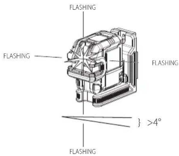
As long as the laser level is properly calibrated, the laser level is self-leveling (in pendulum unlocked mode). Each laser level is calibrated at the factory to find level as long as it is positioned on a flat surface within average ±4^ of level. No manual adjustments are required.
If the laser level has been tilted so much that it cannot self-level ( >4^ ), the laser beam will flash. There are two flashing sequences associated with the out of level condition.
- In pendulum unlocked mode, the laser diode blinks continuously.
- In manual slope mode, the laser diode blinks three times every ten seconds (total cycle), repeating this pattern continuously.
When the beams flash THE LASER LEVEL IS NOT LEVEL (OR PLUMB) AND SHOULD NOT BE USED FOR DETERMINING OR MARKING LEVEL OR PLUMB.
Fine Adjust (Fig. A)
The fine adjustment knob 13 on the side of the laser level is for lining up the vertical beam. Place the laser level on a flat
EnGLIsh
surface and turn the knob to the right (clockwise) to rotate the laser level to the left, or to the left (anticlockwise) to move the beam to the right.
Using the Pivot Bracket (Fig. K, L)
The laser level has a magnetic pivot bracket 5 permanently attached to the unit.
WARNING: Position the laser level and/or wall mount on a stable surface. Serious personal injury or damage to the laser level may result if the laser level falls.
- The bracket has a keyhole slot 17 so it can be hung from a nail or screw on any kind of surface.
- The bracket has magnets 16 which allow the unit to be mounted to most upright surfaces made of steel or iron. Common examples of suitable surfaces include steel framing studs, steel door frames, and structural steel beams.
Multi-Surface Mounting Plate (Fig. L, M)
- To attach the laser level to a wooden stud 18, screw in multi-surface mounting plate 20 first and mount laser level using the laser's magnets 16.
- To attach the laser level to a metal stud 19, sandwich the metal stud between the multi-surface mounting plate 20 and the laser's magnets 16. Placing the multi-surface mounting plate behind the metal stud will significantly increase the magnetic strength and holding capacity of the laser level.
MAINTENANCE
Your laser level has been designed to operate over a long period of time with minimum maintenance. Continuous satisfactory operation depends upon proper tool care and regular cleaning.
WARNING: To reduce the risk of serious personal injury, turn laser level off before making any adjustments or removing/installing attachments or accessories. An accidental start-up can cause injury.
- To maintain the accuracy of your work, check the laser level often to make sure it is properly calibrated. Refer to Field Calibration Check.
- Calibration checks and other maintenance repairs may be performed by DEWALT service centres.
- Do not store your laser level in the case if the laser level is wet. The laser level should be dried first with a soft, dry cloth prior to storage.
Cleaning
WARNING: Never use solvents or other harsh chemicals for cleaning the non-metallic parts of the laser level. These chemicals may weaken the materials used in these parts. Use a cloth dampened only with water and mild soap. Never let any liquid get inside the laser level; never immerse any part of the laser level into a liquid.
Exterior plastic parts may be cleaned with a damp cloth. Although these parts are solvent resistant, NEVER use solvents. Use a soft, dry cloth to remove moisture from the laser level before storage.
TROUBLESHOOTING
The Laser Level Does Not Turn On (Fig. A)
• Fully charge the battery.
- If the laser level is exposed to extremely hot/cold temperatures, the battery meter 9 will flash. Refer to Hot and Cold Condition. If the laser level has been stored in extremely hot temperatures, allow it to cool. The laser level will not be damaged by pressing the on/off button before cooling to its proper operating temperature.
The Laser Beams Flash (Fig. N)
In manual slope mode, flashing will occur 3 times every 10 seconds regardless of tilt, to remind the user they are in manual slope mode.
ENGLISH
In unlocked mode, if the laser unit is tilted more than 4^ , the unit will flash every second, to indicate that while they are in self leveling mode, the unit is too tilted to properly self level. THE FLASHING BEAMS CREATED BY THE LASER LEVEL ARE NOT LEVEL OR PLUMB AND SHOULD NOT BE USED FOR DETERMINING OR MARKING LEVEL OR PLUMB. Try repositioning the laser level on a more level surface. If the laser level battery has a low state of charge, the beams will flash in a distinctive pattern of 3 quick flashes in 1 second, followed by constant light output for 4 seconds. This flashing pattern indicates that the battery should be recharged.
The Laser Beams Will Not Stop Moving
The laser level is a precision instrument. Therefore, if it is not positioned on a stable (and motionless) surface, the laser level will continue to try to find level. If the beam will not stop moving, try placing the laser level on a more stable surface. Also, try to make sure that the surface is relatively flat, so that the laser level is stable.
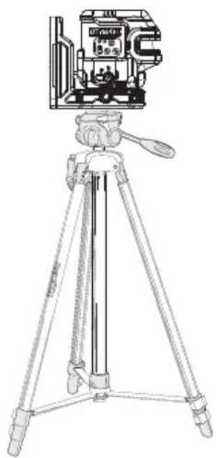
Accessories (Fig. O)
The laser level is equipped with a 1/4"-20 and 5/8"-11 threads on the bottom of the unit to accommodate current or future DEWALT accessories, such as a tripod.
Fig. O shows an example of accessories that are sold separately from these laser levels. Only use DEWALT accessories specified for use with this product. Follow the directions included with the accessory.
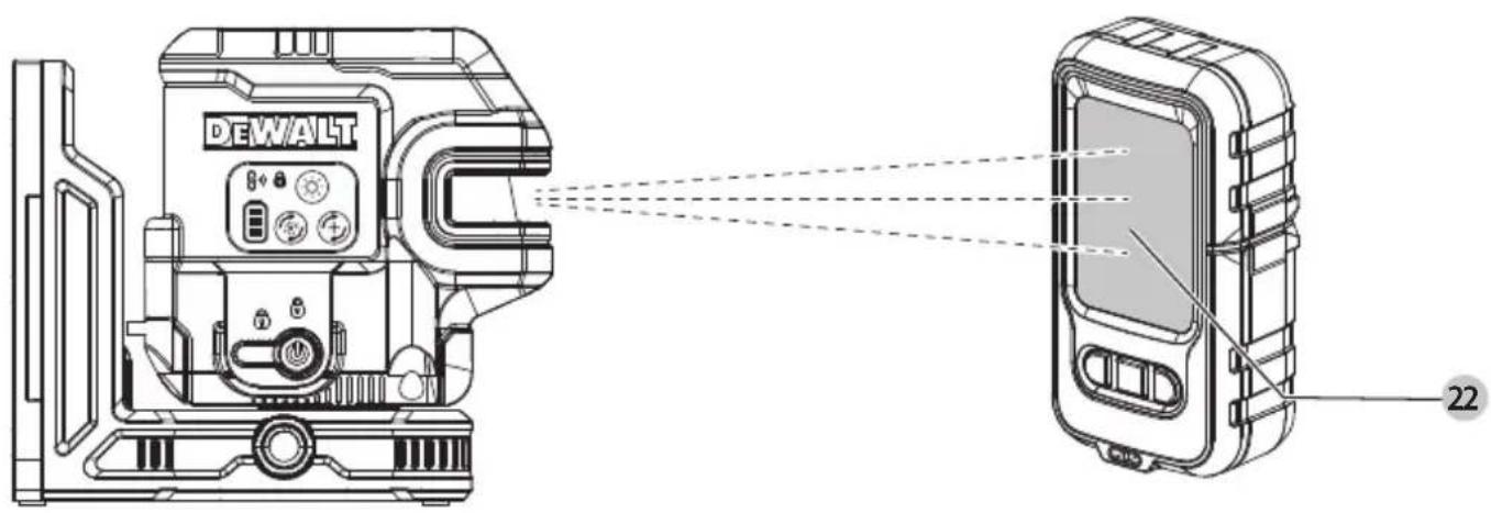
Laser Detector (Fig. P)
The laser detector 22 allows the laser line to be detected at much further distances than the visible range. DE0892G-XJ for the DCLE14201R red laser. DE0892G-XJ for the DCLE14201G green laser.
WARNING: Since accessories, other than those offered by DEWALT, have not been tested with this product, use of such accessories with this laser level could be hazardous. To reduce the risk of injury, only DEWALT
recommended accessories should be used with this product.
If you need any assistance in locating any accessory, please contact your nearest DEWALT dealer, or go to www.DEWALT.eu.
Service and Repairs
NOTE: Disassembling the laser level will void all warranties on the product.
To assure product SAFETY and RELIABILITY, repairs, maintenance and adjustment, such as service to the internal battery should be performed by authorised service centres. Service or maintenance performed by unqualified personnel may result in a risk of injury. To locate your nearest DEWALT service centre, go to www.2helpu.com.
Warranty
Go to www.DEWALT.eu for the latest warranty information.
EU-Declaration of Conformity Radio Equipment Directive

Crossline Plus 2 Spots Laser DCLE14221 Crossline Plus 5 Spots Laser DCLE14251
DEWALT declares that these products described under Technical Data are in compliance with:
2014/53/EU, EN 61326-1:2021, EN 300 328 V2.2.2:2019, EN 62479:2010, EN 61010-1:2010/A1:2019, EN 60825-1:2014/A11:2021, EN 50689:2021.
These products also comply with Directive 2011/65/EU. For more information, please contact DEWALT at the following address or refer to the back of the manual.
EnGLIsh
The undersigned is responsible for compilation of the technical file and makes this declaration on behalf of DEWALT.

Tom Burdsall
VP of Engineering - HTAS
Stanley Black & Decker
701 East Joppa Road, TW120
Towson, MD 21286, USA
13.08.2024
Guilhaume Bonafe
EU Representative
Stanley Black & Decker
6-8 Rue Gustave Eiffel
91423 Morangis, France
DCLE14221, DCLE14251
A11:2021, EN 50689:2021.
Tom Burdsall
701 East Joppa Road, TW120
DCLE14221, DCLE14251
Tom Burdsall
701 East Joppa Road, TW120
Towson, MD 21286, USA
13.08.2024
Guilhaume Bonafe
Représentant Europe
Stanley Black & Decker
6-8 Rue Gustave Eiffel
91423 Morangis, France
LASER A LINEE INCROCIATE CON 2 RAGGI SPOT DCLE14221 LASER A LINEE INCROCIATE CON 5 RAGGI SPOT DCLE14251
Complimenti!
DCLE14221, DCLE14251
Rilevatore laser (Fig. P)
Tom Burdsall
Vicepresidente Engineering - HTAS
Stanley Black & Decker
701 East Joppa Road, TW120
DCLE14221, DCLE14251
VP of Engineering - HTAS
Stanley Black & Decker
701 East Joppa Road, TW120
Towson, MD 21286, USA
13.08.2024
Guilhaume Bonafe
DCLE14221, DCLE14251
701 East Joppa Road, TW120
Towson, MD 21286, USA
13.08.2024
Guilhaume Bonafe
EU-representant
Stanley Black & Decker
6-8 Rue Gustave Eiffel
91423 Morangis, Frankrike
PORTUGUês
CROSSLINE PLUS 2 SPOTS LASER DCLE14221
CROSSLINE PLUS 5 SPOTS LASER
DCLE14251
Parabéns!
DCLE14221, DCLE14251
A11:2021, EN 50689:2021.
Tom Burdsall
Vice-Presidente de Engenharia, HTAS
Stanley Black & Decker
701 East Joppa Road, TW120
Towson, MD 21286, E.U.A.
13.08.2024
Guilhaume Bonafe
Representante da UE
Stanley Black & Decker
6-8 Rue Gustave Eiffel
DCLE14221, DCLE14251
Tyyppi 1
701 East Joppa Road, TW120
Towson, MD 21286, USA
13.08.2024
Guilhaume Bonafe
Euroopan edustaja
Stanley Black & Decker
6-8 Rue Gustave Eiffel
91423 Morangis, Ranska
CROSSLINE PLUS 2-PUNKTSLASER DCLE14221 CROSSLINE PLUS 5-PUNKTSLASER DCLE14251
Grattis!
DCLE14221, DCLE14251
Typ 1
Noggrannhet (lod) ±3,0 mm per 10 m
Noggrannhet (nivå) ±3,0 mm per 10 m
Tom Burdsall
701 East Joppa Road, TW120
Towson, MD 21286, USA
13.08.2024
Guilhaume Bonafe
EU-representant
Stanley Black & Decker
6-8 Rue Gustave Eiffel
91423 Morangis, Frankrike
ÇAPRAZ ÇIZGI ARTI 2 NOKTA LAZER DCLE14221 ÇAPRAZ ÇIZGI ARTI 5 NOKTA LAZER DCLE14251
Tebrikler!
DCLE14221, DCLE14251
701 East Joppa Road, TW120
DCLE14221, DCLE14251
Τύπος 1
Tom Burdsall
701 East Joppa Road, TW120
Towson, MD 21286, USA (HΠΑ)
13.08.2024
Guilhaume Bonafe