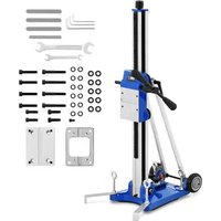
DMS300 - Drill MSW - Free user manual and instructions
Find the device manual for free DMS300 MSW in PDF.


| Product type | Drill stand (drill press) |
| Brand | MSW |
| Model | DMS300 |
| Dimensions (L x D x H) | 400 x 480 x 940 mm |
| Weight | 17.6 kg |
| Max drilling diameter (low speed) | 180 mm |
| Max drilling diameter (high speed) | 300 mm |
| Vertical travel range | 590 mm |
| Transmission ratio | 1:1 |
| Power supply type | Manual (non-motorized stand) |
| Fixation | By vacuum suction pad |
| Carriage | With hole saw carrier |
| Height adjustment system | Adjustment crank |
| Leveling | Bubble levels and leveling screws (x4) |
| Column material | Steel |
| Intended use | Precision drilling with hole saws |
| Required protective equipment | Safety goggles, hearing protection, dust mask, gloves |
| Maintenance | Clean with soft cloth, lubricate guides |
| Storage conditions | Dry and cool place, away from humidity and sun |
| Included accessories | Stabilizer bars, Allen keys, wrenches, screws, adapters, washers |
| Repairability | Repair only by manufacturer's technical service |
Frequently Asked Questions - DMS300 MSW
User questions about DMS300 MSW
0 question about this device. Answer the ones you know or ask your own.
Ask a new question about this device
Download the instructions for your Drill in PDF format for free! Find your manual DMS300 - MSW and take your electronic device back in hand. On this page are published all the documents necessary for the use of your device. DMS300 by MSW.
USER MANUAL DMS300 MSW
A. Säule
B. Libella
natural_image
Close-up of a hand using a tool to adjust or install a blue industrial component, no visible text or symbols.natural_image
Close-up of a blue laboratory vise with metal clamps and a white surface, no visible text or symbolsnatural_image
Close-up of a blue car wheel bracket with metal clamps and black connectors (no visible text or symbols)natural_image
Close-up of a blue mechanical component with a green circular dial on top, no visible text or symbols.natural_image
Close-up of a blue and silver MATT drill press tool with adjustable handle and base (no visible text or symbols)This User Manual has been translated for your convenience using machine translation. Reasonable efforts have been made to provide an accurate translation; however, no automated translation is perfect nor is it intended to replace human translators. The official User Manual is the English version. Any discrepancies or differences created in the translation are not binding and have no legal effect for compliance or enforcement purposes. If any questions arise related to the accuracy of the information contained in the User Manual, please refer to the English version of those contents which is the official version.
Technical data
| Parameter description | Parameter value |
| Product name | DRILLING MACHINE STAND |
| Model | MSW-DMS300 |
| Dimensions [Width x Depth x Height; mm] | 400 x 480 x 940 |
| Weight [kg] | 17.6 |
| For maximum drilling diameter [mm] | Low drilling speed: ø180High drilling speed: ø300 |
| Movement range [mm] | 590 |
| Gear ratio | 1:1 |
1. General Description
This manual is intended to assist you for safe and reliable use. The product is designed and manufactured strictly according to technical specifications using the latest technology and components and maintaining the highest quality standards.
CAREFULLY READ AND UNDERSTAND THIS MANUAL BEFORE STARTING THE WORK.
To ensure long and reliable operation of the device, make sure to operate and maintain it properly in accordance with the guidelines in this instruction manual. The technical data and specifications in this manual are up-to-date. The manufacturer reserves the right to make changes in order to improve the quality. Taking the technical progress and the possibility of reducing noise into account, the unit is designed and built in such a way so that risks resulting from noise emissions are reduced to the lowest possible level.
Explanation of symbols
Read the manual before use.
Recyclable product.
CAUTION! or WARNING! or REMEMBER! describing a situation (general warning sign).
Wear ear protection. Exposure to noise may cause hearing loss.
Wear protective goggles.
Wear a dusk mask (protecting the respiratory tract).
Wear protective gloves.
Wear protective footwear.
Use face protection.
Wear a protective suit.
CAUTION! Danger of crushing your hand!!
CAUTION! The figures in this manual are illustrative only and may vary in some details from the actual appearance of the product.
2. Safety of use

CAUTION! Read all safety warnings and instructions. Failure to follow warnings and actions could result in serious injury or even death.
The term "device" or "product" in the warnings and in the description of the instructions refers to
Drilling Machine Stand
2.1. Safety in the workplace
a) Keep the work area tidy and well lit. Disorder or poor lighting can lead to accidents. Be foresighted, watch what you are doing and use common sense when using the unit.
b) Do not use the unit in an explosive area, for example in the presence of flammable liquids, gases or dust. The devices create sparks that can ignite the dust or fumes.
c) If in doubt as to whether the device is working, contact the manufacturer's technical service.
d) Repairs to the device may only be carried out by the manufacturer's service. Do not attempt to repair the product on your own!
e) No children or unauthorized persons are allowed in the work area. (Inattention may result in loss of control of the unit.)
f) Use the unit in a well-ventilated area.
g) Check the condition of the safety stickers regularly. Replace them if they are illegible.
h) Keep these instructions for use for future reference. If the product is to be handed over to a third party, hand it over with this user manual.
i) Keep packaging components and small installation parts out of the reach of children.
j) Keep the device away from children and animals.
k) When using this product together with other devices, also follow the other instructions for use.

Remember! Keep children and other bystanders safe while operating the equipment.
2.2. Personal safety
a) Do not operate this device if you are tired, ill or under the influence of alcohol, drugs or medication that could impair your ability to operate the device.
b) The unit may be operated by persons who are physically fit, capable of operating it and appropriately trained, and who have read this instruction manual and have been trained in occupational safety and health.
c) Use caution and common sense when operating this unit. A moment's inattention during operation may result in serious personal injury.
d) Use personal protective equipment as required when operating the unit as specified in Section 1 of the explanation of symbols.
The use of appropriate, approved personal protective equipment reduces the risk of injury.
e) Do not overestimate your capabilities. Maintain body balance and equilibrium at all times during operation. This allows for better control of the machine in unexpected situations.
f) Do not wear loose clothing or jewelry. Keep hair, clothing, and gloves away from moving parts. Loose clothing, jewelry, or long hair can be caught in moving parts.
g) Eye, ear, and respiratory protection is recommended.
h) The product is not a toy. Children should be watched to ensure that they do not play with the appliance.
2.3. Safe use of the device
a) Do not overload the device. Use tools that are suitable for the application. A correctly selected product will do a better and safer job for which it was designed.
b) Keep unused product out of the reach of children and anyone unfamiliar with the device or this manual. Products are dangerous when used by inexperienced users.
c) Keep the product in good working order. Check before each use for general damage or damage to moving parts (cracks in parts and components or any other condition that may affect the safe operation of the device). If damaged, have the device repaired before use.
d) Keep the product out of the reach of children.
e) Repairs and maintenance should be carried out by qualified personnel using only original spare parts. This will ensure the safety of use.
f) To ensure the designed operational integrity of the device, do not remove factory-installed covers or loosen screws.
g) When transporting or moving the device from storage to the place of use, observe the health and safety rules for manual handling applicable in the country where the device is used.
h) Clean the device regularly to prevent permanent dirt build-up.
i) The product is not a toy. Cleaning and maintenance must not be performed by children without adult supervision.
j) Do not tamper with the device to alter its performance or design.
k) Keep the unit away from sources of fire and heat.
I) Do not overload the device.
m) Be sure to correctly position the tool holder in the machine.

CAUTION! Although the product has been designed to be safe and has adequate safeguards and despite the additional safety features provided to the user, there is still a slight risk of accident or injury when handling the product. Caution and common sense are advised when using the product.
3. Instructions for use
The product is designed to work with holesaws, affecting their ergonomics and precision of drilling.
The user is responsible for any damage resulting from misuse.
3.1. Product overview
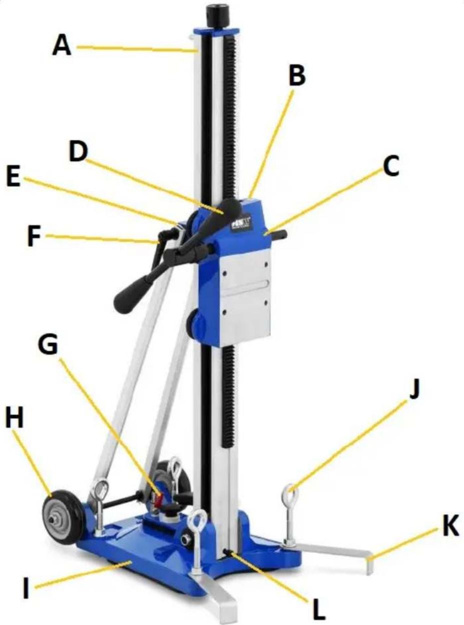
A. Column
B. Libella
C. Trolley with holesaw attachment
D. Height adjustment crank
E. Column stand locking screw (not shown)
F. Lever stabilizing the position of the column stand
G. Pneumatic module with a female end and a valve
H. Wheel
I. Base with a handle (not shown)
J. Base leveling screw (x4)
K. Stabilizers
L. Column lock screw
a. Adapter stabilizing sticks
b. Allen keys
c. Flat wrenches
d. Cylinder head screws
e. Adapters
f. Washers
3.2. Preparation for operation
POSITIONING OF THE UNIT
Keep the appliance away from any hot surfaces. Always operate the appliance on an even and stable surface and out of the reach of children and persons of impaired mental, sensory and intellectual functions. With vacuum mountings, make sure that there is no dirt or other loose elements on the surface to which the stand will be attached, and that the vacuum itself is sufficient to hold the stand and its accessories.
NOTE: do not use vacuum mounts on drilled ceiling, vaulted holes, etc. so overhead positions!
ASSEMBLY OF THE UNIT
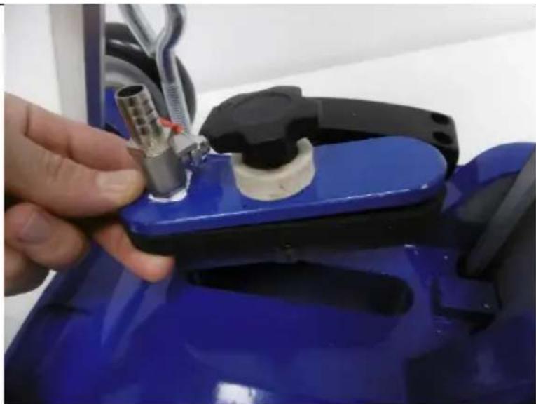
After unpacking the device and disassembling it, attach the vacuum module (G) to the base (I) by tightening it - so that the connection is tight.
natural_image
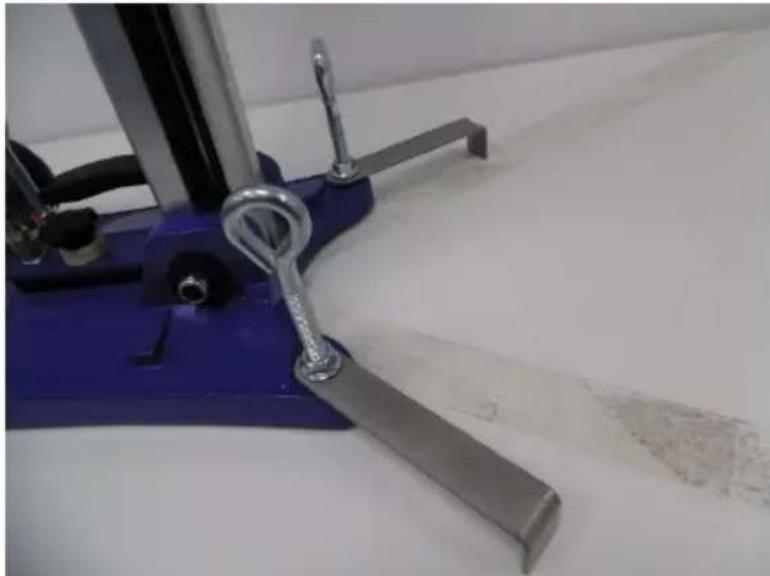
Close-up of a hand using a tool to adjust or install a blue industrial component, no visible text or symbols.Then screw both stabilizers (K) to the base from the front using the leveling screws (J) with the locknuts on them.
natural_image
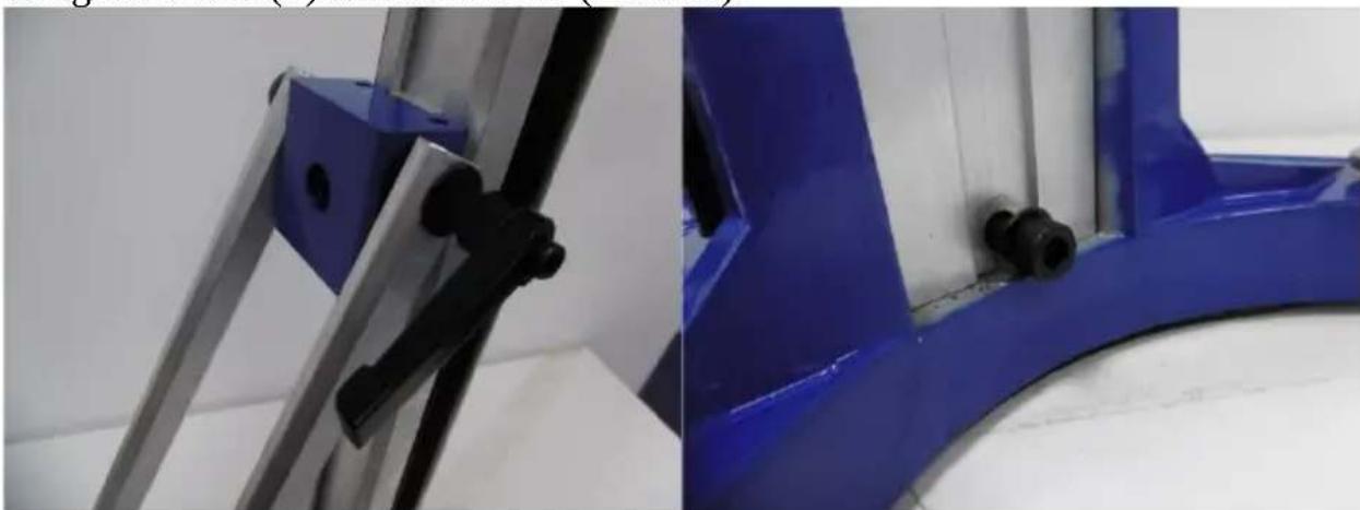
Close-up of a blue laboratory vise with metal clamps and a white surface, no visible text or symbolsSet the column (A) in the final, vertical position and tighten the structures carefully using the levers (F) and the screws (E and L).
natural_image
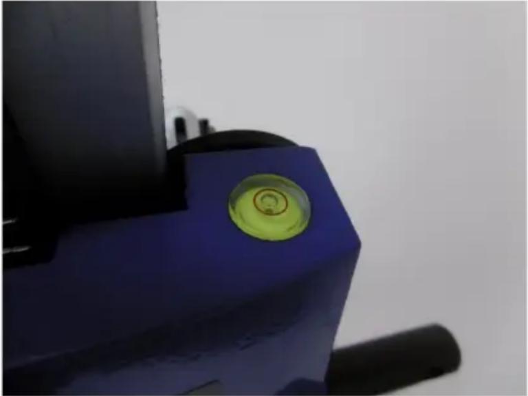
Close-up of a blue industrial component with black bolts and metal bracket (no visible text or symbols)Using the libellas (B), level the structure by turning the leveling screws (J) on the base - tighten their nuts only after leveling.
natural_image
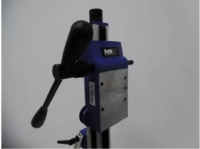
Close-up of a blue mechanical component with a green circular highlight on its surface (no text or symbols visible)Finally, you can attach the drilling machine to the stand - use the included mounting kit if necessary. Connect with the vacuum pump via the pneumatic quick coupler (the male end is located in the base - the pneumatic module). Before first use, lubricate (e.g. with universal grease) the treadmill on the column to ensure smooth and trouble-free operation of the device, in particular, the movement of the trolley.
natural_image
Close-up of a blue industrial machine with black handle and metal frame, no visible text or symbols3.3. Working with the device
- Attach the drilling machine to the trolley (C) of the machine.
- Stabilize the structure using the leveling screws (J) and the libella (B) located on the trolley.
-
Unscrew the inlet valve on the air module (G) and start the pump.
-
After the stand is fully sucked to the ground, if necessary, correct the level (using, among others, a libella).
- Drilling can begin.
3.4. Cleaning and maintenance
a) Use only non-corrosive cleaning agents for cleaning the surfaces.
b) Store the unit in a dry and cool place protected from moisture and direct sunlight.
c) Do not spray the unit with a stream of water or immerse it in water.
d) Perform regular inspections of the unit, checking technical fitness and any damages.
e) Use a soft, damp cloth for cleaning.
f) Do not use sharp and/or metal objects (e.g. wire brush or metal spatula) for cleaning as they may damage the surface of the appliance material.
g) Regularly lubricate the guides and elements on which the trolley moves.
h) Clean the device after each use.

A. Kolumna
B. Libella
natural_image
Close-up of a hand using a tool to adjust or install a blue industrial component, no visible text or symbols.natural_image
Close-up of a blue laboratory clamp with metal bands and a white surface, no visible text or symbolsnatural_image
Close-up of a blue industrial component with black bolts and metal bracket (no visible text or symbols)natural_image
Close-up of a blue mechanical component with a green circular highlight on its surface (no text or symbols visible)natural_image
Close-up of a blue industrial machine with black handle and metal base, no visible text or symbolsnatural_image
Close-up of a hand using a tool to adjust or install a blue industrial component, no visible text or symbols.natural_image
Close-up of a blue laboratory vise with metal clamps and a white surface, no visible text or symbolsnatural_image
Close-up of a blue industrial component with black bolts and metal bracket (no visible text or symbols)natural_image
Close-up of a blue mechanical component with a green circular highlight on its surface (no text or symbols visible)natural_image
Close-up of a blue and black MIST instrument with adjustable handle and base plate (no visible text or symbols)A. Colonne
B. Libelle
natural_image
Close-up of a hand using a tool to adjust or install a blue industrial component, no visible text or symbols.natural_image
Close-up of a blue laboratory vise with metal clamps and a metallic handle, no visible text or symbolsnatural_image
Close-up of two blue industrial metal components with black connectors, no visible text or symbolsnatural_image
Close-up of a blue mechanical component with a green circular highlight on its surface (no visible text or symbols)natural_image
Close-up of a blue industrial machine with black handle and metal frame, no visible text or symbolsA. Colonna
B. Libella
natural_image
Close-up of a hand using a tool to adjust or install a blue industrial component, no visible text or symbols.natural_image
Close-up of a blue laboratory vise with metal clamps and a white surface, no visible text or symbolsnatural_image
Close-up of two blue industrial metal components with black connectors, no visible text or symbolsA. Columna
B. libela
natural_image
Close-up of a hand using a tool to adjust or install a blue industrial component, no visible text or symbols.natural_image
Close-up of a blue laboratory vise with metal clamps and a white surface, no visible text or symbolsnatural_image
Close-up of a blue industrial component with black bolts and metal brackets, no visible text or symbolsA. Oszlop
B. Libella
natural_image
Close-up of a hand using a tool to adjust or install a blue industrial component, no visible text or symbols.natural_image
Close-up of a blue laboratory vise with metal clamps and a white surface, no visible text or symbolsnatural_image
Close-up of a blue industrial component with black bolts and metal brackets, no visible text or symbolsnatural_image
Close-up of a blue mechanical component with a green circular highlight on its surface (no visible text or symbols)natural_image
Close-up of a blue industrial machine with black handle and metal frame, no visible text or symbolsAPPARATETS PLACERING
natural_image
Close-up of a blue mechanical component with a green circular dial on top, no visible text or symbolsnatural_image
Close-up of a blue MIST instrument with adjustable handle and base plate (no visible text or symbols)For the disposal of the device please consider and act according to the national and local rules and regulations.
CONTACT
expondo Polska sp. z o.o. sp. k.

- General Description
- CAREFULLY READ AND UNDERSTAND THIS MANUAL BEFORE STARTING THE WORK.
- Explanation of symbols
- Safety of use
- Safety in the workplace
- Personal safety
- Safe use of the device
- Instructions for use
- Product overview
- Preparation for operation
- POSITIONING OF THE UNIT
- ASSEMBLY OF THE UNIT
- Working with the device
- Cleaning and maintenance
- APPARATETS PLACERING
- CONTACT
Brand : MSW
Model : DMS300
Category : Drill