UNI_HEATER_10 - Heating Uniprodo - Free user manual and instructions
Find the device manual for free UNI_HEATER_10 Uniprodo in PDF.

| Product type | Wall-mounted ceramic fan heater |
| Model | UNI_HEATER_10 |
| Supply voltage | 230 V~ / 50 Hz |
| Nominal power | 1000 – 2000 W (min – max) |
| Protection class | II (double insulation) |
| IP rating | IPX2 |
| Dimensions (W x D x H) | 535 x 110 x 195 mm |
| Weight | 2.4 kg |
| Adjustable temperature range | 10 – 49 °C |
| Recommended heating area | 10 – 15 m² |
| Remote control | Yes, with CR2025 3V battery |
| Timer (auto-off) | 1 – 12 hours |
| Weekly timer | Yes, up to 6 programs per day |
| Open window detection | Yes |
| Minimum mounting height | 2.05 m from floor |
| Operating mode | Cold fan, low heat, high heat |
| Air flap function | Yes, adjustable |
| Maintenance and cleaning | Unplug, let cool, damp cloth |
| Remote control battery type | CR2025 3V |
Frequently Asked Questions - UNI_HEATER_10 Uniprodo
User questions about UNI_HEATER_10 Uniprodo
0 question about this device. Answer the ones you know or ask your own.
Ask a new question about this device
Download the instructions for your Heating in PDF format for free! Find your manual UNI_HEATER_10 - Uniprodo and take your electronic device back in hand. On this page are published all the documents necessary for the use of your device. UNI_HEATER_10 by Uniprodo.
USER MANUAL UNI_HEATER_10 Uniprodo
UNI_HEATER_10
DE


natural_image
Close-up of a white electric fan or air conditioner unit with ventilation grilles and mounting holes, showing red arrows pointing to the ports (no text or symbols visible)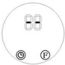

WICHTIG!


This User Manual has been translated using machine translation. We have made every effort to ensure the translation is accurate, but please note that automated translations are not perfect and are not meant to replace human translators. The official version of the User Manual is in English. Any differences between the translated version and the original English are not legally binding. If you have any questions about the accuracy of the translation, please refer to the English version, which is the official reference. More language versions are available upon request via info@expondo.com.
Technical Data
| Parameter description Parameter value | ||
| Product name Ceramic wall heater | ||
| Model | UNI_HEATER_09 | UNI_HEATER_10 |
| Supply voltage [V~] / Frequency [Hz] | 230/50 | |
| Rated power [W] 1000-2000 (min-max) | ||
| Safety class | II | |
| IP class IP22 IPX2 | ||
| Dimensions [width x depth x height; mm] | 510 x 120 x 230 535 x 110 x 195 | |
| Weight [kg] 2.4 2.4 | ||
| Temperature control range [°C] | 10-49 | |
| Remote control Yes | ||
| Battery type for the remote CR | 2025 3V | |
| Heating area [m2] | 10-15 | |
1. General Description
This manual is intended to assist you for safe and reliable use. The product is designed and manufactured strictly according to technical specifications using the latest technology and components and maintaining the highest quality standards.
CAREFULLY READ AND UNDERSTAND THIS MANUAL BEFORE STARTING THE WORK.
To ensure long and reliable operation of the device, make sure to operate and maintain it properly in accordance with the guidelines in this instruction manual. The technical data and specifications in this manual are up-to-date. The manufacturer reserves the
right to make changes in order to improve the quality. Taking the technical progress and the possibility of reducing noise into account, the unit is designed and built in such a way so that risks resulting from noise emissions are reduced to the lowest possible level.
Explanation of symbols
 | The product complies with applicable safety standards. |
 | Read the manual before use. |
 | Recyclable product. |
 | CAUTION! or WARNING! or REMEMBER! Describing a situation (general warning sign). |
 | CAUTION! Risk of electric shock! |
 | Safety class II equipment with double insulation. |
 | Caution! Hot surface can cause burns! |
 | For indoor use only. |
 | Do not cover the unit with any materials or objects. |

CAUTION! The figures in this manual are illustrative only and may vary in some details from the actual appearance of the product.
2. Safety of use

CAUTION! Read all safety warnings and instructions. Failure to follow the warnings instructions may result in electric shock, fire and/or serious injury or death.
The term "device" or "product" in the warnings and in the description of the instructions refers to
Ceramic wall heater.
2.1. Electrical safety
a) The plug of this device must fit into the outlet. Do not modify the plug in any way. Original plugs and matching outlets reduce the risk of electric shock.
b) Avoid touching grounded parts, such as pipes, heaters, ovens, and refrigerators. There is an increased risk of electric shock if your body is grounded and touches the device while exposed to direct rain, wet pavement, or while working in a damp environment. If water enters the device, there is an increased risk of damage to the unit and electric shock.
c) Do not touch the device with wet or damp hands.
d) Do not use the cord in an unintended manner. Never use it to carry the device or to pull the plug out of the socket. Keep the cord away from heat sources, oil, sharp edges or moving parts. Damaged or tangled cords increase the risk of electric shock.
e) If you cannot avoid using the product in a wet environment, use a residual current device (RCD) to connect it to electrical mains. Using an RCD reduces the risk of electric shock.
f) Do not use the device if the power cord is damaged or shows signs of wear. A damaged power cord should be replaced by a qualified electrician or the manufacturer's service department.
g) To avoid electric shock, do not immerse the cable, plug, or the device itself in water or other liquid. Do not use the appliance on wet surfaces.
h) CAUTION – DANGER TO LIFE! When cleaning or using the appliance, never immerse it in water or other liquids.
i) Do not use the appliance in rooms with very high humidity / in the immediate vicinity of water tanks!
j) Do not allow the machine to get wet. Risk of electric shock!
2.2. Safety in the workplace
a) If you find any damage or irregularities in the operation of the product, immediately turn it off and report it to an authorized person.
b) If you have any doubts as to whether the product is working properly or if it is damaged, contact the manufacturer's service department.
c) Repairs to the device may only be carried out by the manufacturer's service. Do not attempt to repair the product on your own!
d) In the event of ignition or a fire, use dry powder or CO2 extinguishers only to suppress the fire of the appliance is live.
e) Check the condition of the safety stickers regularly. Replace them if they are illegible.
f) Keep these instructions for use for future reference. If the product is to be handed over to a third party, hand it over with this user manual.
g) Keep packaging components and small installation parts out of the reach of children.
2.3. Personal safety
a) Do not operate this device if you are tired, ill or under the influence of alcohol, drugs or medication that could impair your ability to operate the device.
b) The device is not intended to be used by persons (including children) with reduced mental, sensory or intellectual functions or persons who lack experience and/or knowledge unless they are supervised or have been instructed by a person responsible for their safety on how to operate the device.
c) To prevent accidental start-up, make sure the switch is in the off position before connecting to a power source.
d) The product is not a toy. Children should be watched to ensure that they do not play with the product.
e) Do not place your hands or any objects inside the running device!
2.4. Safe use of the device
a) Do not use the device if the ON/OFF switch does not function properly (does not turn on and off). Units that cannot be controlled by the switch are unsafe, cannot operate, and must be repaired.
b) Disconnect the device from the power supply before adjusting, cleaning, or servicing. This precaution reduces the risk of accidental start-up.
c) Keep unused product out of the reach of children and anyone unfamiliar with the device or this manual. Products are dangerous when used by inexperienced users.
d) Keep the product in good working order. Check before each use for general damage or damage to moving parts (cracks in parts and components or any other condition that may affect the safe operation of the device). If damaged, have the device repaired before use.
e) Repairs and maintenance should be carried out by qualified personnel using only original spare parts. This will ensure the safety of use.
f) To ensure the designed operational integrity of the device, do not remove factory-installed covers or loosen screws.
g) When transporting or moving the device from storage to the place of use, observe the health and safety rules for manual handling applicable in the country where the device is used.
h) Do not touch any moving parts or accessories unless the device is unplugged.
i) Do not move, shift, or rotate the device while in operation.
j) Clean the device regularly to prevent permanent dirt build-up.
k) Do not obstruct the air inlet or outlet.
I) The product is not a toy. Cleaning and maintenance must not be performed by children without adult supervision.
m) Do not tamper with the device to alter its performance or design.
n) Keep the unit away from sources of fire and heat.
o) Do not block the ventilation openings of the unit!

CAUTION! Although the product has been designed to be safe and has adequate safeguards and despite the additional safety features provided to the user, there is still a slight risk of accident or injury when handling the product. Caution and common sense are advised when using the product.
3. Instructions for use
The product is intended for room heating.
The user is responsible for any damage resulting from misuse.
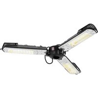
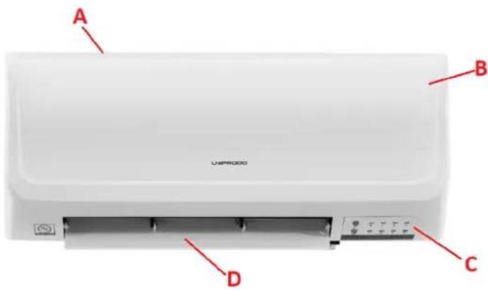
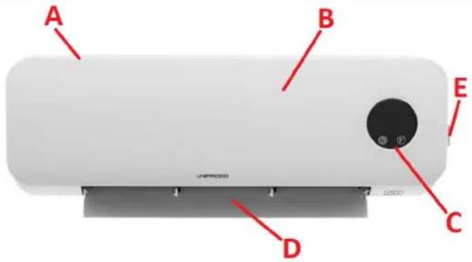
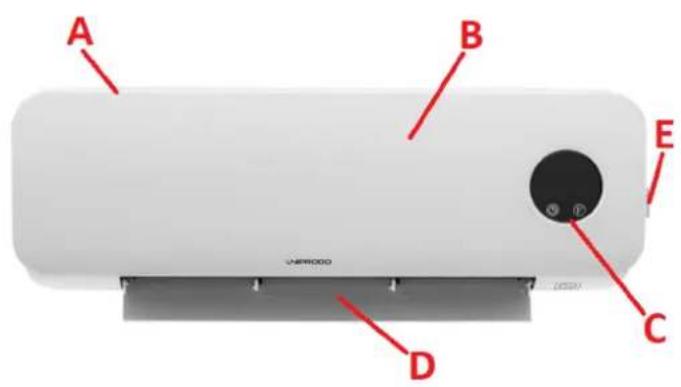
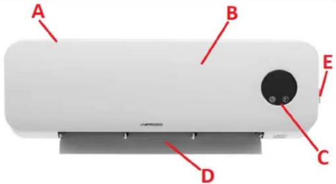
3.1. Product overview
UNI_HEATER_09
EN
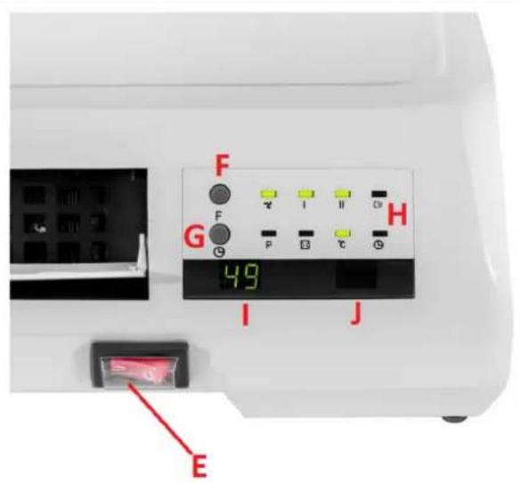
UNI_HEATER_10


A. Air intake / ventilation inlet (not shown)
B. Casing
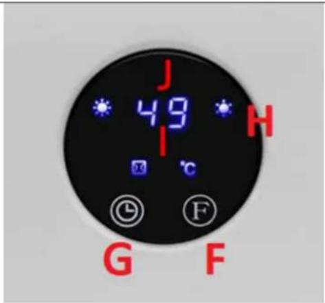
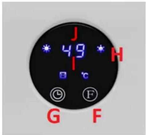
C. Display and control panel
D. Air supply outlet with control flap
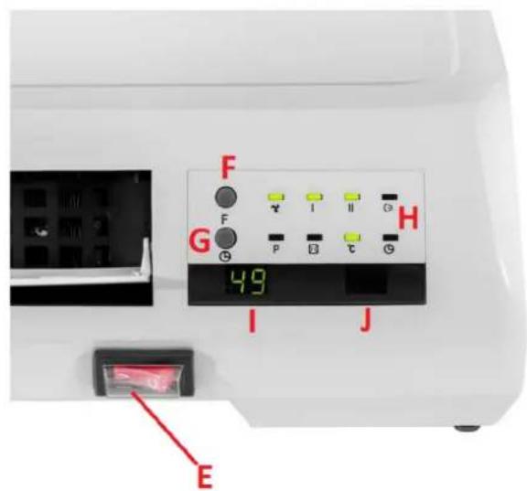
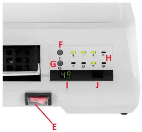
E. Power switch
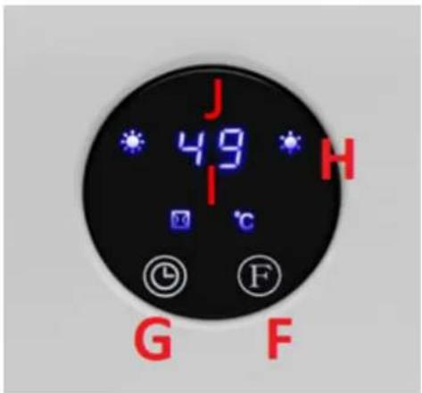
F. Function selection button
G. Timer button
H. Device control lamps
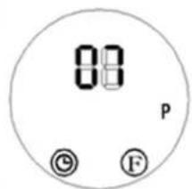
I. Display
J. Receiver for the remote control
3.2. Preparation for operation
POSITIONING OF THE UNIT
The ambient temperature must not exceed 40^ C and ambient humidity should not exceed 85%. The unit should be mounted on a vertical, stable wall in a way that ensures good air circulation. Keep the unit away from any hot and humid surfaces. Always operate the unit on a stable, clean, fireproof and dry surface and out of the reach of children and persons with impaired mental, sensory and intellectual functions. It is forbidden to use the device in the immediate vicinity of bathtubs,
showers, swimming pools! Place the unit in such a way that the mains plug can be reached at any time. Ensure that the power supply to the unit corresponds to that specified on the identification plate! During installation, the building and installation regulations in force in a given region should also be taken into account.
ASSEMBLY OF THE DEVICE
Attach the device to a vertical wall with expansion bolts and special catches/hooks - use the special holes on the back of the device (see the pictures below).
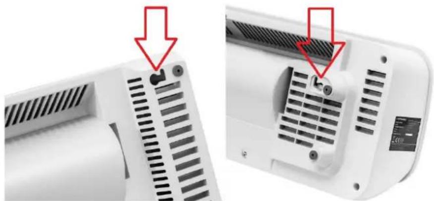
natural_image
Close-up of a white electronic device showing ventilation grilles and a side-mounted fan (no text or symbols visible)The minimum height of the mounting holes from the floor should be 1.8 m for the UNI_HEATER_09 model and 2.05 m for the UNI_HEATER_10 model.
3.3. Working with the device
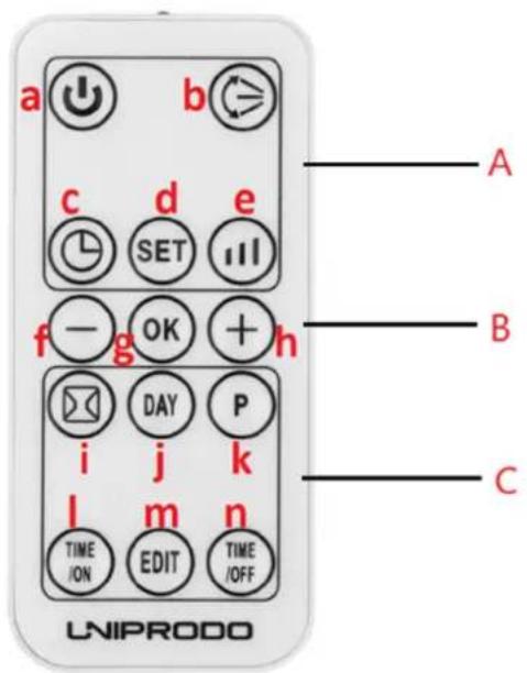
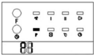
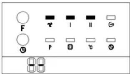
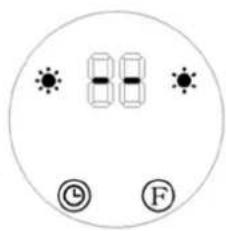
A. Standard function zone
B. General function zone
C. Window detection and weekly timer function zone
a) Device on/off button
b) Air supply flap start/stop button
c) Timer on/off button
d) Time and day setting button
e) Heating level button
f) Button for decreasing the value of a given parameter
g) Button for confirming a given parameter
h) Button for increasing the value of a given parameter
i) Open window detection on/off button
j) Day selection button (for automatic operation)
k) Automatic operation programming start button
I) Auto-on button
m) Edit button
n) Automatic shutdown setting button
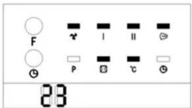
3.3.1 Startup
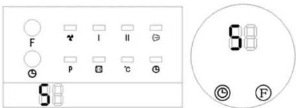
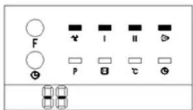
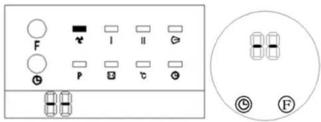
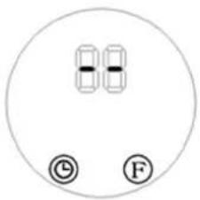
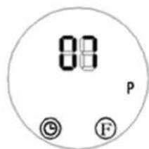
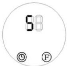
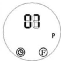
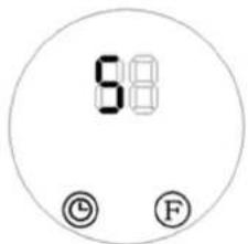
- Connect the device to the power socket and set the power switch (E) to the "I" position - the device will go into standby mode and the display (I) will show the message "S as shown below.
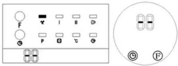
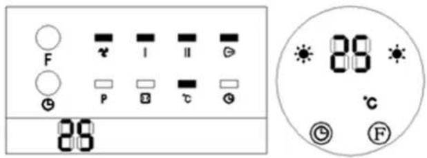
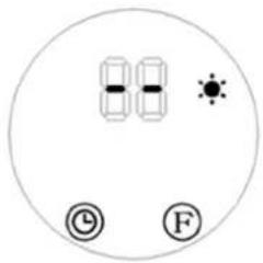
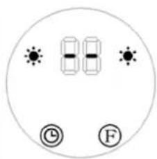
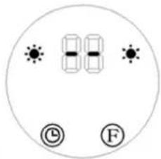
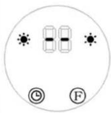
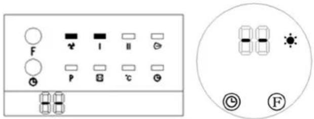
- Press the function selection button (F) once on the control panel: The product operates in "cool wind" mode. The display will show the value "-" (see pictures below) and the model's fan-indicator will light up (see the picture below on the left):
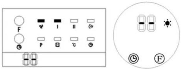
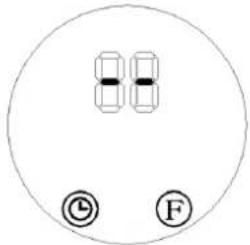
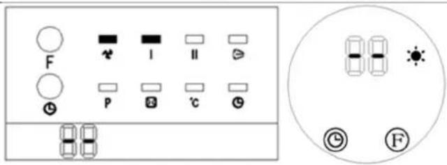
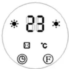
- Press the function selection button (F) twice: The product operates in "low heat" mode (see pictures below):
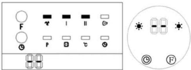
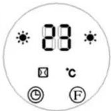
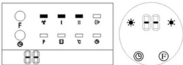
- Press the function selection button (F) three times: The product operates in "high heat" mode (see pictures below):
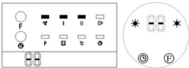
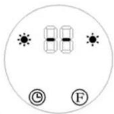
- Press the function selection button (F) four times: In addition to operate in "high heat" mode, the product will additionally activate the airflow flap (D). Activation of the airflow flap in the model will be additionally signaled by an additional indicator (see the picture below):
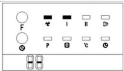
- Press the function selection button (F) five times: The product returns to standby mode. The value "−" will appear on the display of the control panel, the same as after pressing the function selection button (F) once (see the picture below). The product will continue blowing cool wind for 30 seconds as a delay.
EN
3.3.2 Timer setting
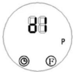
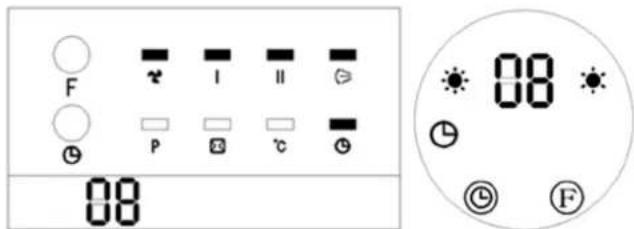
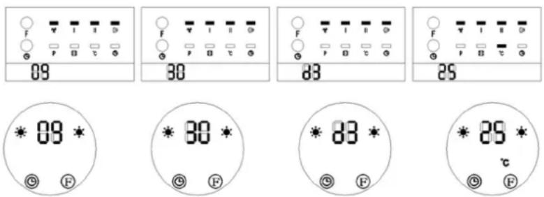
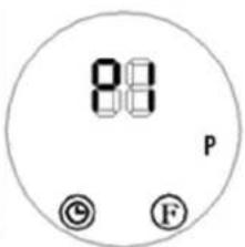
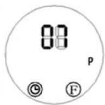
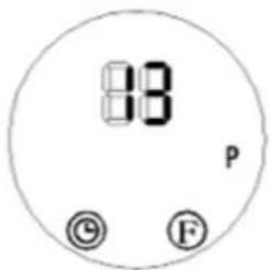
Press the timer button “” on the control panel (G) or the remote control (C) to set the timer from 01-12 hours to indicate automatic shutdown. Each press of this button increases the time by 1 hour. After setting the time, the display will show the currently set time for 5 seconds. Then the display will revert to showing the previous value, and the timer indicator “” lights up. (See the pictures below, e.g. timer set to 8 hours)
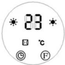
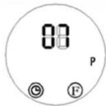
3.3.3 Setting the switch-on time
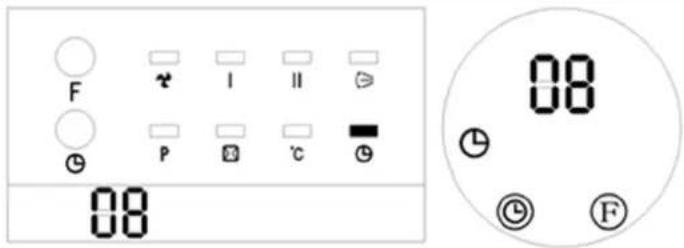
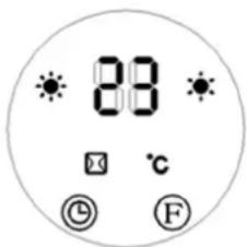
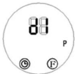
In standby mode, press the timer button “” on the control panel (G) or the remote control (C) to set the delay time for the automatic start-up of the unit in the range of 1-12 hours. Once set, the display will show the time to switch-on and the timer indicator “” will be illuminated. The remaining time will be indicated with a countdown every hour. After the set time has elapsed, the device will start up with the default temperature of 23^ C. (See the pictures below, e.g. scheduled to start in 8 hours)
EN

NOTICE! In the absence of a specific temperature and weekly timer setting,
the unit will turn off after 12 hours of continuous operation and enter standby mode.
3.3.4 Controlling the device with the remote control

NOTICE! During remote control operation, ensure that the remote control transmitter is aimed directly at the product's remote control receiving area to avoid unresponsive operation.
- Press the on/off button "①" on the remote control (a) to turn on the unit and trigger the "cool wind" mode. The display will show the value "JL (see pictures below) and the fan indicator will be additionally illuminated. (see the picture below left)
- Press the heating level button (e) “☐” once: The product operates in “low heat” mode, with the digital display showing “-” and the corresponding indicator “●” lighting up. (see pictures below)
EN
- Press the heating level button (e) “” twice: The product operates in "high heat" mode, with both "low heat" and "high heat" indicators “” ht. (see pictures below)
-
Press the heating level button (e) again to turn off the heating, ventilation will stop after approx. 30 seconds and the device will go into standby mode.
-
The function of the timer button (c) works in the same way as from the control panel (see the description above).
-
The air supply flap button (b) “(≥)”: Switch it on by pressing it once. Press again to switch it off. In the Model, the activation of the flap is confirmed by the corresponding indicator on the control panel - the same icon as on the button of this function on the remote control.
3.3.5 Setting current time/day

NOTICE! The settings can be changed both in standby mode and during on.
- Press the time and day setting button (d) "SET" on the remote control, and the display will flash and show the default value "12". Use the
parameter decrease “” increase “” (f/b) buttons to set the current hour (24-hour format).
- Press the time and day setting button (d) “SET” again to move to the minute setting. The display will show the default value "30". Use the parameter decrease “7increase” (f/d) buttons to set the current minute (selection range 00-59).
- As soon as you set the time, press the time and day setting button (d) "SET" again to choose the current day of the week. The display will show the message "d7" as default, where:
d1 = Monday; d2 = Tuesday, d3 = Wednesday, etc. until Sunday = d7.
Set the current day of the week by using the parameter decrease “increase” (f/n) buttons. Then use the button for confirming the value (g) “to approve the selected values. The display will revert to showing the previous information as before changing the settings.
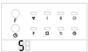
For example, if we set Wednesday, 9:30 a.m., heating at 25^ C with high heat, the setting diagram will look like this for a given model:

IMPORTANT!
- The set time and day will be retained in standby mode. If the main power is turned off or there is a power outage, the settings must be reconfigured. e.g. sudden disconnection of the power plug from the socket.
- To check the currently set day and time, press the time and day setting button (d) "SET"
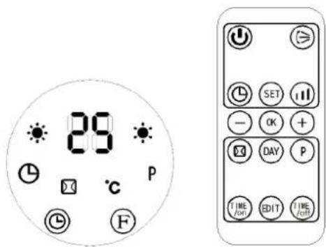
3.3.5 Setting the temperature or canceling the setting
- While operating, press the button to increase “⊕” or decrease “⊖” the value of a given parameter (h/f), and the display will show the default temperature setting “23
- The same buttons on the remote control (h/f) “⊕” or “⊖” can be used to set a different target temperature within the allowable range (10–49°C).
- Use the value confirmation button (g) "OK" to save the newly set value that is currently displayed.
e.g. Setting temperature to 25^ C with a current ambient temperature of 15^ C.
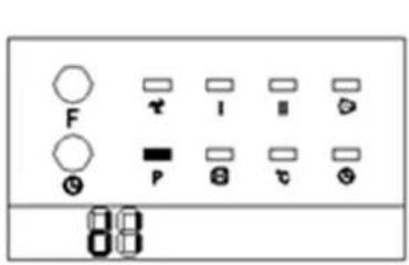
- To delete the previously set temperature, press the heat level button (e) "to select one of the two available heating levels (described earlier).
Then the display will show "and the temperature light" will turn off, while the indicator of the selected heating level will still be illuminated.

IMPORTANT! After 12 hours of continuous operation in one of these two modes, the device will turn off automatically (the fan will continue to run for 30 seconds) and will go into standby mode.
3.3.6 Remarks on temperature settings and operation of the device
EN
- If the difference between the set temperature and the ambient temperature is >2^ , the unit works at full power. If this difference is <2^ , the unit operates at lower power.
- When the temperature set on the unit is equal to the ambient temperature, the fan will run for another 30 seconds to cool down the unit inside and then the unit will go into standby mode.
- When the temperature in the ambient standby mode drops below 2°C in relation to the temperature set on the device, it will turn on automatically and start heating.
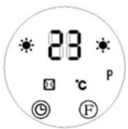
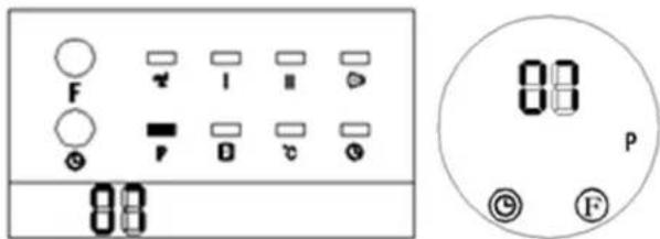
3.3.7 Setting the weekly program
1) Press the on/off button "to enter operating mode.
2) Set the current time and day as described above (see more under the section "Setting current time/day").
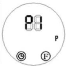
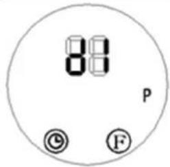
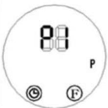
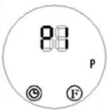
3) Press the automatic operation programming start button (k) “P” on the remote control. The weekly indicator "P" will light up, indicating the activation of the weekly timer setting. (See the picture below)
4) Press the day mode button (j) "DAY" and the display will show "d1" to "d7" (the corresponding day of the week, i.e. Monday to Sunday). Select a specific day of the week, e.g. Monday = "d1 Tuesday = "", d2c.:
5) With the selected day, press the button for editing the day of the week (m)
“EDIT,” and the display will show up to 6 available time programs (P1-P6) for that day. To set the first segment, the display will show as follows:
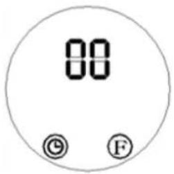
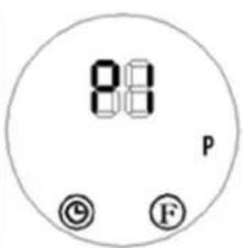
6) Press the auto-on setting button (I) "TIME/ON" to select the time to start the unit. The digital display will default to "00". Continue pressing the button to set the desired start time (24-hour format). E.g. to set a start time of 7:00 a.m., the display will show as follows:

7) Press the auto-off button (n) “TIME OFF” and the display will default to the previously set auto-off time. Continue pressing the button to set the desired end time (24-hour format). E.g. to set an end time of 1:00 p.m., the display will show as follows:

NOTICE! The TIME/OFF " (end time) cannot be earlier than
the TIME/ON “” (start time). Setting the same switch-on and switch-off time will put the device into standby mode.
8) Repeat steps 4 to 7 to configure the working start and end times for each day of the week (Monday to Sunday).
9) After completing the setup, press the day mode button (j) “DAY” to choose the desired workdays and press the edit button (m) “EDIT” to select the specific time periods for each day. Use the parameter decrease “/increase” (f/B) buttons to set the working temperature (range: 10–49°C).

NOTICE! Once the weekly timer setting is enabled, you can use the
day mode button (j) “” and the edit button (m) “” to check the configured times for each day and time period.
10) Press the automatic operation programming start button (k) “P” to deactivate the automatic weekly timer setting (the corresponding indicator "P" on the control panel will be off). Once deactivated, the device will revert to its previous operating state.

NOTICE! When encountering a power outage, the weekly timer is will need to be reconfigured.
UNI HEATER 09
11) [Only for ] After programming the previous steps according to the above, press the day selection button (j) to set the day of the week to start the automatic operation. Then select the time of switching on with the edit button (m). With the buttons for increasing and decreasing the value of a parameter (h or f), select the target temperature and save it in the device's memory with the confirmation button (g).

IMPORTANT!
- During automatic weekly operation according to the programmed schedule, pressing the buttons (j, l, m, n) allows you to check the time settings for a specific day and its set time interval program.
- If no specific heating temperature is set, its default value is 23^ . However, when the ambient temperature is higher than that set on the device, it will not start up.
- When the power is turned off, the automatic weekly program will be lost.
3.3.8 "Open window" detection function
1) Activating operation mode
- Press the device on/off button (a) “①” to enter operating mode. Warm up the device (it must work a period of time on heating).
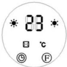
2) Enabling window detection
- Press the open window detection on/off button (i) “” on the remote control. The “” and “” indicators will light up, and the digital display will default to 23°C, showing as “”.
- Use the parameter decrease “ ”/increase “ ” (f/h) buttons to set the working temperature as needed.
EN
- When the window detection function is enabled, if the product detects a temperature drop of 5–10°C within 10 minutes, it will stop heating and enter standby mode within 30 minutes.
• To restart the product, press the device on/off button (a) “💡” on the device or remote control.
- To disable the window detection function, press the open window detection on/off button (i) " again. The " indicator will turn off, and the product will revert to its previous operating state.
e.g. If the ambient temperature is below 23^ C and the window detection function is enabled with a set temperature of 23^ C, the display will appear as shown below.
3) Interaction with weekly timer function
- If both the window detection and weekly timer functions are enabled, the product will not start during the off-periods set by the weekly timer.
- If the product is already operating during a weekly timer period, it will operate based on the temperature set for the window detection function. (See the picture below)

NOTICE! When enabling the weekly timer function, ensure the workdays and time periods are properly configured. If no configuration is set, the weekly timer defaults to 00 (i.e. inactive).
3.4. Cleaning and maintenance
a) Pull the mains plug and let the unit cool down completely before cleaning, adjusting or replacing accessories and when the unit is not in use.
- Wait until the rotating parts stop.
b) Use only non-corrosive cleaning agents for cleaning the surfaces.
c) Do not spray the unit with a stream of water or immerse it in water.
d) Make sure that no water enters through the ventilation openings in the casing.
e) Clean the ventilation openings with a brush and compressed air.
f) Use a soft, damp cloth for cleaning.
g) Remove the battery from the appliance if you do not intend to use it for a long time.
h) Do not use sharp and/or metal objects (e.g. wire brush or metal spatula) for cleaning as they may damage the surface of the appliance material.
i) Do not clean the device with acidic substances, medical products, thinners, fuel, oil or other chemicals as this may damage the device.
j) In case the device does not fully respond to the remote control, check the condition of the battery and, if necessary, replace it with a new, functional one.
To replace the batteries of the remote control, press the latch of the battery compartment (at the bottom of the remote control at its back) and pull out the compartment with the battery. When replacing the battery, pay attention to the correct polarity according to the diagram on the back of the remote control housing.
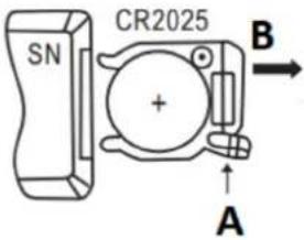
INSTRUCTIONS FOR THE SAFE DISPOSAL OF BATTERIES.
A CR 2025 3V battery is installed in the remote control.
Remove used batteries from the unit in the same way you put them in.
Return the batteries to a unit responsible for their disposal.
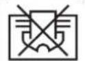
DISPOSAL OF WASTE APPLIANCES
At the end of its useful life, this product should not be disposed of with normal household waste but should be taken to a collection point for the recycling of electrical and electronic equipment. This is indicated by the symbol on the product, operating instructions or packaging. The materials used in this appliance are recyclable according to their marking. By reusing, recycling or applying other forms of use of waste machines, you make a significant contribution to the protection of our environment.
Your local administration will provide you with information about the appropriate disposal point for used appliances.

UWAGA! The figures in this manual are illustrative only and may vary in some details from the actual appearance of the product.

UNI_HEATER_10
PL


natural_image
Close-up of a white electric fan or air conditioner unit with ventilation grilles and mounting holes, showing red arrows pointing to the ports (no text or symbols visible)
natural_image
Close-up of a white electronic device showing ventilation grilles and a side-mounted fan (no text or symbols visible)
UNI_HEATER_10
FR


natural_image
Close-up of a white electric fan or air conditioner unit showing vent slots and ventilation grilles, with red arrows pointing to the ports (no text or symbols visible)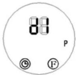


UNI_HEATER_10
IT


natural_image
Close-up of a white electric fan or air conditioner unit showing ventilation grilles and mounting points (no text or symbols visible)

IMPORTANTE!

UNI_HEATER_10
ES


natural_image
Close-up of a white electric fan or air conditioner unit showing ventilation grilles and mounting points (no text or symbols visible)

UNI_HEATER_10
HU

natural_image
Close-up of a white electric fan or air conditioner unit with ventilation grilles and red arrows pointing to the ports (no text or symbols visible)


A. Luftindtag/ventilationsindtag (ikke vist)
B. Kabinet
APPARATETS PLACERING
natural_image
Close-up of a white electronic device showing ventilation grilles and a side-mounted fan (no text or symbols visible)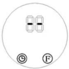
UNI_HEATER_10

natural_image
Close-up of a white electric fan with ventilation grilles and mounting holes, showing red arrows pointing to the component (no text or symbols visible)

UNI_HEATER_10
NL


natural_image
Close-up of a white electronic device showing ventilation grilles and a side-mounted fan (no text or symbols visible)3.3.2 Timerinstelling

UNI_HEATER_10


natural_image
Close-up of a white electronic device showing ventilation grilles and a side-mounted fan (no text or symbols visible)- Trykk én gang på varmenivåknappen (e ⏻) “”: Produktet fungerer i “lav varme”-modus, med det digitale displayet som viser--“” og den tilsvarende indikatoren 🌐 lyser. (se bilder under)
NO

3.3.7 Stille inn ukeprogram

UNI_HEATER_10

A. Luftintag/ventilationsintag (ej visat)
B. Hölje
PLACERING AV APPARATEN
natural_image
Close-up of a white electronic device showing ventilation grilles and a close-up view of the interior panel (no text or symbols visible)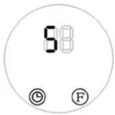

UNI_HEATER_10
PT

natural_image
Close-up of a white electric fan or air conditioner unit with ventilation grilles and mounting holes, showing red arrows pointing to the ports (no text or symbols visible)

UNI_HEATER_10


A. Vstup vzduchu / vstup ventilácie (nezobrazené)
B. Puzdro
natural_image
Close-up of a white electronic device showing ventilation grilles and a fan blade (no text or symbols visible)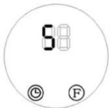
3.3.2 Nastavenie časovača


UNI_HEATER_10
BG


natural_image
Close-up of a white electronic device showing ventilation grilles and a side-mounted fan (no text or symbols visible)A. Стандартна функционална зона

ВАЖНО!

UNI_HEATER_10
EL

natural_image
Close-up of a white electric fan or air conditioner unit with ventilation grilles and mounting holes, showing red arrows pointing to the ports (no text or symbols visible)

ΣΠΟΥΔΑΙΟΣ!


HR

UNI_HEATER_10

natural_image
Close-up of a white electronic device showing ventilation grilles and a side-mounted fan (no text or symbols visible)Minimalna visina otvora za montažu od poda trebala bi biti 1,8 m za model UNI_HEATER_09 i 2,05 m za model UNI_HEATER_10.
3.3. Rad s uređajem

A. Zona standardne funkcije

- Dvaput pritisnite tipku F za odabir funkcije (): Proizvod radi u načinu rada "slaba toplina" (pogledajte slike ispod):

- Pritisnite gumb F za odabir funkcije () tri puta: Proizvod radi u načinu rada "visoke topline" (pogledajte slike ispod):

- Pritisnite tipku F za odabir funkcije () četiri puta: Osim rada u načinu rada "visoke topline", proizvod će dodatno aktivirati zaklopku za protok zraka (D). Aktiviranje zaklopke za protok zraka u modelu dodatno će signalizirati dodatni indikator (vidi sliku ispod):

3.3.2 Podešavanje mjerača vremena
6) Pritisnite tipku za podešavanje automatskog uključivanja (I TIME /ON) "" za odabir vremena za pokretanje jedinice. Digitalni zaslon će prema zadanim postavkama biti "00". Nastavite pritiskati tipku za postavljanje željenog vremena početka (24-satni format). Npr. za postavljanje vremena početka na 7:00 ujutro, zaslon će prikazati sljedeće:
LT

UNI_HEATER_10

natural_image
Close-up of a white electronic device showing ventilation grilles and a fan blade assembly (no text or symbols visible)


UNI_HEATER_10


natural_image
Close-up of a white electronic device showing ventilation grilles and a side-mounted fan (no text or symbols visible)A. Zona de functionare standard

UNI_HEATER_10


A. Dovod zraka/dovod prezračevanja (ni prikazano)
B. Ohišje
natural_image
Close-up of a white electronic device showing ventilation grilles and a side-mounted fan (no text or symbols visible)Najmanjša višina montažnih lukenj od tal naj bo 1,8 m za model UNI_HEATER_09 in 2,05 m za model UNI_HEATER_10.
3.3. Delo z napravo

- Priključite napravo v električno vtičnico in nastavite stikalo za vklop (E) v I položaj "" - naprava bo prešla v stanje pripravljenosti in na zaslonu (I) se bo prikazalo sporočilo S "", kot je prikazano spodaj.
- Dvakrat pritisnite gumbF za izbiro funkcije (): Izdelek deluje v načinu "nizke toplote" (glejte slike spodaj):
- Trikrat pritisnite gumbF za izbiro funkcije (): Izdelek deluje v načinu "high heat" (glejte spodnje slike):
- Štirikrat pritisnite gumbF za izbiro funkcije (): Poleg delovanja v načinu »high heat« bo izdelek dodatno aktiviral loputo za pretok zraka (D). Aktiviranje lopute za pretok zraka v modela be dodatno signaliziral dodatni indikator (glej spodnjo sliko):

- Enkrat pritisnite tipko za stopnjo ogrevanja (e ^111 ) "": Izdelek deluje v načinu "nizke toplote", pri čemer digitalni prikazovalnik prikazuje -- "" in ustrezen indikator sveti. (glej slike spodaj)
SL

- Dvakrat pritisnite gumb za stopnjo ogrevanja (e 📄) "": Izdelek deluje v načinu "high heat", pri čemer svetita indikatorja 🎟"nizka toplota 🎟" in "visoka toplota" "" (glej slike spodaj)

For the disposal of the device please consider and act according to the national and local rules and regulations.
CONTACT
expondo Polska sp. z o.o. sp. k.