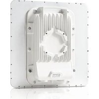
PTP 550e - Telecommunication Equipment Cambium Networks - Free user manual and instructions
Find the device manual for free PTP 550e Cambium Networks in PDF.


| Product Type | 5 GHz Outdoor Point-to-Point Radio |
| Brand | Cambium Networks |
| Model | PTP 550e |
| Frequency Bands | 5 GHz: 5470-5725 MHz and 5725-5875 MHz (depending on country) |
| Maximum Power (EIRP) | 30 dBm (1 W) in 5470-5725 MHz, 36 dBm (4 W) in 5725-5875 MHz |
| Antenna | Integrated 23 dBi or connector for external antenna (max gain 40 dBi) |
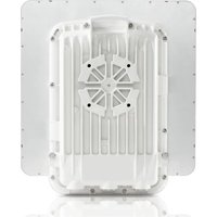
| Interfaces | 1 RJ45 Ethernet port (PoE 802.3at), 1 SFP port, 2 N connectors (connected ODU) |
| Power Supply | PoE 802.3at via included indoor power supply unit (PSU) |
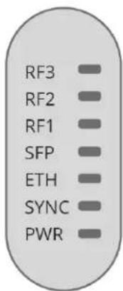
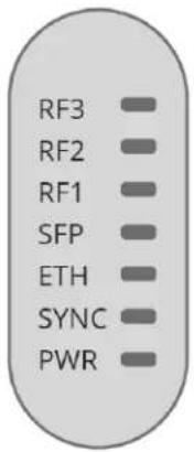
| LED Indicators | PWR (red), SYNC (yellow), ETH (red/green/orange), SFP (red/green/orange), RF 1-3 (signal strength) |
| Management | Web interface (HTTP), default IP address 169.254.1.1, credentials admin/admin |
| Integrated ODU Kit Contents | 23 dBi ODU, PSU, mounting bracket, power cord |
| Connected ODU Kit Contents | Connected ODU, mounting bracket, PSU, power cord |
| Safety | Minimum distance 10 cm, mandatory grounding, lightning protection |
| Installation | Professional recommended; configure region and country code |
| Maintenance | Disconnect before servicing; avoid contact during operation (hot surface) |
| Compliance | Directive 2014/53/EU, WEEE |
| Intended Use | Fixed outdoor professional point-to-point links |
| Online Resources | User guide and quick start guide: support.cambiumnetworks.com/guides |
Frequently Asked Questions - PTP 550e Cambium Networks
User questions about PTP 550e Cambium Networks
0 question about this device. Answer the ones you know or ask your own.
Ask a new question about this device
Download the instructions for your Telecommunication Equipment in PDF format for free! Find your manual PTP 550e - Cambium Networks and take your electronic device back in hand. On this page are published all the documents necessary for the use of your device. PTP 550e by Cambium Networks.
USER MANUAL PTP 550e Cambium Networks
natural_image
Exterior view of a multi-level surveillance camera mounted on an elevated highway, with vehicles in motion (no signage or text visible)
Cambium Networks™

natural_image
Evening aerial view of a town nestled in a mountainous river valley, illuminated by artificial lights (no visible text or symbols)
natural_image
Young girl in blue shirt using tablet at a desk, with blurred background of other students (no visible text or symbols)
natural_image
Man working at a wooden mill with a mug and laptop, surrounded by workbenches and wood frames (no visible text or symbols)
natural_image
Nighttime landscape with a lit tower on a dirt road, surrounded by arid hills and cloudy sky (no text or symbols visible)QUICK START GUIDE
PTP 550 Series

natural_image
Aerial view of a coastal industrial area with ships, storage tanks, and green hills under a partly cloudy sky (no visible text or symbols)
natural_image
Two men examining a tablet in a golden wheat field under a clear blue sky (no text or symbols visible)Accuracy
While reasonable efforts have been made to assure the accuracy of this document, Cambium Networks assumes no liability resulting from any inaccuracies or omissions in this document, or from use of the information obtained herein. Cambium Networks reserves the right to make changes to any products described herein to improve reliability, function, or design, and reserves the right to revise this document and to make changes from time to time in content hereof with no obligation to notify any person of revisions or changes. Cambium Networks does not assume any liability arising out of the application or use of any product, software, or circuit described herein; neither does it convey license under its patent rights or the rights of others. It is possible that this publication may contain references to, or information about Cambium Networks products (machines and programs), programming, or services that are not announced in your country. Such references or information must not be construed to mean that Cambium Networks intends to announce such Cambium Networks products, programming, or services in your country.
Copyrights
This document, Cambium Networks products, and 3rd Party software products described in this document may include or describe copyrighted Cambium Networks and other 3rd Party supplied computer programs stored in semiconductor memories or other media. Laws in the United States and other countries preserve for Cambium Networks, its licensors, and other 3rd Party supplied software certain exclusive rights for copyrighted material, including the exclusive right to copy, reproduce in any form, distribute and make derivative works of the copyrighted material. Accordingly, any copyrighted material of Cambium Networks, its licensors, or the 3rd Party software supplied material contained in the Cambium Networks products described in this document may not be copied, reproduced, reverse engineered, distributed, merged or modified in any manner without the express written permission of Cambium Networks. Furthermore, the purchase of Cambium Networks products shall not be deemed to grant either directly or by implication, estoppel, or otherwise, any license under the copyrights, patents or patent applications of Cambium Networks or other 3rd Party supplied software, except for the normal non-exclusive, royalty free license to use that arises by operation of law in the sale of a product.
Restrictions
Software and documentation are copyrighted materials. Making unauthorized copies is prohibited by law. No part of the software or documentation may be reproduced, transmitted, transcribed, stored in a retrieval system, or translated into any language or computer language, in any form or by any means, without prior written permission of Cambium Networks.
License Agreements
The software described in this document is the property of Cambium Networks and its licensors. It is furnished by express license agreement only and may be used only in accordance with the terms of such an agreement.
High Risk Materials
Cambium and its supplier(s) specifically disclaim any express or implied warranty of fitness for any high risk activities or uses of its products including, but not limited to, the operation of nuclear facilities, aircraft navigation or aircraft communication systems, air traffic control, life support, or weapons systems ("High Risk Use"). Any High Risk is unauthorized, is made at your own risk and you shall be responsible for any and all losses, damage or claims arising out of any High Risk Use.
Equipment manufacturer
Cambium Networks Ltd, Unit B2 Linhay Business Park, Eastern Road, Ashburton, Devon, TQ13 7UP, United Kingdom
Contents
English (UK, IE, NO) 5
Intended use 5
Installation & Operation ....5
Product Safety information 5
Kit Contents 6
ODU interfaces....6
Power Supply Unit (PSU) description....7
Typical bridge deployment 9
Configuration....9
Operation in the EU 10
Online Resources 11
Czech (CZ)....12
Určení 12
Instalace a provoz 12
Power Supply Unit (PSU) description....29
Power Supply Unit (PSU) description....43
Power Supply Unit (PSU) description 57
Power Supply Unit (PSU) description....64
Thank you for choosing the PTP 550 wireless backhaul solution. Before you begin installing the device, please verify that you have all package contents available, and an accessing device (for example, a personal computer) for configuring the PTP 550.
Intended use
The Cambium Networks PTP 550 radio products supports data transmission over Point to Point (PTP) microwave links. This radio equipment is intended for professional applications for fixed outdoor installations only. These radios (referred to as 'outdoor units' or ODUs) are available with an integrated antenna or as a 'connectorized' unit for connection to an external antenna.
Connectorized units can operate with a selection of separately-purchased single and dual-polarity external antennas through 2 x N-type female connectors. The installer is responsible to operate the radio equipment and the accessories as intended and according to the description provided by the antenna manufacturer. The maximum antenna gain allowed for external antennas is 40 dBi.
Installation & Operation
Installation and operation of this product is complex, and Cambium therefore recommends professional installation and management of the system to ensure that operation complies with the regulations of the region where the product is installed. Please follow the instructions in this leaflet. Further guidance on PTP installation and operation is available in the product user guide, see link below.
The installer must have sufficient skills, knowledge and experience to perform the installation task and is responsible for:
- Familiarity with current applicable national regulations including radio regulations, electrical installation regulations, surge protection regulations and 'working at heights' regulations
• Installation in accordance with Cambium Networks instructions
• Confirming that the equipment settings are compliant with national or regional regulations
Please observe the following important instructions during installation. This will set the equipment in compliance with national regulatory regulations.
- Ensure that the PTP 550 equipment is fitted with the latest firmware version (System Release 4.1.X or later). The software is available from the Cambium Support Centre web site, see link below.
- During equipment set-up, verify that the correct region code is set (the region code is pre-set in the factory for EU products) and then select the correct country code for the particular country where the product is being deployed.
- For connectorized units, enter the antenna gain into the 'Antenna Gain' setting under the 'Configuration > Radio' menu.
Product Safety information
Observe the following safety rules:
- Ensure that the Outdoor Unit (ODU) and the structure to which it is mounted is capable of withstanding the maximum wind speeds at a proposed site.
- Always power down and unplug the equipment before servicing. The PTP 550 power supply is the primary disconnect device.
- Strong radio frequency (RF) fields will be present close to the antenna when the transmitter is on. Always turn off the power to the PTP 550 device before undertaking maintenance activities in front of the antenna.
- Observe the minimum safe distance limit for PTP 550 products provided below.
o Ensure that equipment is installed in a position avoiding any radiation hazard to humans.
- Exercise extreme care when working at heights. Observe national 'working at heights' regulations. Use trained 'competent' staff.
• Exercise extreme care when working near power lines. - PTP 550 devices and mounting structures must be properly grounded to protect against lightning. It is the user's responsibility to install the equipment in accordance with national regulations. It is recommended that installation be contracted to a professional installer.
-
Always use the specified PTP 550 platform power supply units (PSU) to power the equipment. Failure to use the specified Cambium supplied PoE could result in equipment damage and may cause a safety hazard.
• Structures, equipment and people must be protected against electrostatic discharge: -
by siting equipment in a lightning protection zone
- by installation of appropriate lightning conductors to conduct the surge current to ground via a separate preferential solid path.
• The ODU enclosure may be hot to the touch when in operation.
- Safety may be compromised if outdoor rated cables are not used for connections that will be exposed to the outdoor environment. Install Cambium recommended cables.
Kit Contents
Integrated ODU Kit Contents Connectorized ODU Kit Contents
• One 23 dBi integrated ODU
• One PSU of the type stated in the Cambium description
- Mounting bracket
• One line cord (excluding C050055H012A), either US (FCC), IC (ISEDC Canada) or EU (EU and RoW)
• One Connectorized ODU
• One ODU mounting bracket
• One PSU of the type stated in the Cambium description
- One line cord (excluding C050055H006A), either US (FCC), Canada (IC), or EU (EU and RoW)
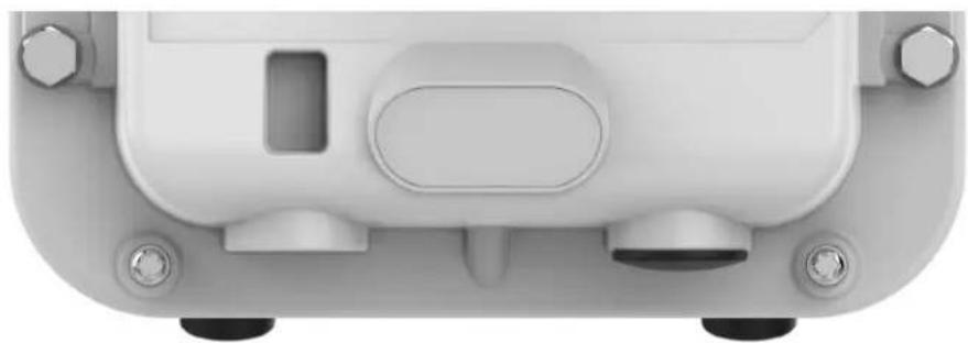
ODU interfaces
natural_image
Top-down view of a white electronic device casing with buttons and a rectangular panel (no text or symbols visible)SFP
Main
Ethernet
Table 1 ODU rear interfaces
| Port name | Connector | Interface | Description |
| Main Ethernet | RJ45 | POE input | 802.3at Power over Ethernet (POE). |
| 100/1000BASE-T Ethernet | Management and/or data. | ||
| SFP SFP Optical or Copper | Gigabit Ethernet | Management and/or data. | |
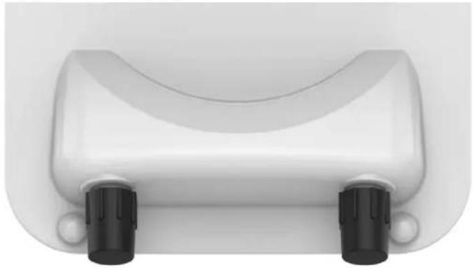
The front of the connectorized ODU provides N type female connectors for RF cable interfaces to antennas with horizontal (H) and vertical (V) polarization.
natural_image
Top-down view of a white plastic or cushion device with two black buttons at the bottom (no text or symbols visible)LED Reference
| RF3 |
| RF2 |
| RF1 |
| SFP |
| ETH |
| SYNC |
| PWR |
| LED Color | Status Indication |
| PWR | PWR LED is “Red” -- PTP 550 is connected to a power source |
| SYNC | SYNC LED is “Yellow” -- PTP 550 is connected to a sync source |
| ETH | ETH LED is “Red” -- PTP 550 has a 10BASE-T link |
| ETH | ETH LED is “Green” -- PTP 550 has a 100BASE-T link |
| ETH | ETH LED is “Orange” -- PTP 550 has a 1000BASE-T link |
| SFP | SFP LED is “Red” -- PTP 550 has a 10BASE-T link |
| SFP | SFP LED is “Green” -- PTP 550 has a 100BASE-T link |
| SFP | SFP LED is “Orange” -- PTP 550 has a 1000BASE-T link |
| RF 1-3 | RF 1, 2, & 3 indicate the RF signal strength |
Power Supply Unit (PSU) description
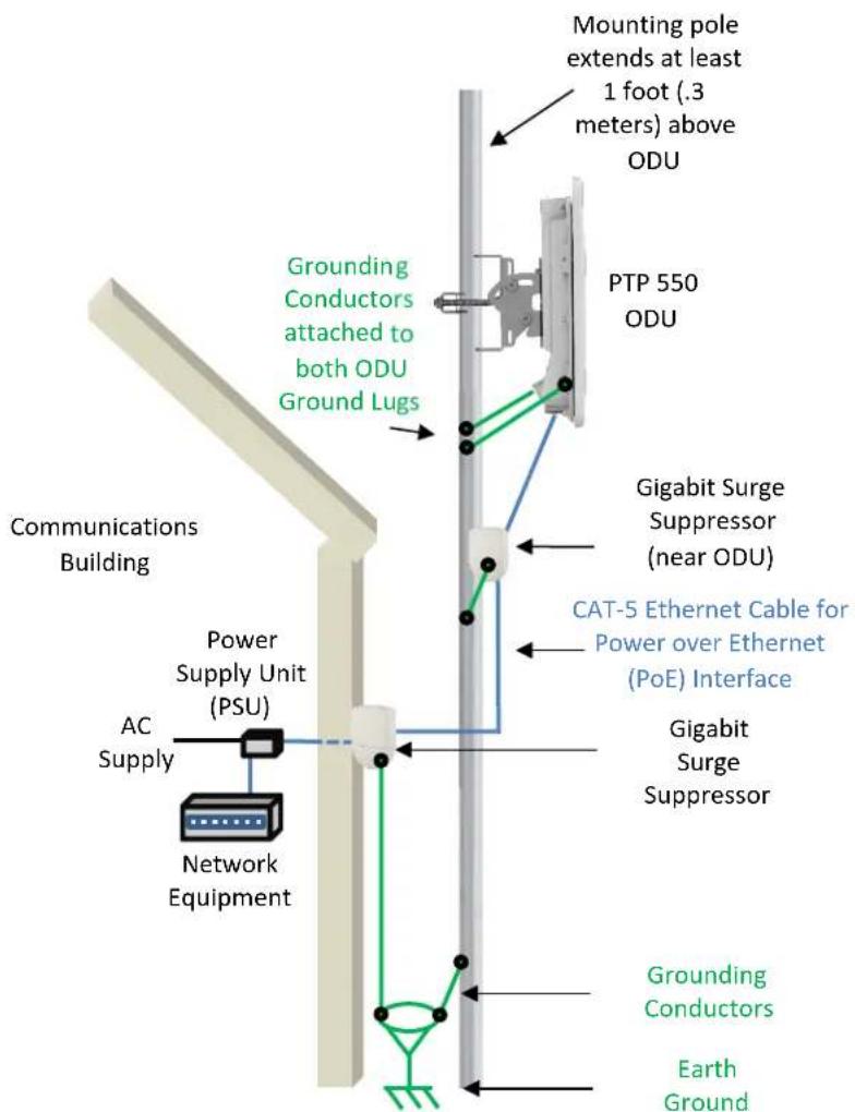
The PSU is an indoor unit that is connected to the ODU and network terminating equipment using Cat5e cable with RJ45 connectors. It is also plugged into an AC power supply so that it can inject Power over Ethernet (POE) into the ODU.

Warning Always use an appropriately rated and approved AC supply cord-set in accordance with the regulations of the country of use.

Attention The PSU ODU ports are designed to connect only to PTP 550 ODUs. Do not connect any other equipment, as damage may occur.
Do not connect the PIDU Plus PTP 300/500/600 Series to the PTP 550 ODU.
Order PSUs and (for AC power) line cords from Cambium Networks.
Table 2 Power supply component part numbers
| Cambium description Cambium part number | |
| PTP 550 AC Power Injector | N000000L034A |
| CABLE, UL POWER SUPPLY CORD SET, 720mm, US | N000900L031A |
| CABLE, UL POWER SUPPLY CORD SET, 720mm, EU | N000900L032A |
Typical bridge deployment
Configuration
Configuring the management PC
1 Select Properties for the Ethernet port. In Windows 7 this is found in Control Panel > Network and Internet > Network Connections > Local Area Connection.
2 Select Internet Protocol (TCP/IP):
3 Click Properties.
4 Enter an IP address that is valid for the 169.254.X.X network, avoiding 169.254.0.0 and 169.254.1.1. A good example is 169.254.1.3:
5 Enter a subnet mask of 255.255.0.0. Leave the default gateway blank.
Connecting to the PC and powering up
1 Check that the ODU ETH port is connected to the Ethernet + Power port of the power supply.
2 Connect the PC Ethernet port to the LAN port of the PSU using a standard (not crossed) Ethernet cable.
3 Apply mains or battery power to the PSU. The green Power LED should illuminate continuously.
4 Check that the ODU red Ethernet LED illuminates continuously.
5 Open a web browser and type: 169.254.1.1
When prompted, enter admin/admin to login to the GUI and complete the configuration.
Conforming to the limits
Ensure the link is configured to conform to local regulatory requirements by configuring the Country parameter (located in the web management interface at Configuration > Radio > General). When using connectorized ODUs with external antennas, also ensure that the antenna gain is configured correctly in the ODU (the Antenna Gain parameter is located in the web management interface at Configuration > Radio > Power Control).
Operation in the EU
Frequency Bands, Maximum Operating Power, Safe distance
In the EU, the 5 GHz PTP 550 products operate in the following frequency bands up to the maximum power shown:
| Operating Frequency Band | EU Standard | Maximum Power Limit (EIRP) | Permitted usage | 5 GHz units that support this frequency band |
| 5470 - 5725 MHz | EN 301 893 | 1 Watt / 30 dBm | Available for general usage within all EU nations | All PTP 550 |
| 5725 - 5875 MHz | EN 302 502 | 4 Watts / 36 dBm | Permitted in some EU nations, see notes 1 - 5 | All PTP 550 |
Note 1: Operation in the 5.8 GHz band is not permitted in the following European countries: AT, BG, CZ, CY, FR, HR, IT, LU, LV, NL, PL, TR. In other countries, government licenses may be required to allow operation, please check your national government website.
Note 2: The radio applies national frequency allocations, power and DFS settings for each country code.
Note 3: In the UK and Ireland, light licensing applies. Obtain a license from your government website.
Note 4: For Norway, use of the 5725-5795 MHz and 5815-5850 MHz frequency bands is authorized.
Note 5: 5725 - 5875 MHz operation is enabled by downloading and applying a license key from the Cambium web-site.
For PTP 550 products deployed in the EU, the minimum safe distance between the equipment and humans is 10 cm.
Restrictions & requirements for authorization for use
• This equipment is for outdoor use only.
- The PTP 550 products can be configured to operate in either licensed or unlicensed frequency bands subject to frequency planning within individual countries. Operators / End users must ensure that the equipment is installed and operated in accordance with the regulations applicable to the country of operation and obtain any necessary licenses or permits.
Simplified EU Declaration of Conformity
Hereby, the manufacturer Cambium Networks Ltd, declares that the radio equipment types PTP 550 Integrated 5 GHz / PTP 550 Connectorized 5 GHz are in compliance with Directive 2014/53/EU. The full text of the EU declaration of conformity is available at the following internet address: http://www.cambiumnetworks.com/eu_dofc
Waste Electrical and Electronic Equipment (WEEE) directive

Please do not dispose of Electronic and Electric Equipment or Electronic and Electric Accessories with your household waste. In some countries or regions, collection systems have been set up to handle waste of electrical and electronic equipment. In European Union countries, please contact your local equipment supplier representative or Cambium Networks Support Centre for information about the waste collection system in your country.
Online Resources

User Guide and Getting Started Guide: https://support.cambiumnetworks.com/guides
Support: https://www.cambiumnetworks.com/support/
Contact us: https://www.cambiumnetworks.com/support/contact-support/
Technical Training: https://learning.cambiumnetworks.com
natural_image
Top-down view of a white electronic device casing with buttons and a rectangular panel (no text or symbols visible)SFP Hlavní
Ethernet
natural_image
Top-down view of a white plastic or cushion device with two black buttons at the bottom (no text or symbols visible)Popis diod LED
Podpora: https://www.cambiumnetworks.com/support/
Kontaktujte nás: https://www.cambiumnetworks.com/support/contact-support/
Technicke školeni: https://learning.cambiumnetworks.com
natural_image
Top-down view of a white electronic device casing with buttons and a rectangular panel (no text or symbols visible)SFP Ethernet
natural_image
Top-down view of a white plastic or cushion device with two black buttons at the base (no text or symbols visible)Attention Always use an appropriately rated and approved AC supply cord-set in accordance with the regulations of the country of use.

Attention The PSU ODU ports are designed to connect only to PTP 550 ODUs. Do not connect any other equipment, as damage may occur. Do not connect the PIDU Plus PTP 300/500/600 Series to the PTP 550 ODU.
Order PSUs and (for AC power) line cords from Cambium Networks.
Table 5 Power supply component part numbers
| Cambium description | Cambium part number |
| PTP 550 AC Power Injector | N000000L034A |
| CABLE, UL POWER SUPPLY CORD SET, 720mm, US | N000900L031A |
| CABLE, UL POWER SUPPLY CORD SET, 720mm, EU | N000900L032A |
Conforming to the limits
Ensure the link is configured to conform to local regulatory requirements by configuring the Country parameter (located in the web management interface at Configuration > Radio > General). When using connectorized ODUs with external antennas, also ensure that the antenna gain is configured correctly in the ODU (the Antenna Gain parameter is located in the web management interface at Configuration > Radio > Power Control).
Assistance : https://www.cambiumnetworks.com/support/
Nous contacter : https://www.cambiumnetworks.com/support/contact-support/
Formation Technique: https://learning.cambiumnetworks.com
Connectorized units can operate with a selection of separately-purchased single and dual-polarity external antennas through 2 x N-type female connectors. The installer is responsible to operate the radio equipment and the accessories as intended and according to the description provided by the antenna manufacturer. The maximum antenna gain allowed for external antennas is 40 dBi.
natural_image
Top-down view of a white electronic device casing with buttons and a rectangular panel (no text or symbols visible)SFP Ethernet
natural_image
White plastic soap dispenser with black buttons at the bottom (no text or symbols visible)LED-Anzeigen

Power Supply Unit (PSU) description
The PSU is an indoor unit that is connected to the ODU and network terminating equipment using Cat5e cable with RJ45 connectors. It is also plugged into an AC power supply so that it can inject Power over Ethernet (POE) into the ODU.

Warnung Always use an appropriately rated and approved AC supply cord-set in accordance with the regulations of the country of use.

Beachtung The PSU ODU ports are designed to connect only to PTP 550 ODUs. Do not connect any other equipment, as damage may occur. Do not connect the PIDU Plus PTP 300/500/600 Series to the PTP 550 ODU.
Order PSUs and (for AC power) line cords from Cambium Networks.
Table 7 Power supply component part numbers
| Cambium description Cambium part number | |
| PTP 550 AC Power Injector | N000000L034A |
| CABLE, UL POWER SUPPLY CORD SET, 720mm, US | N000900L031A |
| CABLE, UL POWER SUPPLY CORD SET, 720mm, EU | N000900L032A |
Ensure the link is configured to conform to local regulatory requirements by configuring the Country parameter (located in the web management interface at Configuration > Radio > General). When using connectorized ODUs with external antennas, also ensure that the antenna gain is configured correctly in the ODU (the Antenna Gain parameter is located in the web management interface at Configuration > Radio > Power Control).
Betrieb in der EU
Support: https://www.cambiumnetworks.com/support/
Kontakt: https://www.cambiumnetworks.com/support/contact-support/
Technisches Training: https://learning.cambiumnetworks.com
Connectorized units can operate with a selection of separately-purchased single and dual-polarity external antennas through 2 x N-type female connectors. The installer is responsible to operate the radio equipment and the accessories as intended and according to the description provided by the antenna manufacturer. The maximum antenna gain allowed for external antennas is 40 dBi.
natural_image
Top-down view of a white electronic device casing with buttons and a rectangular panel (no text or symbols visible)SFP
Fö Ethernet
natural_image
Top-down view of a white plastic or cushion device with two black buttons at the bottom (no text or symbols visible)A ledek jelentése
The PSU is an indoor unit that is connected to the ODU and network terminating equipment using Cat5e cable with RJ45 connectors. It is also plugged into an AC power supply so that it can inject Power over Ethernet (POE) into the ODU.

Attention The PSU ODU ports are designed to connect only to PTP 550 ODUs. Do not connect any other equipment, as damage may occur. Do not connect the PIDU Plus PTP 300/500/600 Series to the PTP 550 ODU.
Order PSUs and (for AC power) line cords from Cambium Networks.
Conforming to the limits
Ensure the link is configured to conform to local regulatory requirements by configuring the Country parameter (located in the web management interface at Configuration > Radio > General). When using connectorized ODUs with external antennas, also ensure that the antenna gain is configured correctly in the ODU (the Antenna Gain parameter is located in the web management interface at Configuration > Radio > Power Control).
Connectorized units can operate with a selection of separately-purchased single and dual-polarity external antennas through 2 x N-type female connectors. The installer is responsible to operate the radio equipment and the accessories as intended and according to the description provided by the antenna manufacturer. The maximum antenna gain allowed for external antennas is 40 dBi.
natural_image
Top-down view of a white electronic device casing with buttons and a rectangular panel (no text or symbols visible)SFP Porta
natural_image
Top-down view of a white plastic or cushion device with two black buttons at the base (no text or symbols visible)Spie LED
Power Supply Unit (PSU) description
The PSU is an indoor unit that is connected to the ODU and network terminating equipment using Cat5e cable with RJ45 connectors. It is also plugged into an AC power supply so that it can inject Power over Ethernet (POE) into the ODU.

Attenzione The PSU ODU ports are designed to connect only to PTP 550 ODUs. Do not connect any other equipment, as damage may occur. Do not connect the PIDU Plus PTP 300/500/600 Series to the PTP 550 ODU.
Order PSUs and (for AC power) line cords from Cambium Networks.
Ensure the link is configured to conform to local regulatory requirements by configuring the Country parameter (located in the web management interface at Configuration > Radio > General). When using connectorized ODUs with external antennas, also ensure that the antenna gain is configured correctly in the ODU (the Antenna Gain parameter is located in the web management interface at Configuration > Radio > Power Control).
Connectorized units can operate with a selection of separately-purchased single and dual-polarity external antennas through 2 x N-type female connectors. The installer is responsible to operate the radio equipment and the accessories as intended and according to the description provided by the antenna manufacturer. The maximum antenna gain allowed for external antennas is 40 dBi.
natural_image
Top-down view of a white electronic device casing with buttons and a central button (no text or symbols visible)natural_image
Top-down view of a white plastic or cushion device with two black buttons at the bottom (no text or symbols visible)The PSU is an indoor unit that is connected to the ODU and network terminating equipment using Cat5e cable with RJ45 connectors. It is also plugged into an AC power supply so that it can inject Power over Ethernet (POE) into the ODU.

Order PSUs and (for AC power) line cords from Cambium Networks.
Table 11 Power supply component part numbers
| Cambium description Cambium part number | |
| PTP 550 AC Power Injector | N000000L034A |
| CABLE, UL POWER SUPPLY CORD SET, 720mm, US | N000900L031A |
| CABLE, UL POWER SUPPLY CORD SET, 720mm, EU | N000900L032A |
Ensure the link is configured to conform to local regulatory requirements by configuring the Country parameter (located in the web management interface at Configuration > Radio > General). When using connectorized ODUs with external antennas, also ensure that the antenna gain is configured correctly in the ODU (the Antenna Gain parameter is located in the web management interface at Configuration > Radio > Power Control).
Connectorized units can operate with a selection of separately-purchased single and dual-polarity external antennas through 2 x N-type female connectors. The installer is responsible to operate the radio equipment and the accessories as intended and according to the description provided by the antenna manufacturer. The maximum antenna gain allowed for external antennas is 40 dBi.
natural_image
Top-down view of a white electronic device casing with buttons and a rectangular panel (no text or symbols visible)SFP Ethernet
principal
Tabla 12 Interfaces posteriores de la ODU
natural_image
Top-down view of a white plastic or cushion device with two black buttons at the bottom (no text or symbols visible)Referencias de LED
Power Supply Unit (PSU) description
The PSU is an indoor unit that is connected to the ODU and network terminating equipment using Cat5e cable with RJ45 connectors. It is also plugged into an AC power supply so that it can inject Power over Ethernet (POE) into the ODU.

Warning Always use an appropriately rated and approved AC supply cord-set in accordance with the regulations of the country of use.

Attention The PSU ODU ports are designed to connect only to PTP 550 ODUs. Do not connect any other equipment, as damage may occur. Do not connect the PIDU Plus PTP 300/500/600 Series to the PTP 550 ODU.
Order PSUs and (for AC power) line cords from Cambium Networks.
Table 13 Power supply component part numbers
| Cambium description | Cambium part number |
| PTP 550 AC Power Injector | N000000L034A |
| CABLE, UL POWER SUPPLY CORD SET, 720mm, US | N000900L031A |
| CABLE, UL POWER SUPPLY CORD SET, 720mm, EU | N000900L032A |
Conforming to the limits
Ensure the link is configured to conform to local regulatory requirements by configuring the Country parameter (located in the web management interface at Configuration > Radio > General). When using connectorized ODUs with external antennas, also ensure that the antenna gain is configured correctly in the ODU (the Antenna Gain parameter is located in the web management interface at Configuration > Radio > Power Control).
Connectorized units can operate with a selection of separately-purchased single and dual-polarity external antennas through 2 x N-type female connectors. The installer is responsible to operate the radio equipment and the accessories as intended and according to the description provided by the antenna manufacturer. The maximum antenna gain allowed for external antennas is 40 dBi.
natural_image
Top-down view of a white electronic device casing with buttons and a central button (no text or symbols visible)SFP Ana Ethernet
natural_image
White plastic electronic device with two black buttons at the bottom (no text or symbols visible)Power Supply Unit (PSU) description
The PSU is an indoor unit that is connected to the ODU and network terminating equipment using Cat5e cable with RJ45 connectors. It is also plugged into an AC power supply so that it can inject Power over Ethernet (POE) into the ODU.

Warning Always use an appropriately rated and approved AC supply cord-set in accordance with the regulations of the country of use.

Attention The PSU ODU ports are designed to connect only to PTP 550 ODUs. Do not connect any other equipment, as damage may occur. Do not connect the PIDU Plus PTP 300/500/600 Series to the PTP 550 ODU.
Order PSUs and (for AC power) line cords from Cambium Networks.
Table 15 Power supply component part numbers
| Cambium description Cambium part number | |
| PTP 550 AC Power Injector | N000000L034A |
| CABLE, UL POWER SUPPLY CORD SET, 720mm, US | N000900L031A |
| CABLE, UL POWER SUPPLY CORD SET, 720mm, EU | N000900L032A |
Conforming to the limits
Ensure the link is configured to conform to local regulatory requirements by configuring the Country parameter (located in the web management interface at Configuration > Radio > General). When using connectorized ODUs with external antennas, also ensure that the antenna gain is configured correctly in the ODU (the Antenna Gain parameter is located in the web management interface at Configuration > Radio > Power Control).
AB'de Çalıştırma


- Cambium Networks™
- QUICK START GUIDE
- PTP 550 Series
- Accuracy
- Copyrights
- Restrictions
- License Agreements
- High Risk Materials
- Equipment manufacturer
- Contents
- English (UK, IE, NO) 5
- Czech (CZ)....12
- Intended use
- Installation & Operation
- Product Safety information
- Kit Contents
- Integrated ODU Kit Contents Connectorized ODU Kit Contents
- ODU interfaces
- Power Supply Unit (PSU) description
- Configuration
- Configuring the management PC
- Connecting to the PC and powering up
- Conforming to the limits
- Operation in the EU
- Frequency Bands, Maximum Operating Power, Safe distance
- Restrictions & requirements for authorization for use
- Simplified EU Declaration of Conformity
- Waste Electrical and Electronic Equipment (WEEE) directive
- Online Resources
- LED-Anzeigen
- Betrieb in der EU
- A ledek jelentése
- Spie LED
- AB'de Çalıştırma
Brand : Cambium Networks
Model : PTP 550e
Category : Telecommunication Equipment