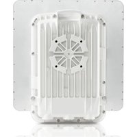
PTP 670 - Telecommunication Equipment Cambium Networks - Free user manual and instructions
Find the device manual for free PTP 670 Cambium Networks in PDF.


| Product type | Outdoor point-to-point (PTP) radio |
| Brand | Cambium Networks |
| Model | PTP 670 |
| Intended use | Data transmission over point-to-point microwave links, for fixed outdoor professional installations |
| Frequency bands | 5.47-5.60 GHz and 5.65-5.725 GHz (license-exempt EU bands) |
| Maximum transmit power (EIRP) | 1 watt (30 dBm) |
| Antenna types | Integrated (23 dBi) or external (parabolic, flat panel, sector, omnidirectional) |
| Power supply | AC power injector (N000065L001C) or enhanced AC+DC (C000065L002C) |
| Connectivity | Ethernet Cat.5e (PSU port), optional SFP and AUX ports |
| Lightning protection | Grounding kit and LPU (Lightning Protection Unit) mandatory |
| Minimum safety distance (RF) | 0 cm (according to EU standard for 5.4 GHz band) |
| Installation | Professional, on mast or tower, with tiltable mounts |
| Standards | Compliant with RED Directive 2014/53/EU, EN 301 893 |
| Safety | Mandatory grounding, do not work under voltage, respect RF distances |
| Maintenance and cleaning | Clean connectors with suitable products, check cable sealing |
| Spare parts and repairability | LPU kits, cables, connectors, and mounts available from Cambium Networks. Repair by a professional only. |
| Documentation | Quick start guide and user guide available at support.cambiumnetworks.com |
Frequently Asked Questions - PTP 670 Cambium Networks
User questions about PTP 670 Cambium Networks
0 question about this device. Answer the ones you know or ask your own.
Ask a new question about this device
Download the instructions for your Telecommunication Equipment in PDF format for free! Find your manual PTP 670 - Cambium Networks and take your electronic device back in hand. On this page are published all the documents necessary for the use of your device. PTP 670 by Cambium Networks.
USER MANUAL PTP 670 Cambium Networks
About this Quick Start Guide. 9
Intended use 9
Operation in the EU 9
Simplified EU Declaration of Conformity 11
Professional installation 11
User documentation. 11
Waste Electrical and Electronic Equipment (WEEE) 11
Safety 11
Equipment manufacturer 13
TYPICAL INSTALLATIONS 14
ODU VARIANTS AND MOUNTING BRACKET OPTIONS. 15
INSTALLING THE ODU AND TOP LPU 17
Attach ground cables to the ODU. 17
Mount the ODU on the mast. 17
Mount the top LPU. 20
Interconnect and ground the ODU and top LPU 20
Install external antennas for a Connectorized ODU 21
INSTALLING THE COPPER CAT5E ETHERNET INTERFACE 23
Install the ODU to top LPU drop cable. 23
Install the main drop cable. 25
Install the bottom LPU to PSU drop cable 27
Test resistance in the drop cable. 28
INSTALLING THE PSU 30
Instaing the AC Power Injector 30
Installing the AC+DC Enhanced Power Injector 30
CONFIGURING THE ODU FOR OPERATION IN THE EU 32
Generate a country-specific License Key 32
Configure the management PC 32
Connect the ODU to the PC and powering up. 32
Logging into the web interface 32
Update the License Key and configure the ODU. 33
CZECH (CS) 35
POZNÁMKY 36
INSTALACE VENKOVNI JEDNOTKY A HORNI PREPETOVE OCHRANY 44
English (UK, IE, NO)
Accuracy
While reasonable efforts have been made to assure the accuracy of this document, Cambium Networks assumes no liability resulting from any inaccuracies or omissions in this document, or from use of the information obtained herein. Cambium Networks reserves the right to make changes to any products described herein to improve reliability, function, or design, and reserves the right to revise this document and to make changes from time to time in content hereof with no obligation to notify any person of revisions or changes. Cambium Networks does not assume any liability arising out of the application or use of any product, software, or circuit described herein; neither does it convey license under its patent rights or the rights of others. It is possible that this publication may contain references to, or information about Cambium Networks products (machines and programs), programming, or services that are not announced in your country. Such references or information must not be construed to mean that Cambium Networks intends to announce such Cambium Networks products, programming, or services in your country.
Copyrights
This document, Cambium Networks products, and 3rd Party software products described in this document may include or describe copyrighted Cambium Networks and other 3rd Party supplied computer programs stored in semiconductor memories or other media. Laws in the United States and other countries preserve for Cambium Networks, its licensors, and other 3rd Party supplied software certain exclusive rights for copyrighted material, including the exclusive right to copy, reproduce in any form, distribute and make derivative works of the copyrighted material. Accordingly, any copyrighted material of Cambium Networks, its licensors, or the 3rd Party software supplied material contained in the Cambium Networks products described in this document may not be copied, reproduced, reverse engineered, distributed, merged or modified in any manner without the express written permission of Cambium Networks. Furthermore, the purchase of Cambium Networks products shall not be deemed to grant either directly or by implication, estoppel, or otherwise, any license under the copyrights, patents or patent applications of Cambium Networks or other 3rd Party supplied software, except for the normal non-exclusive, royalty free license to use that arises by operation of law in the sale of a product.
Restrictions
Software and documentation are copyrighted materials. Making unauthorized copies is prohibited by law. No part of the software or documentation may be reproduced, transmitted, transcribed, stored in a retrieval system, or translated into any language or computer language, in any form or by any means, without prior written permission of Cambium Networks.
License Agreements
The software described in this document is the property of Cambium Networks and its licensors. It is furnished by express license agreement only and may be used only in accordance with the terms of such an agreement.
High Risk Materials
Cambium and its supplier(s) specifically disclaim any express or implied warranty of fitness for any high risk activities or uses of its products including, but not limited to, the operation of nuclear facilities, aircraft navigation or aircraft communication systems, air traffic control, life support, or weapons systems ("High Risk Use"). Any High Risk is unauthorized, is made at your own risk and you shall be responsible for any and all losses, damage or claims arising out of any High Risk Use.
Notices
About this Quick Start Guide
This Quick Start Guide describes how to install the site equipment for PTP 670 Series links. Users of this guide must follow good practice for outdoor radio installations.
In more advanced configurations, there may be one or two additional Ethernet interfaces connected to the ODU: one to the SFP port (copper or optical) and one to the AUX port. For details of these configurations, refer to the PTP 670 Series User Guide.
This Quick Start Guide describes how to deploy PTP 670 in the following countries:
- Ireland
Norway
United Kingdom (UK)
PTP 670 Quick Start Guides are available for other EU member states. Please visit:
http://www.cambiumnetworks.com/guides
Intended use
The Cambium Networks PTP 670 series of radio products support data transmission over Point to Point (PTP) microwave links. This radio equipment is intended for professional applications for fixed outdoor installations only. These radios are available with an integrated antenna or as a unit for connection to an external antenna.
Operation in the EU
Frequency Bands, Maximum Operating Power, Safe Distance
The PTP 670 series products operate in the following frequency bands up to the maximum power shown:
| Operating Frequency Band | EU Standard | Maximum Power Limit (EIRP) | Permitted Usage | Minimum Safe Distance |
| 4940 - 4990 MHz | EN 302 625 | 8 watts/39 dBm | Norway: Broadband Disaster Relief | 0 cm |
| 5150 - 5250 MHz | EN 302 625 | 8 watts/39 dBm | Norway: Broadband Disaster Relief | 0 cm |
| 5470 - 5600 MHz | EN 301 893 | 1 watt/30 dBm | UK, Ireland, Norway: Unlicensed. | 0 cm |
| 5650 - 5725 MHz | ||||
| 5725 - 5875 MHz | EN 302 502 | 2 watts/33 dBm | Ireland: light licensing applies. Obtain a license from your government web-site. | 0 cm |
| 5725 - 5850 MHz | EN 302 502 | 4 watts/36 dBm | UK: light licensing applies. Obtain a license from your government web-site. | 0 cm |
| 5725 - 5795 MHz, 5815 - 5850 MHz | NCOM Reg. 628 EN 302 502 | 200 watts/53 dBm | Norway: Unlicensed 1.1 m |
Restrictions and requirements for authorization for use
This equipment is for outdoor use only.
The Cambium PTP 670 series of products can be configured to operate in either licensed or unlicensed frequency bands subject to frequency planning within individual countries. Operators and end users must ensure
that the equipment is installed and operated in accordance with the regulations applicable to the country of operation and obtain any necessary licenses or permits.
Antennas for connectorized units
PTP 670 Connectorised ODUs are designed to connect to a dual polarized antenna, using vertical and horizontal polarization. The radios have been tested for EU regulatory compliance using the antenna types listed below. The maximum gain of each antenna type is shown. Antennas of equivalent gain or lower and of the same antenna type may be used. Do not use an antenna with higher gain. To reduce potential radio interference to other users, the antenna type and its gain must be so chosen that the equivalent isotropic radiated power (EIRP) is not more than that necessary for successful communication.
| Antenna Type | Manufacturer's Antenna Gain (dBi) | ||
| 4.9 GHz Band, 5.1 GHz Band | 5.4 GHz Band | 5.8 GHz Band | |
| 6 foot (1.8 m) Parabolic Dish | 36.0 | Not Supported | 38.1 |
| 4 foot (1.2 m) Parabolic Dish | 32.6 | 34.9 | 35.3 |
| Flat Plate | 23.0 | 23.0 | 23.0 |
| Sectorised | 17.0 | 17.0 | 17.0 |
| Omnidirectional | 13.0 | 13.0 | 13.0 |
Recommended parabolic dish antennas
The following parabolic dish antennas are suitable for use with PTP 670 Connectorized ODUs, subject to the maximum antenna gain shown above.
| Cambium part number | Description |
| RDH4503B | 5.25-5.85GHz 2-ft (0.6m), 29.0 dBi, Dual-polarization, H-Pol & V-Pol, with fine adjustments |
| RDH4504B | 5.25-5.85GHz 3-ft (0.9m), 32.5 dBi, Dual-polarization, H-Pol & V-Pol |
| RDH4505B | 5.25-5.85GHz 4-ft (1.2m), 34.9 dBi, Dual-polarization, H-Pol & V-Pol |
| RDH4506B | 5.25-5.85GHz 6-ft (1.8m), 37.9 dBi, Dual-polarization, H-Pol & V-Pol |
| RDH4508B | 5.25-5.85GHz 2-ft (0.6m), 28.8 dBi, High Performance Dual-polarization |
| RDH4509B | 5.25-5.85GHz 3-ft (0.9m), 32.3 dBi, High Performance Dual-polarization |
| RDH4510B | 5.25-5.85GHz 4-ft (1.2m), 34.7 dBi, High Performance Dual-polarization |
| RDH4511B | 5.25-5.85GHz 6-ft (1.8m), 37.7 dBi, High Performance Dual-polarization |
Configuration of the ODU
Please observe the following important instructions during installation. This will set the equipment in compliance with national regulatory regulations.
- Ensure that the ODU has the latest firmware version installed. The firmware is available from the Cambium Support Centre web site, see link below.
- During equipment set-up, verify that the ODU is the EU regional variant. Use the Cambium Support Center to generate a country-specific License Key for the country where the product is being operated. Install the License Key in the ODU. The License Key will unlock additional regulatory bands that are allowed in the country of operation.
- For connectorized units, enter the antenna gain and cable loss into the Antenna Gain and Cable Loss attributes on the System Configuration page of the web-based interface.
Simplified EU Declaration of Conformity
Hereby, the manufacturer Cambium Networks Ltd, declares that the radio equipment types 5 GHz PTP 670 Connectorised ODU and 5 GHz PTP 670 Integrated ODU are in compliance with Directive 2014/53/EU. The full text of the EU declaration of conformity is available at:
http://www.cambiumnetworks.com/support/compliance/
Professional installation
Installation and operation of this product is complex. Please follow the instructions in this leaflet. Ensure that operation complies with the regulations of the country where the product is installed. Ensure that installers have the appropriate skills, knowledge and experience to perform the installation task including:
- Familiarity with current applicable national regulations including radio regulations, electrical installation regulations, surge protection regulations and 'working at heights' regulations;
Installation in accordance with Cambium Networks instructions; - Confirming that the equipment settings are compliant with national or regional regulations.
User documentation
For full PTP 670 installation planning instructions and a list of components, download the PTP 670 Series User Guide from:
http://support.cambiumnetworks.com/files/ptp670
Waste Electrical and Electronic Equipment (WEEE)

Please do not dispose of Electronic and Electric Equipment or Electronic and Electric Accessories with your household waste. In some countries or regions, collection systems have been set up to handle waste of electrical and electronic equipment. In European Union countries, please contact your local equipment supplier representative or Cambium Networks Support Centre for information about the waste collection system in your country.
For instructions on waste disposal of used products, refer to:
http://www.cambiumnetworks.com/support/wee-compliance
Safety

Warning To prevent loss of life or physical injury, observe the safety guidelines below. In no event shall Cambium Networks be liable for any injury or damage caused during the installation of the Cambium PTP 670. Ensure that only qualified personnel install a PTP 670 link.
Power lines
Exercise extreme care when working near power lines.
Working at heights
Exercise extreme care when working at heights.
PSU
Always use the AC Power Injector or AC+DC Enhanced Power Injector to power the ODU. Failure to use a Cambium supplied PSU could result in equipment damage and will invalidate the safety certification and may cause a safety hazard.
Grounding and protective earth
The Outdoor Unit (ODU) must be properly grounded to protect against lightning. It is the user's responsibility to install the equipment in accordance with national regulations. In the USA follow the requirements of the National Electrical code NFPA 70-2005 and 780-2004 Installation of Lightning Protection Systems. In Canada, follow Section 54 of the Canadian Electrical Code. These codes describe correct installation procedures for grounding the outdoor unit, mast, lead in wire and discharge unit, size of grounding conductors and connection requirements for grounding electrodes. Other regulations may apply in different countries and therefore it is recommended that installation of the outdoor unit be contracted to a professional installer.
DC supply
To power the ODU from a DC supply, use the AC+DC enhanced power injector (PSU) (Cambium part number C000065L002C). Ensure that the DC power supply meets the requirements specified in the PTP 670 Series User Guide.
Powering down before servicing
Before servicing PTP 670 equipment, always switch off the power supply and unplug it from the PSU. Do not disconnect the RJ45 drop cable connectors from the ODU while the PSU is connected to the power supply. Always remove the AC or DC input power from the PSU.
Primary disconnect device
The main power supply is the primary disconnect device. The AC-DC enhanced power injector is fused on the DC input. Some installations will also require an additional circuit breaker or isolation switch to be fitted in the DC supply.
External cables
Safety may be compromised if outdoor rated cables are not used for connections that will be exposed to the outdoor environment. For outdoor copper Cat5e Ethernet interfaces, always use Cat5e cable that is gel-filled and shielded with copper-plated steel. Alternative types of drop cable are not supported by Cambium Networks for use with PTP 670.
Always use a qualified electrician to install AC cabling.
Drop cable tester
A drop cable tester must NEVER be used at the ODU end connected to the power supply from the PSU. It must only be used at the bottom of the mast with a multimeter. This is because the PSU voltage exceeds the limit allowed in some countries for safe handling in wet conditions and therefore may create a safety hazard.
RF exposure near the antenna
Strong radio frequency (RF) fields will be present close to the antenna when the transmitter is on. Always turn off the power to the ODU before undertaking maintenance activities in front of the antenna.
Minimum separation distances
Ensure that personnel are not exposed to unsafe levels of RF energy. The units start to radiate RF energy as soon as they are powered up. Never work in front of the antenna when the ODU is powered. Install the ODUs so as to provide and maintain the minimum separation distances from all persons.
Grounding and lightning protection requirements
Ensure that the installation meets the requirements defined in the PTP 670 Series User Guide.
Grounding cable installation methods
To provide effective protection against lightning induced surges, observe these requirements:
Grounding conductor runs must be as short, straight and smooth as possible, with bends and curves kept to a minimum.
- Grounding cables must not be installed with drip loops.
All bends must have a minimum radius of 203 mm (8 in) and a minimum angle of 90^ . A diagonal run is preferable to a bend, even though it does not follow the contour or run parallel to the supporting structure.
- All bends, curves and connections must be routed towards the grounding electrode system, ground rod, or ground bar.
Grounding conductors must be securely fastened.
- Braided grounding conductors must not be used.
Approved bonding techniques must be used for the connection of dissimilar metals.
Siting ODUs and antennas
ODUs and external antennas are not designed to survive direct lightning strike. For this reason they must be installed in Zone B as defined in PTP 670 Series User Guide. Mounting in Zone A may put equipment, structures and life at risk.
Wind survival speeds
Ensure that the ODU and the structure to which it is mounted can withstand the maximum wind speeds at a proposed site.
Surface temperature
The ODU enclosure may be hot to the touch when in operation.
Equipment manufacturer
Cambium Networks Ltd, Unit B2 Linhay Business Park, Eastern Road, Ashburton, Devon, TQ13 7UP, United Kingdom.
Typical installations
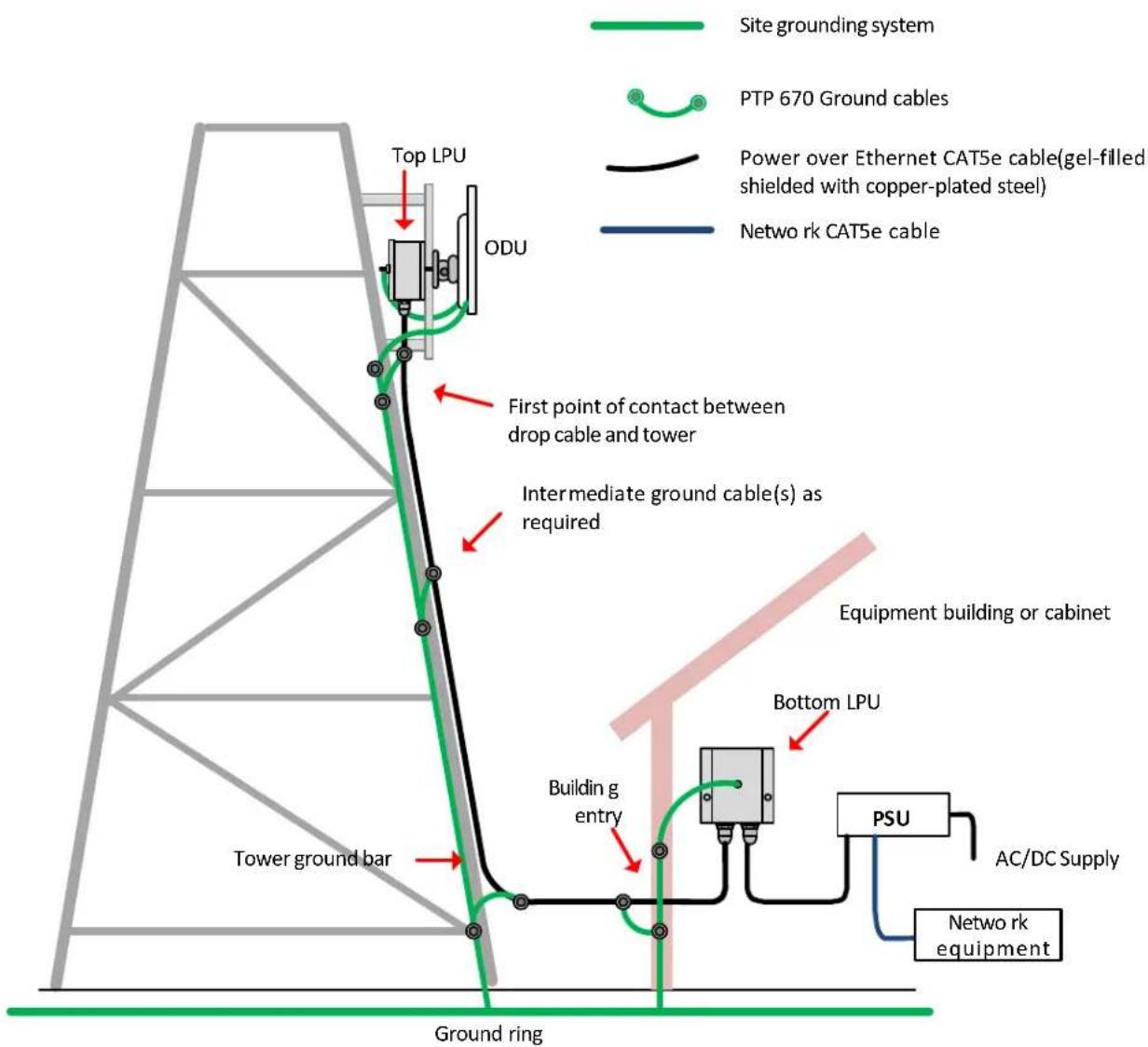
A PTP 670 site typically consists of a high supporting structure such as a mast, tower or building for the outdoor equipment (ODU and optional external antenna); and an equipment building or moisture-proof enclosure for the indoor equipment (PSU), as shown here in a typical mast or tower installation:

Note These instructions assume that LPUs are being installed from the LPU and grounding kit (Cambium part number C000065L007A). If the installation does not require LPUs, adapt these instructions as appropriate.
If LPUs are being installed, only use the five black-capped EMC cable glands supplied in the LPU and grounding kit. The silver-capped cable glands supplied in the ODU kits must only be used in PTP 670 installations which do not require LPUs.
ODU variants and mounting bracket options
ODU variants
The PTP 670 ODU is supplied in two platform variants.
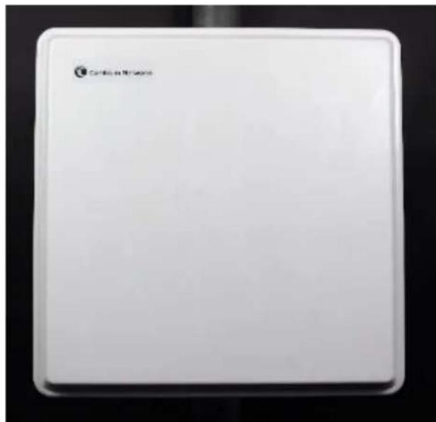
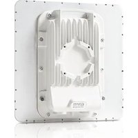
The PTP 670 Integrated ODU is attached to a 23 dBi flat plate antenna and is intended for medium to long-range difficult links and traditional backhaul requirements where high capacity and high link budget are required. The integrated antenna offers a convenient and easily-deployed solution where the additional gain of external antennas is not needed.
Integrated ODU (4.8 to 5.9 GHz)
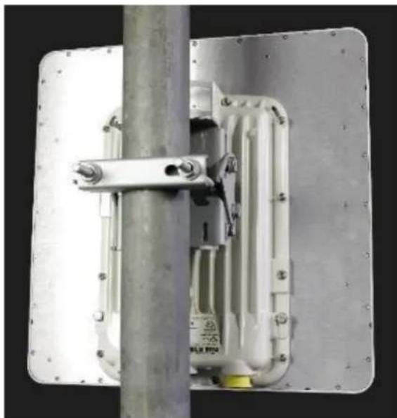
Integrated ODU (4.9 to 6.05 GHz)
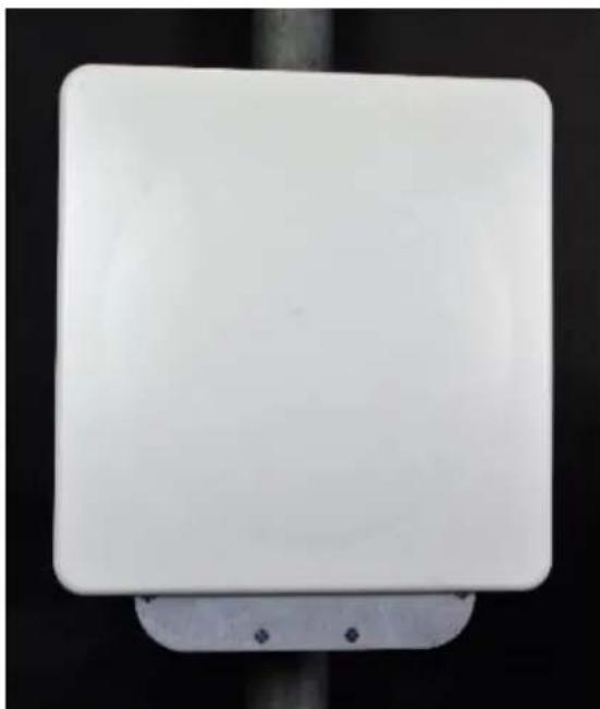
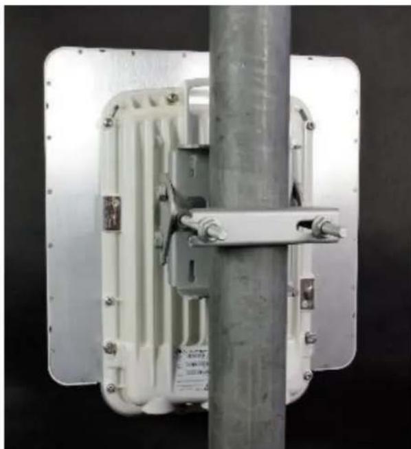
The PTP 670 Connectorized ODU is intended to work with separately mounted external antennas. External antennas generally have higher gains than the integrated antennas, allowing the PTP 670 to cope with more difficult radio conditions.
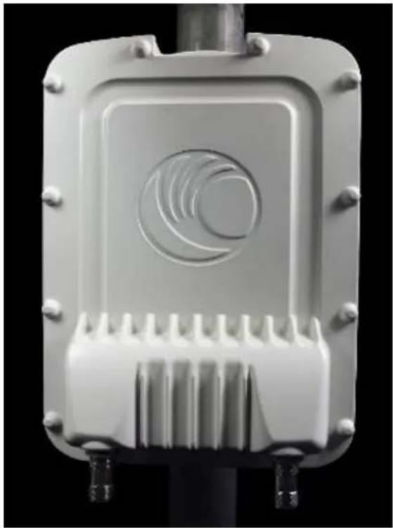
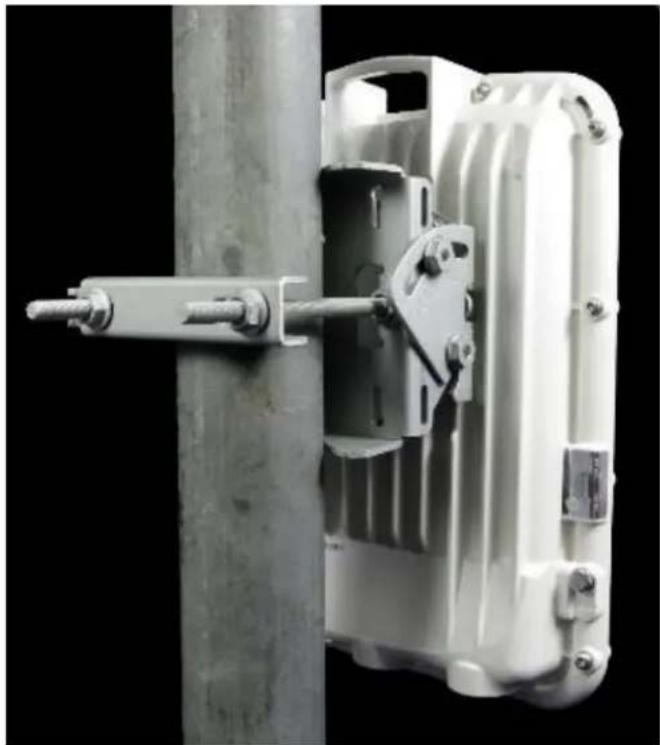
Mounting bracket options
The PTP 670 series supports three mounting bracket options. Select the optimum mounting bracket arrangement based on the pole diameter and the ODU variant:
| Bracket | Pole diameter | ODU variants | Bracket part number |
| Tilt Bracket Assembly 40 mm to 77 mm (1.6 inches to 3.0 inches) | PTP 670 Integrated PTP 670 Connectorized | N000045L002A | |
| Tilt Bracket Assembly with compression straps | 90 mm to 230 mm (3.6 inches to 9.0 inches) | PTP 670 Integrated PTP 670 Connectorized | N000045L002A + third-party band clamps |
| Mounting Bracket (Integrated) | 40 mm to 82 mm (1.6 inches to 3.2 inches) | PTP 670 Integrated N000065L031A | |


Note The Tilt Bracket Assembly is included as part of the PTP 670 Integrated and Connectorized Kits. If required, order the Mounting Bracket (Integrated) separately.
Note The Tilt Bracket Assembly allows for elevation angle adjustment for the Integrated ODU between -17^ and +26^ . The Mounting Bracket (Integrated) allows for elevation angle adjustment between -26^ and +41^ .
Installing the ODU and top LPU
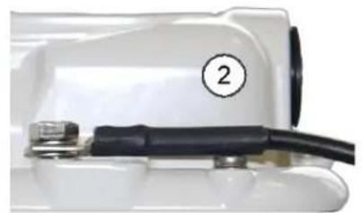
Attach ground cables to the ODU
1 Fasten one ground cable to each ODU grounding point using the M6 (small) lugs: one is for the top LPU (M6 lug at other end) and the other is for the tower or building (M10 lug at other end). It does not matter which cable goes on which ODU grounding point.
2 Tighten both ODU grounding bolts to a torque of 5.0 Nm (3.7 lb ft).

Mount the ODU on the mast
Select the most appropriate bracket mounting arrangement from the options listed in Mounting bracket options on page 16. Refer to individual procedures below for each of the options:
Tilt Bracket Assembly on page 17
Tilt Bracket Assembly with band clamps on page 18
- Mounting bracket (Integrated) on page 19
The mounting procedures can be adapted to attach the ODU to a suitable horizontal pole, but the adjustment of azimuth angle is necessarily limited compared with an installation on a vertical pole.
Tilt Bracket Assembly
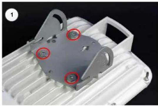
Fix the mounting plate of the Tilt Bracket to the back of the ODU using four of the short bolts, ensuring that the arrow in the plate points towards the top of the ODU. Tighten the four bolts to a torque setting of 5.0 Nm (3.7 lb ft) using a 13 mm spanner or socket.
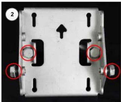
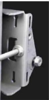
2 Fit the two long bolts through the bracket body so that the bolt heads engage in the slots as shown. Fit two of the short bolts into the side of the bracket body but do not tighten.
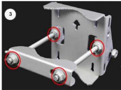
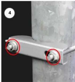
3 Thread two of the nuts to the long bolts and tighten against the bracket body using a 13 mm spanner. Fit the bracket strap and thread the remaining nuts onto the long bolts.
Fix the assembled bracket body to the pole, adjust the azimuth angle, and tighten the nuts to a torque setting of 10.0 Nm (7.4 lb ft) using a 13 mm spanner, ensuring that the arrow in the body is pointing upwards.
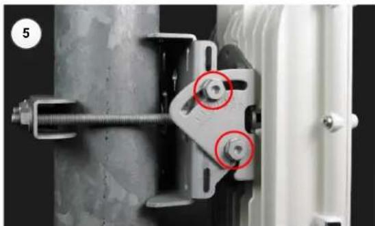
5 Hoist the ODU to the mounting position. Fit the mounting plate to the bracket body by positioning the open-ended slots over the short bolts. Insert the remaining short bolts through the longer curved slots into the threaded holes in the bracket body. Adjust the elevation angle, and tighten the bolts to a torque setting of 8.0 Nm (5.9 lb ft) using a 13 mm spanner or socket.
Tilt Bracket Assembly with band clamps
1 Follow Step 1 for the Tilt Bracket Assembly procedure above.
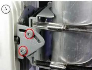
2 Feed the band clamps (not supplied by Cambium) through the slots in the bracket body. Secure the bracket body to the pole using band clamps, ensuring that the arrow in the body is pointing upwards. Adjust the azimuth angle, and tighten the band clamps to a torque setting of 6.0Nm (4.5 lb ft).
3 Hoist the ODU to the mounting position. Fix the mounting plate to the bracket body with four of the short bolts, using a 13mm spanner or socket. Adjust the elevation angle, and tighten the bolts to a torque setting of 8.0 Nm (5.9 lb ft).

Mounting bracket (Integrated)
Fix the mounting plate to the back of the ODU using the four bolts, and spring and plain washers provided. Ensure that the spring washer is between the bolt head and the plain washer. Tighten the bolts to a torque setting of 5.0 Nm (3.7 lb ft).
2 Attach the bracket body to the mounting plate using the M8 bolt, spring and plain washers. Ensure that the spring washer is between the bolt head and the plain washer
3 Hoist the ODU to the mounting position.
4 Attach the bracket body to the pole using the bracket clamp, M8 bolts, and spring and plain washers. Ensure that the spring washer is between the bolt head and the plain washer. For back-to-back mounting, use the LPU in place of the clamp.
5 Adjust the elevation and azimuth to achieve visual alignment. Tighten all three bracket bolts to a torque of 8.0 Nm (6.0 lb ft).
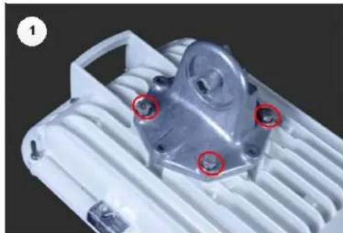
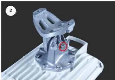
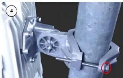
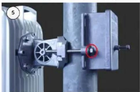
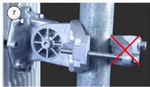

Attention Do not reverse the bracket clamp, as shown in 7 above as this arrangement may lead to failure of the assembly. Do not over-tighten the bolts as this may lead to failure of the assembly.
Mount the top LPU
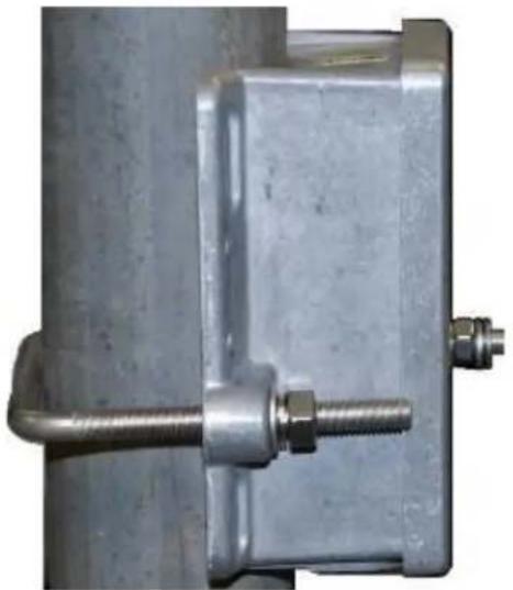
For separate LPU mounting, use the U bolt bracket from the LPU kit to mount the top LPU on the pole below the ODU. Tighten to a torque setting of 7.0 Nm (5.2 lb ft):
Interconnect and ground the ODU and top LPU
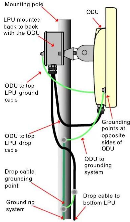
Option 1: back-to-back
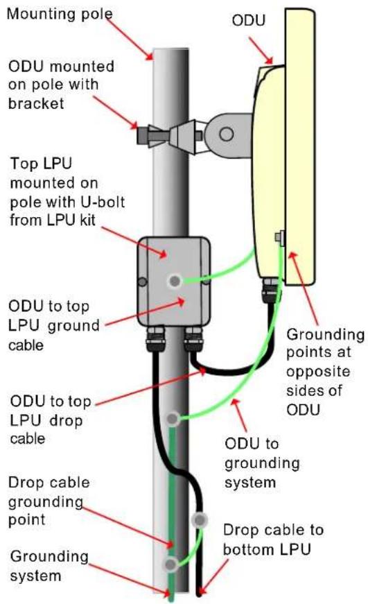
Option 2: separate

Attention Do not attach grounding cables to the ODU mounting bracket bolts, as this arrangement will not provide full protection.
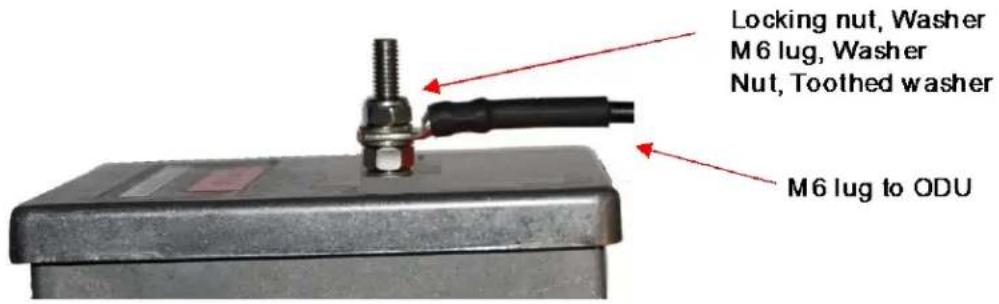
1 Fasten the ODU grounding cable to the top LPU using the M6 (small) lug. Tighten both nuts to a torque of 5 Nm (3.7 lb ft):
2 Select a tower or building grounding point within 0.3 meters (1 ft) of the ODU bracket. Remove paint from the surface and apply anti-oxidant compound. Fasten the ODU grounding cable to this point using the M10 (large) lug.
3 If local regulations mandate the independent grounding of all devices, add a third ground cable to connect the top LPU directly to the grounding system.
Install external antennas for a Connectorized ODU
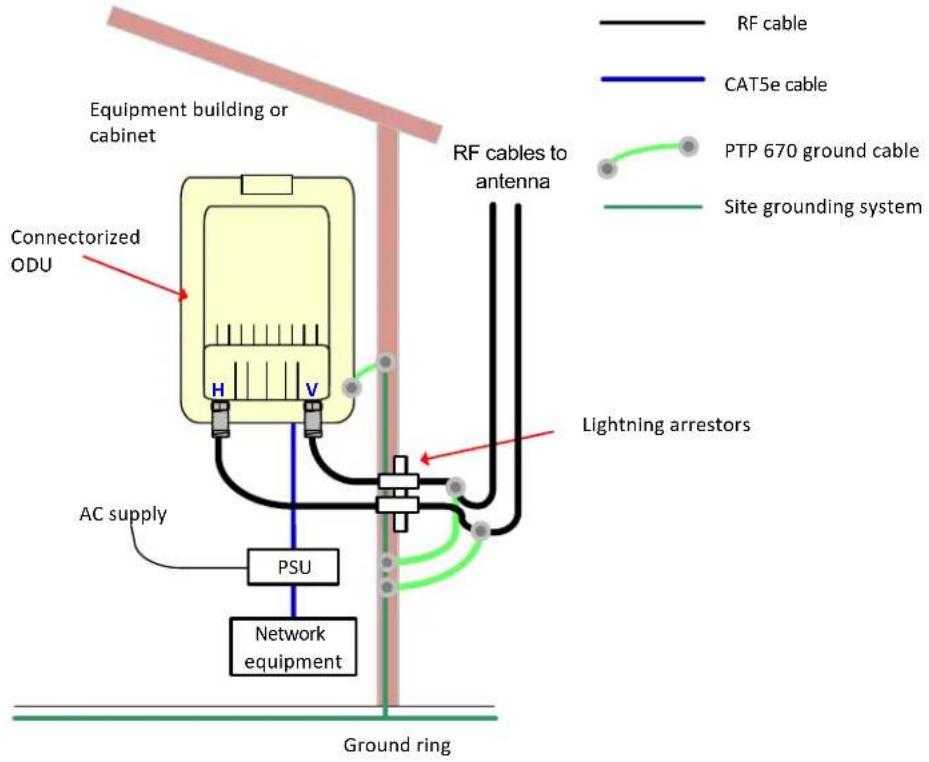
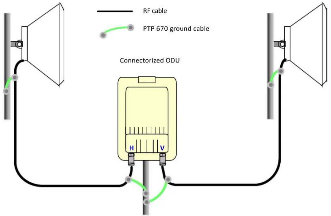
1 Mount the antenna(s) according to manufacturer's instructions. When using separate antennas to achieve spatial diversity, mount one with Horizontal polarization and the other with Vertical polarization.
2 Connect the ODU V and H interfaces to the antenna(s) with RF cable of type CNT 400 (Cambium part numbers 30010194001 and 30010195001) and N type connectors (Cambium part number 09010091001). Tighten the N type connectors to a torque setting of 1.7 Nm (1.3 lb ft) using 24 mm (0.9 in) wrench/spanner.
3 If the ODU is mounted indoors, install lightning arrestors at the building entry point:
4 Form drip loops near the lower ends of the antenna cables. These ensure that water is not channeled towards the connectors.
5 If the ODU is mounted outdoors, weatherproof the N type connectors (when antenna alignment is complete) using PVC tape and self-amalgamating rubber tape.
6 Weatherproof the antenna connectors in the same way (unless the antenna manufacturer specifies a different method).
7 Ground the antenna cables to the supporting structure within 0.3 meters (1 foot) of the ODU and antennas using the Cambium grounding kit (part number 01010419001):
Fix the antenna cables to the supporting structure using site approved methods. Ensure that no undue strain is placed on the ODU or antenna connectors. Ensure that the cables do not flap in the wind, as flapping cables are prone to damage and induce unwanted vibrations in the supporting structure.
Installing the copper Cat5e Ethernet interface
To install the copper Cat5e Ethernet interface, use the following procedures:
Install the ODU to top LPU drop cable on page 23
Install the main drop cable on page 25
Install the bottom LPU to PSU drop cable on page 27
Test resistance in the drop cable on page 28

Attention To avoid damage to the installation, do not connect or disconnect the drop cable when power is applied to the PSU or network terminating equipment.

Attention Do not connect the SFP or Aux drop cables to the PSU, as this may damage equipment.

Attention Always use Cat5e cable that is gel-filled and shielded with copper plated steel. Alternative types of Cat5e cable are not supported by Cambium Networks. Cambium Networks supply this cable (Cambium part numbers WB3175 and WB3176), RJ45 connectors (Cambium part number WB3177) and a crimp tool (Cambium part number WB3211). The LPU and grounding kit contains a 0.6 meters (2 foot) length of this cable.
Install the ODU to top LPU drop cable
Fit glands to the ODU to top LPU drop cable
Fit EMC strain relief cable glands (with black caps) to both ends of the 0.6 meters (2 foot) length of pre-terminated cable. These parts are supplied in the LPU and grounding kit.
1 Disassemble the gland and thread each part onto the cable (the rubber bung is split). Assemble the spring clip and the rubber bung:
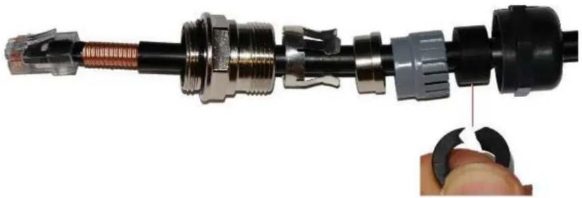
2 Fit the parts into the body and lightly screw on the gland nut using 24mm (0.9 in) wrench/spanner (do not tighten it):
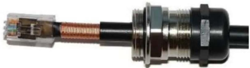
Connect the drop cable to the ODU (PSU port) and LPU
1 (a) Plug the RJ45 connector into the socket in the unit, ensuring that it snaps home. (b) Fit the gland body to the RJ45 port and tighten it to a torque of 5.5 Nm (4.1 lb ft):
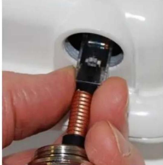
(a)
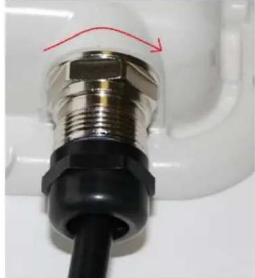
(b)
2 (a) Fit the gland nut and tighten until the rubber seal closes on the cable. (b) Do not over-tighten the gland nut, as there is a risk of damage to its internal components:
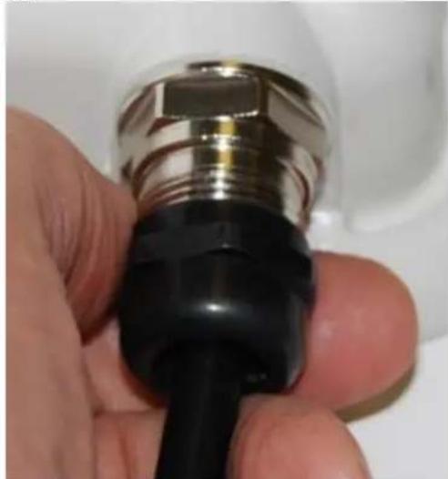
(a)
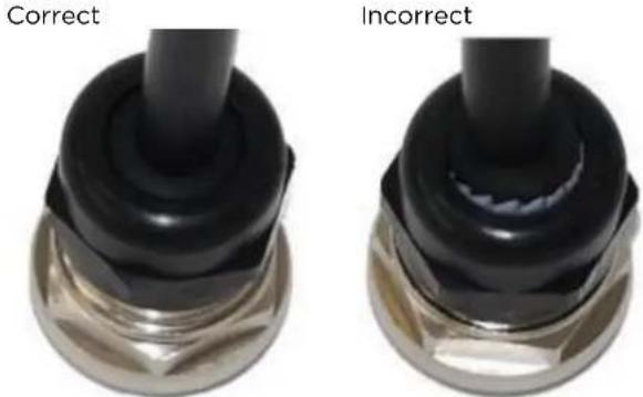
(b)
Disconnect the drop cable from the LPU or ODU
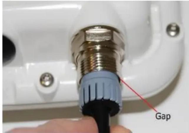
Use this procedure if it is necessary to remove an EMC strain relief cable gland and RJ45 connector from the ODU (as illustrated) or LPU.
1 (a) Remove the gland nut. Wiggle the drop cable to release the tension of the gland body. When the tension in the gland body is released, a gap opens at the point show. Unscrew the gland body.
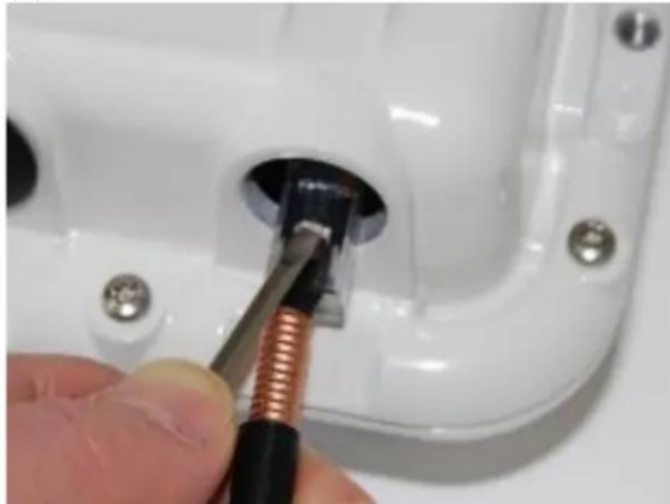
(b) Use a small screwdriver to press the RJ45 locking tab, then remove the RJ45 connector.
(a)
(b)
Install the main drop cable

Warning The metal screen of the drop cable is very sharp and may cause personal injury.
- ALWAYS wear cut-resistant gloves (check the label to ensure they are cut resistant).
- ALWAYS wear protective eyewear.
- ALWAYS use a rotary blade tool to strip the cable (DO NOT use a bladed knife).

Warning Failure to obey the following precautions may result in injury or death:
- Use the proper hoisting grip for the cable being installed. If the wrong hoisting grip is used, slippage or insufficient gripping strength will result.
- Do not reuse hoisting grips. Used grips may have lost elasticity, stretched, or become weakened. Reusing a grip can cause the cable to slip, break, or fall.
The minimum requirement is one hoisting grip for each 60m (197 ft) of cable.
Cut to length and fit hoisting grips
1 Cut the main drop cable to length from the top LPU to the bottom LPU.
2 Slide one or more hoisting grips onto the top end of the drop cable.
3 Secure the hoisting grip to the cable using a special tool, as recommended by the manufacturer.
Terminate with RJ45 connectors and glands

Attention Check that the crimp tool matches the RJ45 connector, otherwise the cable or connector may be damaged.
1 Thread the cable gland (with black cap) onto the main drop cable.
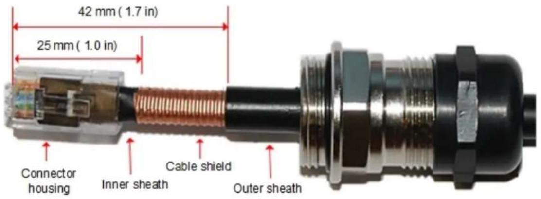
2 Strip the cable outer sheath and fit the RJ45 connector load bar.
3 Fit the RJ45 connector housing as shown. To ensure there is effective strain relief, locate the cable inner sheath under the connector housing tang. Do not tighten the gland nut:
Hoist and fix the main drop cable

Warning Failure to obey the following precautions may result in injury or death:
- Use the hoisting grip to hoist one cable only. Attempting to hoist more than one cable may cause the hoisting grip to break or the cables to fall.
- Do not use the hoisting grip for lowering cable unless the clamp is securely in place.
- Maintain tension on the hoisting grip during hoisting. Loss of tension can cause dangerous movement of the cable and result in injury or death to personnel.
- Do not release tension on the grip until after the grip handle has been fastened to the supporting structure.
- Do not apply any strain to the RJ45 connectors.

Attention Do not lay the drop cable alongside a lightning air terminal.
1 Hoist the top end of the main drop cable up to the top LPU, following the hoist manufacturer's instructions. When the cable is in position, fasten the grip handle to the supporting structure and remove the hoist line.
2 Connect the main drop cable to the top LPU by following the procedure Connect the drop cable to the ODU (PSU port) and LPU on page 16.
3 Run the main drop cable to the site of the bottom LPU.
4 Attach the main drop cable to the supporting structure using site approved methods.
Ground the main drop cable
At all required grounding points, connect the screen of the main drop cable to the metal of the supporting structure using the cable grounding kit (Cambium part number 01010419001).
Install the bottom LPU to PSU drop cable
Install the bottom LPU
Install the bottom LPU, ground it, and connect it to the main drop cable.
1 Select a mounting point for the bottom LPU within 0.6 meters (2 foot) of the building entry point. Mount the LPU vertically with cable glands facing downwards.
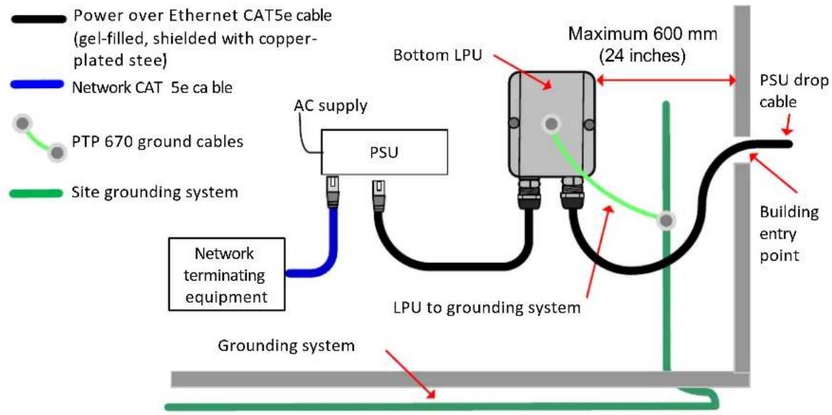
2 Connect the main drop cable to the bottom LPU by following the procedure Connect the drop cable to the ODU (PSU port) and LPU on page 24.
3 Fasten one ground cable to the bottom LPU using the M6 (small) lug. Tighten both nuts to a torque of 5 Nm (3.7 lb ft):
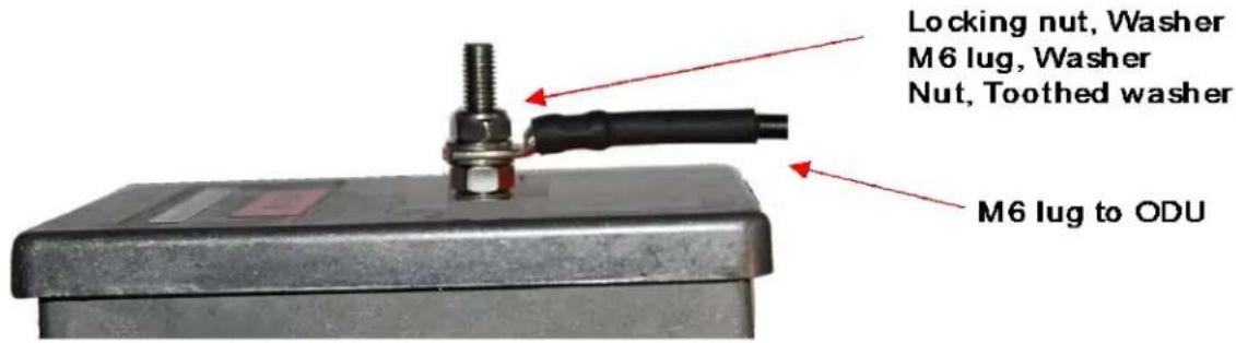
4 Select a building grounding point near the LPU bracket. Remove paint from the surface and apply antioxidant compound. Fasten the LPU ground cable using the M10 (large) lug.
Install the LPU to PSU drop cable
Use this procedure to terminate the bottom LPU to PSU drop cable with RJ45 connectors at both ends, and with a cable gland at the LPU end.

Warning The metal screen of the drop cable is very sharp and may cause personal injury.
ALWAYS wear cut-resistant gloves (check the label to ensure they are cut resistant).
- ALWAYS wear protective eyewear.
- ALWAYS use a rotary blade tool to strip the cable, not a bladed knife.

Attention Check that the crimp tool matches the RJ45 connector, otherwise the cable or connector may be damaged.
1 Cut the drop cable to the length required from bottom LPU to PSU.
2 At the LPU end only:
- Fit one cable gland and one RJ45 connector by following the procedure Terminate with RJ45 connectors and glands on page 26.
- Connect this cable and gland to the bottom LPU by following the procedure Connect the drop cable to the ODU (PSU port) and LPU on page 24.
3 At the PSU end only: Do not fit a cable gland. Strip the cable outer sheath and fit the RJ45 connector load bar. Fit the RJ45 connector housing. To ensure there is effective strain relief, locate the cable inner sheath under the connector housing tang:

Test resistance in the drop cable
Connect the bottom end of the copper Cat5e drop cable to a suitable drop cable tester and test that the resistances between pins are within the correct limits, as specified in the table below. If any of the tests fail, examine the drop cable for wiring faults.
| Measure the resistance between... | Enter measured resistance | To pass test, resistance must be... | Circle “Pass” or “Fail” | Additional tests and notes |
| Pins 1 and 2 Ohms <20 Ohms | Pass | |||
| (60 Ohms) (*1) | Fail | |||
| Pins 3 and 6 | Ohms | <20 Ohms | Pass | Resistances must be within 10% of each other (*2). Circle “Pass” or “Fail”: |
| (60 Ohms) (*1) | Fail | |||
| Pins 4 and 5 Ohms | <20 Ohms | Pass | Pass | |
| (60 Ohms) (*1) | Fail | Fail | ||
| Pins 7 and 8 Ohms <20 Ohms | Pass | |||
| (60 Ohms) (*1) | Fail | |||
| Pin 1 and screen (ODU ground) | K Ohms >100K Ohms Pass | Fail | These limits apply regardless of cable length. | |
| Pin 8 and screen (ODU ground) | K Ohms >100K Ohms Pass | Fail | ||
(^1) A resistance of 20 Ohms is the maximum allowed when the cable is carrying Ethernet.
A resistance of 60 Ohms is the maximum allowed when the cable is carrying only power to the ODU (when Ethernet is carried by one of the other ODU interfaces).
(^2) Ensure that these resistances are within 10% of each other by multiplying the lowest resistance by 1.1 - if any of the other resistances are greater than this, the test has failed.
Installing the PSU
Install one of the following types of PSU (as specified in the installation plan):
AC Power Injector (Cambium part number N000065L001C).
- AC+DC Enhanced Power Injector (Cambium part number C000065L002C).

Attention As the PSU is not waterproof, locate it away from sources of moisture, either in the equipment building or in a ventilated moisture-proof enclosure. Do not locate the PSU in a position where it may exceed its temperature rating.

Attention Do not plug any device other than a PTP 650, PTP 670 or PTP 700 ODU into the ODU port of the PSU. Other devices may be damaged due to the non-standard techniques employed to inject DC power into the Ethernet connection between the PSU and the ODU. Do not plug any device other than a Cambium PTP 670 PSU into the PSU port of the ODU. Plugging any other device into the PSU port of the ODU may damage the ODU and device.
Installing the AC Power Injector
Follow this procedure to install the AC Power Injector (Cambium part number N000065L001C):
1 Form a drip loop on the PSU end of the LPU to PSU drop cable. The drip loop ensures that any moisture that runs down the cable cannot enter the PSU.
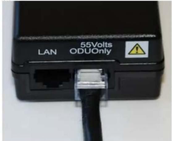
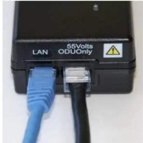
2 (a) Place the AC Power Injector on a horizontal surface. Plug the LPU to PSU drop cable into the PSU port labeled ODU.
(b) When the system is ready for network connection, connect the network Cat5e cable to the LAN port of the PSU:
(a)
(a)
Installing the AC+DC Enhanced Power Injector
Follow this procedure to install the AC+DC Enhanced Power Injector (Cambium part number C000065L002C):
1 Mount the AC+DC Enhanced Power Injector by screwing it to a vertical or horizontal surface using the four screw holes (two holes circled):

2 Form a drip loop on the PSU end of the LPU to PSU drop cable. The drip loop ensures that any moisture that runs down the cable into the cabinet or enclosure cannot enter the PSU.
3 (a) Undo the retaining screw, hinge back the cover and plug the drop cable into the port.
(b) Close the cover and secure with the screw.
(c) When the system is ready for network connection, connect the network Cat5e cable to the LAN port of the PSU:
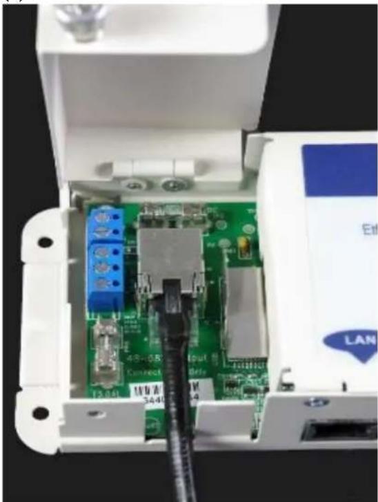
(a)
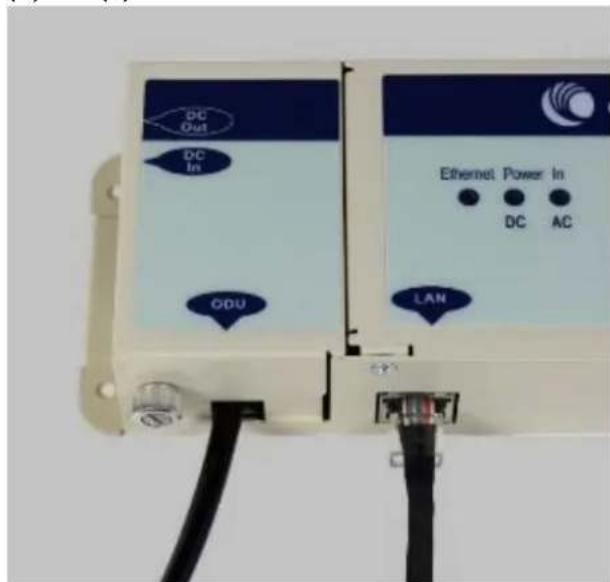
(b) and (c)
Configuring the ODU for operation in the EU
Generate a country-specific License Key
In the PTP 670 series, a License Key is used to activate new features, and to alter the regulatory settings of an ODU. The new License Key will include the regulatory bands allowed in the specified country of operation. Use this procedure to generate the License Key.
Procedure:
1 Navigate to the Cambium Support Center at:
https://support.cambiumnetworks.com/licenseskeys/ptp50670
2 Enter the ODU MAC Address and select the Country where the PTP link will be deployed.
3 Agree to the Terms and Conditions and click on Submit
4Locate the ODU by MAC address and copy the generated License Key from the License Keys page
5 Save the License Key (for example by pasting to a text editor and saving the file) for future use
Configure the management PC
Use this procedure to configure the local management PC to communicate with the PTP 670.
Procedure:
1 Select Properties for the Ethernet port. In Windows 10 this is found in Control Panel > Network and Internet > Network and Sharing Center > Change Adapter Settings. Right-click on the icon for the Ethernet adaptor and select Properties.
2 Select Internet Protocol Version 4 (TCP/IPv4):
3 Click Properties.
4 Enter an IP address that is valid for the 169.254.X.X network, avoiding 169.254.0.0 and 169.254.1.1. A good example is 169.254.1.3.
5 Enter a subnet mask of 255.255.0.0. Leave the default gateway blank.
Connect the ODU to the PC and powering up
Use this procedure to connect a management PC and power up the PTP 670.
Procedure:
1 Check that the ODU and PSU are correctly connected.
2 Connect the PC Ethernet port to the LAN port of the PSU using a standard (not crossed) Ethernet cable.
3 Apply mains or battery power to the PSU. The green Power LED should illuminate continuously.
4 After about 45 seconds, check that the orange Ethernet LED starts with 10 slow flashes.
5 Check that the Ethernet LED then illuminates continuously.
Logging into the web interface
Use this procedure to log into the web interface as a system administrator.
Procedure:
1 Start the web browser from the management PC.
2 Type the IP address of the unit into the address bar. The factory default IP address is 169.254.1.1. Press ENTER. The web interface menu and System Summary page are displayed.
3 On the menu, click Installation. The login page is displayed with Password only (the default) or with username and Password (if identity-based user accounts have been enabled). The default Password is blank.
4 EnterUsername(ifrequested)andPassword(the default isblank)and click Login.
Update the License Key and configure the ODU
Use this procedure to install a new License Key and to configure the antenna gain and cable loss in a Connectorized ODU.
Procedure:
1 On the menu, click Installation. Click on Continue to Installation Wizard.
2 On the Software License Key page, paste the License Key in the License Key attribute. Click Submit or Format.
3 For an Integrated ODU, click Next in successive pages until the Wireless Configuration page is displayed. Set the Regulatory Band and Maximum Transmitter Power attributes for operation in the selected band. Note that in some EU member states, the 5.4 GHz band may be the only band available.
Click Next in successive pages until the Confirm Installation Configuration page is displayed. Click Confirm Configuration and Reboot.
4 For a Connectorized ODU, click Next in successive pages until the Wireless Configuration page is displayed. Set the Regulatory Band, Antenna Gain, Cable Loss and Maximum Transmitter Power attributes to match the antenna and cables used in the installation. Note that in some EU member states, the 5.4 GHz band may be the only band available.
Click Next in successive pages until the Confirm Installation Configuration page is displayed. Click Confirm Configuration and Reboot.
Cambium Networks
Cambium Networks provides professional grade fixed wireless broadband and microwave solutions for customers around the world. Our solutions are deployed in thousands of networks in over 153 countries, with our innovative technologies providing reliable, secure, cost-effective connectivity that's easy to deploy and proven to deliver outstanding performance.
Our award-winning Point to Point (PTP) radio solutions operate in licensed, unlicensed and defined use frequency bands including specific FIPS 140-2 solutions for the U.S. Federal market. Ruggedized for 99.999% availability, our PTP solutions have an impeccable track record for delivering reliable high-speed backhaul connectivity even in the most challenging non-line-of-sight RF environments.
Our flexible Point-to-Multipoint (PMP) solutions operate in the licensed, unlicensed and federal frequency bands, providing reliable, secure, cost effective access networks. With more than three million modules deployed in networks around the world, our PMP access network solutions prove themselves day-in and day-out in residential access, leased line replacement, video surveillance and smart grid infrastructure applications.
Cambium Networks solutions are proven, respected leaders in the wireless broadband industry. We design, deploy and deliver innovative data, voice and video connectivity solutions that enable and ensure the communications of life, empowering personal, commercial and community growth virtually everywhere in the world.
User Guides: http://wwwCambiumnetworks.com/guides
Technical training: http://wwwCambiumnetworks.com/technical_training
Support website: https://support.cambiumnetworks.com
Main website: http://wwwCambiumnetworks.com
Sales enquiries: solutions@cambiumnetworks.com
Support enquiries: https://support.cambiumnetworks.com
Telephone number list: http://www.cambiumnetworks.com/contact-us/
Address: Cambium Networks Limited,
Linhay Business Park,
Eastern Road,
Ashburton,
Devon, UK
TQ137UP
phn-4835 000v002
December 2018

Cambium Networks
wwwCambiumnetworks.com
Cambium Networks and the stylized circular logo are trademarks of Cambium Networks, Ltd. All other trademarks are the property of their respective owners.
Copyright 2018 Cambium Networks, Ltd. All rights reserved.
Czech (CS)
Správnost
http://www.cambiumnetworks.com/support/wee-compliance
Bezpečnost

Linhay Business Park,
Eastern Road,
Ashburton,
http://www.cambiumnetworks.com/support/weee-compliance
Sécurité

https://support.cambiumnetworks.com/licenseskeys/ptp50670
Formation technique: http://wwwCambiumnetworks.com/technical_training
Site web d'assistance : https://support.cambiumnetworks.com
Site web principal : http://wwwCambiumnetworks.com
Demandes d'ordre commercial : solutions@cambiumnetworks.com
Informations assistance : https://support.cambiumnetworks.com
Linhay Business Park,
Eastern Road,
Ashburton,
Devon, Royaume-Uni
TQ137UP
phn-4835 000v002
Déprétre 2018

Cambium Networks
wwwCambiumnetworks.com
http://www.cambiumnetworks.com/support/compliance/
http://www.cambiumnetworks.com/support/wee-compliance
Seguridad

Cambium Networks Ltd, Unit B2 Linhay Business Park, Eastern Road, Ashburton, Devon, TQ13 7UP, Reino Unido.
Linhay Business Park,
Eastern Road,
Ashburton,
Devon, Reino Unido,
TQ137UP
phn-4835 000v002
Diciembre de 2018

Cambium Networks
wwwCambiumnetworks.com
http://www.cambiumnetworks.com/support/compliance/
http://www.cambiumnetworks.com/support/weee-compliance
Sicurezza

Cambium Networks Ltd, Unit B2 Linhay Business Park, Eastern Road, Ashburton, Devon, TQ13 7UP, United Kingdom.
https://support.cambiumnetworks.com/licenseskeys/ptp50670
Linhay Business Park,
Eastern Road,
Ashburton,
Devon, UK
TQ137UP
phn-4835 000v002
Dicembre 2018

Cambium Networks
wwwCambiumnetworks.com
http://www.cambiumnetworks.com/support/compliance/
http://www.cambiumnetworks.com/support/wee-compliance
Bezpieczenstwo

Cambium Networks Ltd, Unit B2 Linhay Business Park, Eastern Road, Ashburton, Devon, TQ13 7UP, Wielka Brytania.
Configuring the ODU for operation in the EU
Generate a country-specific License Key
https://support.cambiumnetworks.com/licenseskeys/ptp50670
http://www.cambiumnetworks.com/technical_training
https://support.cambiumnetworks.com
http://wwwCambiumnetworks.com
solutions@cambiumnetworks.com
https://support.cambiumnetworks.com
http://www.cambiumnetworks.com/contact-us/
Cambium Networks Limited,
Linhay Business Park,
Eastern Road,
Ashburton,
http://www.cambiumnetworks.com/support/weee-compliance
Güvenlik

Cambium Networks Ltd., Unit B2 Linhay Business Park, Eastern Road, Ashburton, Devon, TQ13 7UP, Birlesik, Krallik.
https://support.cambiumnetworks.com/licenseskeys/ptp50670
Adres: Cambium Networks Limited, Linhay Business Park, Eastern Road, Ashburton, Devon, Birlesik Krallik, TQ13 7UP
phn-4835 000v002
Aralik 2018

Cambium Networks
wwwCambiumnetworks.com
http://www.cambiumnetworks.com/support/weee-compliance
Személybiztonság

Cambium Networks Ltd, Unit B2 Linhay Business Park, Eastern Road, Ashburton, Devon, TQ13 7UP, United Kingdom (Egyesult Kiralysag).
https://support.cambiumnetworks.com/licenseskeys/ptp50670
Linhay Business Park,
Eastern Road,
Ashburton,

- CZECH (CS) 35
- Accuracy
- Copyrights
- Restrictions
- License Agreements
- High Risk Materials
- Notices
- About this Quick Start Guide
- Intended use
- Operation in the EU
- Restrictions and requirements for authorization for use
- Antennas for connectorized units
- Recommended parabolic dish antennas
- Configuration of the ODU
- Simplified EU Declaration of Conformity
- Professional installation
- User documentation
- Waste Electrical and Electronic Equipment (WEEE)
- Safety
- Grounding and protective earth
- DC supply
- Powering down before servicing
- Primary disconnect device
- External cables
- Drop cable tester
- RF exposure near the antenna
- Minimum separation distances
- Grounding and lightning protection requirements
- Grounding cable installation methods
- Siting ODUs and antennas
- Wind survival speeds
- Surface temperature
- Equipment manufacturer
- ODU variants and mounting bracket options
- Mounting bracket options
- Installing the ODU and top LPU
- Attach ground cables to the ODU
- Mount the ODU on the mast
- Tilt Bracket Assembly
- Tilt Bracket Assembly with band clamps
- Mounting bracket (Integrated)
- Mount the top LPU
- Interconnect and ground the ODU and top LPU
- Install external antennas for a Connectorized ODU
- Installing the copper Cat5e Ethernet interface
- Install the ODU to top LPU drop cable
- Connect the drop cable to the ODU (PSU port) and LPU
- Disconnect the drop cable from the LPU or ODU
- Install the main drop cable
- Cut to length and fit hoisting grips
- Terminate with RJ45 connectors and glands
- Hoist and fix the main drop cable
- Ground the main drop cable
- Install the bottom LPU to PSU drop cable
- Install the bottom LPU
- Install the LPU to PSU drop cable
- Test resistance in the drop cable
- Installing the PSU
- Installing the AC Power Injector
- Installing the AC+DC Enhanced Power Injector
- Configuring the ODU for operation in the EU
- Generate a country-specific License Key
- Procedure:
- Configure the management PC
- Connect the ODU to the PC and powering up
- Logging into the web interface
- Update the License Key and configure the ODU
- Cambium Networks
- Správnost
- Bezpečnost
- Sécurité
- Seguridad
- Sicurezza
- Bezpieczenstwo
- Güvenlik
- Személybiztonság
Brand : Cambium Networks
Model : PTP 670
Category : Telecommunication Equipment