WDF 20000 UV 18 - Water filter T.I.P. - Free user manual and instructions
Find the device manual for free WDF 20000 UV 18 T.I.P. in PDF.

| Product type | Water filter for garden pond |
| Brand | T.I.P. |
| Model | WDF 20000 UV 18 |
| Dimensions (L x W x H) | 57 x 37 x 45 cm |
| Net weight | approx. 10.9 kg |
| Pump power supply | 220 – 240 V~ / 50 Hz, 75 W |
| UV-C power supply | 230 V~ / 50 Hz, 22 W |
| Maximum flow rate | 4,000 l/h |
| Maximum head height | 3 m |
| Maximum immersion depth | 2 m |
| UV-C lamp | 18 W, type 2G11 |
| UV-C lamp lifespan | 4,000 hours (recommended every 5,000 h) |
| Maximum UV-C operating pressure | 0.3 bar |
| Pump protection class | IPX8 |
| UV-C protection class | IP44 |
| Maximum water temperature | 35 °C |
| Minimum water temperature | 5 °C |
| Recommended pond volume | up to 20,000 litres |
| Inlet connection | ∅ 25 mm (3 m corrugated hose included) |
| Outlet connection | ∅ 50 mm (2 m corrugated hose included) |
| Backwash connection | ∅ 25 mm |
| Pump cable length | 5 m, with Schuko plug |
| Article number | 30285 |
| Main functions | Mechanical filtration (sponge), biological (bioballs), UV-C sterilization, aeration (wet & dry plate) |
| Maintenance and cleaning | Clean sponges with running water, rinse bioballs, clean the wet & dry plate, use the backwash valve, replace UV-C lamp every 5,000 h |
| Safety instructions | Disconnect before maintenance, use a residual current device ≤ 30 mA, do not use when people are in the water, avoid direct contact with UV-C light, protect from frost |
| Spare parts and repairability | UV-C lamp and filter mats are wearing parts (not covered by warranty). Spare parts available at www.tip-pumpen.de |
| General information | Warranty: manufacturing defects; see conditions. After-sales service: contact the dealer. Disposal instructions according to WEEE directive. |
Frequently Asked Questions - WDF 20000 UV 18 T.I.P.
User questions about WDF 20000 UV 18 T.I.P.
0 question about this device. Answer the ones you know or ask your own.
Ask a new question about this device
Download the instructions for your Water filter in PDF format for free! Find your manual WDF 20000 UV 18 - T.I.P. and take your electronic device back in hand. On this page are published all the documents necessary for the use of your device. WDF 20000 UV 18 by T.I.P..
USER MANUAL WDF 20000 UV 18 T.I.P.
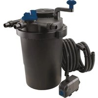
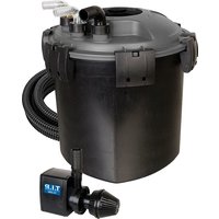
natural_image
Black industrial water heater with coiled tubing and a T.I.R. air purifier unit (no visible text or symbols)WDF 10000 UV 11
WDF 20000 UV 18
D Gebrauchsanweisung 01
TEICHAUSSENFILTER
GB Operating Instructions 09
EXTERNAL POND FILTER
CZ Uživatelský návod 17
VNĚJŠÍ FILTR RYBNÍKA
F Mode d'emploi 23
FILTRE EXTERNE ETANG
I Istruzioni per l'uso 27
STAGNO FILTRO ESTERNO
E Instrucciones para el manejo 31
FILTRO EXTERNO POND
H Használati utasítás 35
KÜLTÉRI TÓ SZÜRÖRENDSZER
PL Instrukcja użytkowania 38
ZEWNETRZNY FILTR STAWOWY
BG Упътване за употреба
ПОМПА ЗА ЕЗЕРО 42
RO Instructiuni de utilizare 45
FILTRU EXTERIOR DE IAZ
HR Upute za uporabu 48
VANJSKOG FILTRA ZA JEZERCE
SK Inštrukcie 51
RYBNIK EXTERNÉ FILTRE
SLO Navodila 54
RIBNIK ZUNANJI FILTRI
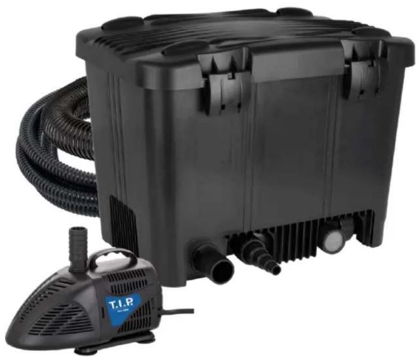
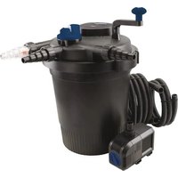
natural_image
Black industrial water purifier with coiled tubing and a T.I.P. label (no visible text or symbols on the device itself)GB EC declaration of conformity
We, T.I.P. Technische Industrie Produkte GmbH, Siemensstr. 17, D-74915 Waibstadt, declare in our sole responsibility that the products identified below comply with the basic requirements imposed by the EU directives specified below including all subsequent amendments: 2014/35/EU, 2014/30/EU, 2011/65/EU.
Pond filter with UV-C lamp
WDF 10000 UV 11
UV-C-PJ 11W
WDF 20000 UV18
UV-C 18W
Teichpumpe
pond pump
PKH 2600
PKH 4000
Strictly ensure that you have read the use instructions before placing the pump in service!
Congratulations for buying your new device from T.I.P.!
Like all our products, this one, too, was developed using the latest technological knowledge. The device was manufactured and assembled on the basis of state-of-the-art pump technology using most reliable electrical or electronic components which ensure a high level of quality and a long life of your new product.
Please read through these operating instructions carefully to make sure that you can fully benefit from all features.
Some explanatory illustrations can be found at the end of these operating instructions.
We hope you will enjoy your new device!
Table of contents
- General safety instructions.... 1
- Application areas and mode of operation.... 3
- Technical data.... 3
- Scope of delivery 4
- Installation....4
- Maintenance and care....5
- Warranty 7
- Service 8
- How to order spare parts....8

1. General safety instructions
Please read through these operating instructions carefully and make yourself conversant with the control elements and the proper use of this product. We shall not be liable in the case of damage caused as a result of the nonobservance of instructions and provisions of the present operating instructions. Any damage caused as a result of the nonobservance of the instructions and regulations contained in the present operating instructions shall not be covered by the warranty terms. Please keep these operating instructions in a safe place and hand them on together with the device should you ever dispose of it.
Persons not conversant with the contents of these operating instructions must not use this device.
The device must not be used by children.
The device may be used by persons with reduced physical, sensory or mental capabilities or lack of experience and / or knowledge if they have been supervised or instructed in the safe use of the equipment and have understood the resulting hazards. Children are not allowed to play with the device. Keep the appliance and its cord out of reach of children.
The device must not be used when people are in the water.
The device must be supplied through a residual current device (RCD) having a rated residual operating current not exceeding 30mA.
The supply cord of the devices cannot be repaired or fixed. Please replace the complete device, if the supply cord is damaged.
Notes and instructions with the following symbols require particular attention:

Danger of injury or material damage if this instruction is not complied with

Danger of electrical shock that can result in injury or material damage if this instruction is not complied with

In addition to the basic safety instructions, also comply with the following instructions to prevent accidents:
- ATTENTION! Before performing any installation or maintenance tasks, disconnect the electrical devices immersed in the pond from the power source by pulling the plug out of the socket outlet. Do not operate the pump if there are people in the water. Switch off the main fuse of the main domestic power supply, before unplugging the mains cable, if the connection plug or the main power outlet are wet. Never transport or suspend the device by the mains cable.
- Ensure that the voltage specified on the type plate of the device agrees with the mains voltage.
- Prior to connecting the device to the mains supply, ensure that the mains cable and the device are not damaged in any way.
- The mains cable of the device must form a loop that points downward (DRIP LOOP) to prevent water from running along the cable and into the socket outlet.
- The device must have a residual current circuit breaker (RCCB) with a rated residual current of max. 30 mA connected on the line side. Consult a qualified electrician.
- Do not bury the mains cable in the ground; follow the installation instructions specified in the applicable local regulations. Consult a qualified electrician.
- Prior to placing the device in service, ensure that the installation has been properly executed.
- Install the filter at least 2 meters away from the edge of the pond; ensure that it is attached in such a manner that it cannot accidentally fall into the water and that the installation area of the filter cannot be flooded.
- Do not use or store the device in areas where there is danger of freezing. In winter the device should be removed, emptied and stored where it is protected against freezing.
- Do not let the pump run dry (without water flow).
- Do not use the device with corrosive liquids.
- The temperature of the pumped liquid must not exceed 35°C (max.) and must not be under 2°C.

1.1. UVC FILTER
- ATTENTION! Only use the UVC filter together with the safety transformer included in the scope of delivery. If there is a defect, the complete UVC unit must be replaced.
- ATTENTION! This device emits UVC radiation that can harm eyes and skin. Do not use the bulb outside of the device
- ATTENTION! NEVER LOOK DIRECTLY INTO THE UVC TUBE WHEN IT IS SWITCHED ON
- ATTENTION! This device consists partially of glass! Handle with care!
- The max. temperature of the pumped liquid must not exceed 35^ C
- Never connect the filter to the public water supply network.
- The UV filter is not designed for immersion in water. If the device should accidentally fall into the water, do not, under any circumstances, attempt to get it out of the water, until you have pulled the mains plug out of the mains socket outlet. Also unplug the mains plug if you determine that the exterior of the device is wet.
- Do not operate the device with obvious defects.
- To prevent the lamp from overheating, switch it off when no water is running directly past.
- Warning. Stop using the UV C sterilizer temporarily during treatment with water and/or fish care products.


1.2. Pond pump
- Mains voltage and current type must agree with the information on the type plate.
- Install the connection socket outlet in the water-protected area and at least 2 m away from the edge of the pond.
• Unplug the mains plug before performing any work on the pump, fountain or pond. - Do not operate the pump if there are people in the water (disconnect the pump from the mains supply beforehand!)
- Important! If there is damage to the mains cables or the motor housing the complete pump is unusable and must be disposed of. Repair is not possible because the connecting cable is permanently cast in the motor housing.
- Never suspend or transport the pump by the mains cable.

- This pump is equipped with a permanent magnet, its magnetic fields can influence cardiac pacemakers, interfere with electrical / electronic components and delete the data on data carriers.
- People with cardiac pacemakers should always maintain a safety distance of at least 30 cm to the pump.

ATTENTION! Use in garden ponds and the protected area of garden ponds is only permitted if the installation complies with the valid regulations. Consult a qualified electrician. DO NOT use the pump in or on swimming pools!

2. Application areas and mode of operation
WDF 10000 / WDF 20000 are complete and compact filtering systems developed specifically to clean garden ponds. It's small size facilitates maintenance work and means it is easier to find space for it in the garden. Working together with the PKH 2600 / PKH 4000 pump, suitable for continuous duty, it purifies water in four successive stages:
– UV-C sterilizing filter, which eliminates bacteria and helps eliminate algae.
– mechanical filtering consisting of a decanting stage and subsequent filtration through sponges.
- aeration stage through wet & dry screen, which replenishes the water's oxygen levels and encourages gaseous exchange with the atmosphere.
- biological filtering, whereby the filter develops effectively on the surface to promote the growth of beneficial bacteria colonies.
This is how the systems keeps the water in your pond clear and clean. The devices has been developed for private use and not for industrial or commercial purposes.
The filter systems are used to support the biological self-cleaning of your garden pond. A satisfactory effect and function of these filter systems are influenced by various operating conditions. Factors, such as many fish, few plants, a lot of direct sunlight, low water volume, and a high level of contamination can negatively influence the mode of operation.
- Technical data
| Model | WDF 10000 UV 11 | WDF 20000 UV 18 |
| Voltage / frequency pump | 220 – 240 V~ / 50 Hz | 220 – 240 V~ / 50 Hz |
| Power of pump | 43 W | 75 W |
| Flow rate max. (Qmax) | 2,600 l/h | 4,000 l/h |
| Delivery height | 2.5 m | 3 m |
| Submersible depth max. ▽ | 2 m | 2 m |
| Degree of protection pump | IPX8 | IPX8 |
| Voltage / frequency UV-C emitter | 230 V~ / 50 Hz | 230 V~ / 50 Hz |
| Power UV-C emitter | 13 W | 22 W |
| UV-C tube (power / type) | 11 W / G23 | 18 W / 2G11 |
| Duration of action UV-C tube | 4000 h | 4000 h |
| Operating pressure max. UV-C emitter (pmax) | 0.3 bar | 0.3 bar |
| Degree of protection | IPX4 | IP44 |
| Length of the connecting cable - UVC emitter | 5 m | 5 m |
| Maximum temperature of the pumped liquid (Tmax) | 35 °C | 35 °C |
| Minimum temperature of the pumped liquid | 5 °C | 5 °C |
| For ponds up to | 10,000 l | 20,000 l |
| Weight (net) | ~ 7.4 kg | ~ 10.9 kg |
| Filter dimensions, mounted (W x D x H) | 46 x 29 x 36 cm | 57 x 37 x 45 cm |
| Filter inlet | ∅ 25 mm | ∅ 25 mm |
| Filter outlet | ∅ 32 mm | ∅ 50 mm |
| Backwash | ∅ 25 mm | ∅ 25 mm |
| Item number | 30495 | 30285 |

4. Scope of delivery
T.I.P. external pond filter:
WDF 10000 UV 11 W: filter container, Bioballs, Wet-and-Dry unit, back wash, UVC emitter 11 Watt, 1 sponge, 3 m spiral hose (ø 25 mm), 2 m spiral hose (ø 32 mm), pump PKH 2600, operating instruction. WDF 20000 UV 18 W: filter container, Bioballs, Wet-and-Dry unit, back wash, UVC emitter 11 Watt, 1 sponge, 3 m spiral hose (ø 25 mm), 2 m spiral hose (ø 50 mm), pump PKH 4000, operating instruction. Check the device for transport damage and complete delivery. If there is damage the retailer must be notified without delay, at the latest however, within 8 days of the purchase date. If possible, dispose the packaging until the end of the warranty period. Dispose of packaging materials in an environmentally friendly manner.

5. Installation
Do not use excessive force that can cause damage when tightening threaded unions.
The numbers and other information cited below in parentheses are based on this illustration.

5.1. Mounting
Install the UV-C sterilizer in the compartment under the case, fastening it with the relevant fittings and rubber seal as illustrated in appendix (A, B, C)
- Install the drain valve (4) with the relevant fitting (3) and seal (5) as illustrated in appendix (C)
- Install the outlet fitting (8) with the relevant fitting (7) and seal (6) as illustrated in appendix (C)
– Position the sponge (3) as illustrated in appendix (D) - Place the biological filtering material (Bioballs) (2) in the relevant compartment as illustrated in appendix (D)
– Position the wet-and-dry perforated screen (1) as illustrated in appendix (D) - Assemble the cover with the 2 pipes (WDF 10000, 6) / 8 pipes (WDF 20000, 6) and sponge retaining grid (5). (E)
- INLET connection: connect the pump (9) with the hose-end fitting and 3m spiral hose (10) to the UV-C sterilizer's inlet as illustrated in appendix (F). When necessary, use a clamp to make the connection more secure.
- Suggestion for WDF 10000: Adjust the hose connection ports to the size of the hose that is used; to do this, use a standard household saw to cut off the smaller hose diameter that is not required on the connection ports.
- OUTLET connection: connect the 2m spiral hose (11) to the outlet fitting as illustrated in appendix (F). When necessary, use a clamp to make the connection more secure.
- Determine which point near the pond makes the best location, bearing in mind the lengths of the pipes supplied.
- Switch on the pump, check to see that the filter fills and that water comes out of the outlet correctly. It is not a problem if the sponge rises since the grid located on the cover will keep it in the correct working position.
- Close the cover.
- Switch on the UV-C sterilizer and check that the lamp is working through the opaque glass screen.
Warning
- The filter must always be positioned above the pond's water level.
- Place the filter horizontally (to prevent water overflowing).
- To encourage water to leave the filter, the outlet pipe must never be higher than the level of the connection hole it comes from.
- If there is any overflowing, make sure that the wet-and-dry screen (D 1) and the filter in the discharge chamber are clean.
- If there is any overflowing, make sure that the wet-and-dry screen and the filter in the discharge chamber are clean.
5.2. Setting up at the garden pond
Place the filter above the water level (filter outflow at least 15 cm above the water surface) and ensure that the filter is at least 2 meters away from your pond. The container should be placed horizontally on a solid substrate (stone slab). Ensure, that it cannot fall into the water and that the installation area of the filter cannot be flooded.
It is best to set up the filter where it is in the shade. If the interior of your filter should become very hot, then its capacity is reduced.
To ensure safe operation, we recommend that you fix the hose ends in place on the hose connection pieces with off-the-shelf hose clamps.
Always use the shortest possible hose length and avoid kinking the hose
For biological reasons, the immersion depth of the pond pump should be approx. 40 cm for optimal function of the filter system. Ensure that the pond pump is placed on a silt-free substrate (stone slab).
5.3. Placing in service
Attention! Comply with the safety measures specified for the UVC emitter and the pump (see above)! (See the provided operating instructions).
Install the connection socket outlet in the water-protected area and at least 2 m away from the edge of the pond!
Connect the pond pump to the mains supply, plug the mains plug into the socket outlet.
The pond pump pumps the contaminated water into the filter through the UVC emitter
Connect the UVC emitter to the mains supply, plug the mains plug into the socket outlet.
You can check the function of the UVC tube through a bluish shimmer on the transparent discharge port of the UVC emitter.
For this filter system we recommend continuous operation (24 hours a day), in the season months March to October.
Note: - The biological filtration develops naturally, it takes 5-6 weeks until the full
effect is attained. To accelerate settlement of bacteria, appropriate bacteria can be purchased in any pond shop.
Attention! The function of the filter system must be checked at regular intervals!
Initially the filter system should be checked at least 1x daily. Leaves, grass, and animal hair, for example can quickly clog the filter sponges.
Consequently select the cleaning intervals based on the type and the extent of contamination in your pond.

6. Maintenance and care

Attention! Prior to carrying out any maintenance work, the electric device must be separated from the electrical mains.

Attention! The power cord of this device cannot be replaced. If the cable is damaged the UVC emitter contained in the filter, including the ballast, is unusable and must be properly disposed of. Repair is not possible because the connecting lines are permanently cast.
6.1. Cleaning the pump
– always disconnect the power supply before performing any maintenance work
- make sure the pump's filter cap (Fig. PKH 2600 / 4000, 1) is not entirely clogged by leaves or other debris. If it is, clean the housing.
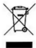
- Press the side of the front cover (1) and pull it off the pump (Fig. 1)
- Twist the inlet cover (9) counterclockwise by approx. 20^ (Fig. 2)
- Pull the inlet cover (9) out of the pump.
- Pull the rotor completely (7, 10, 11) out of the pump.
Note: The impeller and the magnet can be rotated by a certain angle against each other for technical reasons
- Mount the pump as follows:
5.1. Insert the rotor completely (7, 10, 11) into the pump.
5.2. Twist the inlet cover (9) into the pump and turn clockwise until it stops.
5.3. Insert the front cover (1) into the pump.
For proper operation, repeat this procedure depending on the degree of soiling and service life.
6.2. Cleaning the UVC emitter and replacing the tube
Caution! Do not touch UVC tube (5) directly with your hand; put on cotton gloves!
Old UV-C tubes shall not get broken and must not be disposed in regular garbage bin. Contact your local waste disposal company. Do not use a sharp edged tools. In case Quartz glass cylinder or O-ring are defect, they should get replaced immediately.
The lamp must be changed by qualified personnel only.
GB
If you notice an increase in algae formation and/or see that lime scale is increasing, you will need to check that the UV-C unit is working properly. UVC tube (Fig. UV-C 11 W, 2 / Fig. UV-C 18 W, 5) has a limited period of effectiveness (approx. 4000 to 5000 hours) and should be replaced at the latest after one season (March to October). Appropriate replacement tubes are available at the service address specified below. If the pond filter has been switched off for a longer period of time, ensure that the quartz glass cylinder (Fig. UV-C 11 W, 3 / Fig. UV-C 18 W, 2) that encloses the UVC tube is clean.
If the filter has not been operated for a longer period of time, under some circumstances it may be necessary to replace the sealing rings (particularly for the UVC emitter).
Cleaning of the UV-C lamp
- Disconnect the UVC lamp from the mains power and safeguard it from being switched on unintentionally
- Comply with the safety measures.
- Allow the water to completely run out of the unit.
- Dismantle the UVC lamp. Take the lamp out of the compartment in the filter housing.
6.2.1. Cleaning of the quartz glass cylinder UV-C 11W (WDF 10000 UV 11)
- After removing the lamp socket (1) and UVC tube (2), carefully pull the quartz glass (3) out of the housing. Use a wide screwdriver, a coin or similar item to do so. Insert the tool into one of the notches visible at the beginning of the housing thread and carefully pry out the quartz glass.
- Clean the quartz glass (3) and the housing (5) thoroughly with water and a soft cloth.
- Use a suitable solvent to remove any lime deposits on the quartz glass (3). Rinse thoroughly before installation.
- Check the quartz glass for damage. A defective quartz glass must always be replaced.
Fit everything in reverse order.
Make sure that the O-ring (4b) is properly seated in the corresponding groove in the housing and the thinner O-ring (4a) in the quartz glass socket. Grease the O-rings with Vaseline if required. Push the quartz glass completely into the housing of the lamp. Check that the protective cap is fitted onto the tube (7). Push the lamp socket with the UVC tube carefully into the quartz glass and tighten the socket firmly by hand.
6.2.2. Replacing the UV-C lamp UV-C 11W (WDF 10000 UV 11)
-
Always switch off the power supply by pulling the mains plug before maintenance work.
-
Unscrew the bulb socket (1) of the lamp housing, remove the UVC tube (2) and replace the old tube with a new one. Fit everything in reverse order (see above) and be sure that the O-rings are correctly fitted. Grease the O-rings with Vaseline if required.
Caution! Do not touch UVC tube (2) directly with your hand; put on cotton gloves!
Old UV-C tubes shall not get broken and must not be disposed in regular garbage bin. Contact your local waste disposal company. Do not use an sharp edged tools. In case Quartz glass cylinder or O-ring are defect, they should get replaced immediately.
6.2.3. Function check of UVC lamp UV-C 11W (WDF 10000 UV 11)
You can check the function of the UVC tube by the bluish shimmer on the transparent hose connection (6) of the UVC emitter. This check works best in low light.
If the UV-C tube does not burn, the UV-C lamp may not have been assembled correctly.
Check this using the installation instructions above.
6.2.4. Cleaning of the quartz glass cylinder UV-C 18W (WDF 20000 UV 18)
- Unscrew the base (3) of the plastic housing (1) of the lamp and replace the UV-C tube (5) if necessary
- After disassembling the lamp socket (3) and UV-C tube (5) take carefully the quartz glass (2) out of the housing (1). You may use a wide screw driver or a coin. Insert the tool into the recess, which is at the end of the thread of the protective sleeve and lift it carefully out.
- Clean the quartz glass (2) and housing (1) thoroughly with water and a soft cloth.
- If needed, remove lime scale from the quartz glass (2) with a suitable solvent. Rinse out thoroughly before reassembling.
- If quartz glass tube or O-rings are defective they must always be replaced
6.2.5. Replacement of the UV-C lamp: UV-C 18W (WDF 20000 UV 18)
-
Unscrew the base (3) of the plastic housing (1) of the lamp, remove the UV-C bulb (5) and replace the old one with a new one.
-
Reassemble in the reverse order, making sure you position the O-rings correctly. When necessary, grease O-rings with Vaseline.
- If quartz glass tube or O-rings are defective they must always be replaced
6.2.6. Function check of UVC lamp UV-C 18W (WDF 20000 UV 18)
In case the UVC lamp does not shine, the micro switch might not be activated. The UVC lamp should get completely reassembled.
- Assemble UV-C tube (5) including Quartz glass (2) to lamp socket (3).
- Make sure O Ring (2a) is inserted.
- Pull the protective housing (1) over the UV-C tube and Quartz glass and connect to the socket. By doing so the micro switch should get active automatically.
The UVC tube works properly if you see a bluish light at the end of the viewing glass (6).
6.3 Cleaning of filter
Replace the filter mat (Fig. WDF 10000 D 3 / WDF 20000 D 3, 4) regularly (1 x pro Saison)
If you discover a deterioration of the water quality or too low flow rate or water coming out of the lid of the filter, the following steps should be done:
1) On the bottom of the filter housing larger amounts of dirt particles get collected over the time. These must be removed:
- Let pump continue to operate
- Open the back wash (Fig, C, 4) for approx. 10 sec, then shut off the pump, until filter is completely empty.
- Switch on the pump in order to remove remaining residues and dirt. Repeat this procedure until clear water runs out of the filter. Then close the back wash.
2) Mechanical sponge filter: Take the sponge / the sponges (Fig. WDF 10000 D 3 / Fig. WDF 20000 D,
3,4) out of the filter and clean them with clear water. Insert the sponge / sponges in the correct horizontal position.
3) Wet-and-dry screen (Fig. D, 1). The screen holes should not get clogged by debris and filaments at all times in order to allow the water to flow thoroughly.
4) Biological Filter: the Bioballs (D, 2) should be rinsed out, if the amount of debris has increased strongly
5) Make sure the outlet grid is unobstructed. (Fig. E, 5)
Annual maintenance: Carefully clean the filter at least once per year.
Empty the filter completely. Remove the dirt and debris from the bottom. Rinse out all filter materials with water.

Winter - maintenance
- Protect your pond filter from freezing!
• If there is danger of freezing, take the pump out of your garden pond. - Completely clean the pump as specified in the instructions.
• Store the pump over winter in a frost-free location

7. Warranty
The present device was manufactured and inspected according to the latest methods. The seller warrants for faultless material and workmanship in accordance with the legal regulations of the country in which the device was purchased. The warranty period begins with the day of the purchase and is subject to the provisions below:
Within the period of warranty, all defects which are to be attributable to defective materials or manufacturing will be eliminated free of charge. Any complaints are to be reported immediately upon their detection.
The warranty claim becomes void in the case of interventions undertaken by the purchaser or by third parties. Damage resulting from improper handling or operation, incorrect setting-up or storage, inappropriate connection or installation or Acts of God or other external influences are excluded from warranty.
Parts subject to wear, such as the UV bulb and filter mats are excluded from the guarantee.
All parts were manufactured using maximum care and high-quality materials and are designed for a long lifecycle. It should be understood, however, that the wear and tear depends on the kind of use, the intensity of use and the internals of maintenance.
GB
Complying with the installation and maintenance information contained in the present operating instructions will therefore considerably contribute to a long lifecycle of these wearing parts.
In case of complaints, we reserve the option of repairing or replacing the defective parts or replace the entire device. Replaced parts will pass into our property.
Claims for liquidated damages are excluded unless they are caused by wilful acts or negligence on the side of the manufacturer.
The warranty does not provide for any claims beyond those referred to above. The warranty claim has to be evidenced by the purchaser in the form of the submission of the sales receipt. The present warranty commitment is valid in the country in which the device was purchased.
Please note:
- Should your device fail to function properly, please verify first whether an operating error or another cause is present which cannot be attributed to a defect of the device.
- In case you have to take or send in your defective device for repair, please be sure to enclose the following documents:
– Sales receipt (sales slip).
- A description of the occurring defect (a description as accurate as possible will expedite the repair work).
- In case you have to take or send in your defective device for repair, please remove any attached parts which do not belong to the original condition of the device. If any attached parts of this kind should be missing upon the return of the device, we shall not be liable for them.

8. Service
In the case of warranty claims or malfunction, please contact your point of sale.

9. How to order spare parts
The fastest, most simple and cheapest way of ordering spare parts is through the internet. On our www.tip-pumpen.de website you will find a convenient spare part shop where you can order spare parts with just a couple of clicks. In addition, this is also the place where we publish comprehensive information and valuable tips on our products and accessories, introduce new devices and present current trends and innovations in the range of pump technology.
A current operating manual is available as required as a PDF file via e-mail: service@tip-pumpen.de.
For EU countries only
Please do not dispose of electrical appliances in the regular domestic waste!
According to the European Directive 2012/19/EU regarding waste electrical and electronic equipment and the implementation of that directive into national law, electrical devices have to be collected separately and disposed of in an environmental-suitable manner after the end of their life cycle. Should you have any questions, please contact your local waste disposal company.

service@tip-pumpen.de.
natural_image
Close-up of hands operating a black handheld power tool (no visible text or symbols)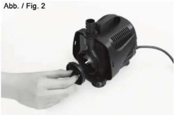
natural_image
Hand inserting a black plastic pump into a small component (no text or symbols visible)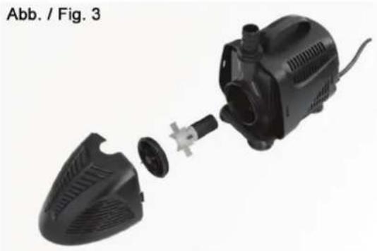
natural_image
Exploded view of a black industrial pump assembly with internal components (no text or symbols visible)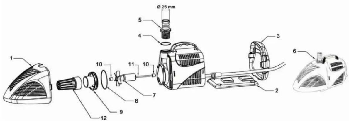
D – 74915 Waibstadt / Germany
service@tip-pumpen.de
www.tip-pumpen.de