
PMA 8000 UV 9 - Water filter T.I.P. - Free user manual and instructions
Find the device manual for free PMA 8000 UV 9 T.I.P. in PDF.

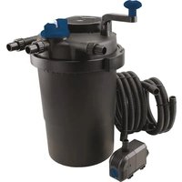
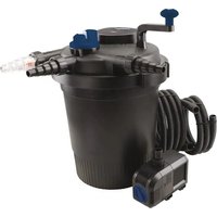
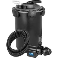
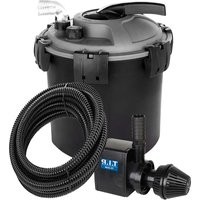
| Product type | Pressure filter for ponds with integrated UV-C clarifier |
| Brand | T.I.P. |
| Model | PMA 8000 UV 9 |
| Recommended pond volume | Up to 8,000 litres |
| Filter dimensions (L x W x H) | 38.5 x 43 x 38.5 cm |
| Net weight | 6.4 kg |
| Power consumption (pump) | 55 W |
| Power consumption (UV-C lamp) | 13 W |
| Voltage/frequency | 230-240 V~ / 50 Hz |
| Max. flow rate (pump) | 2,400 l/h |
| Max. delivery head | 2.5 m |
| Max. immersion depth (pump) | 3.0 m |
| Protection type (pump) | IP68 / Class I |
| Protection type (UV-C lamp) | IPX4 / Class I |
| Max. liquid temperature | 35 °C |
| Power cable length (pump) | 10 m |
| Power cable length (UV-C) | 5 m |
| Delivery contents | Filter tank, pump, BIOMEC filter mats, Bioballs, UV clarifier with ballast, 5 m hose (∅ 20 mm), manual |
| Filtration materials | Mechanical (sponges), biological (Bioballs), UV-C (9 W / G23 tube) |
| Filter inlet/outlet | ∅ 20 mm |
| Cleaning | Integrated backwash system |
| UV-C lamp lifespan | Approx. 4,000 hours (one season) |
| Frost protection | Store frost-free in winter |
Frequently Asked Questions - PMA 8000 UV 9 T.I.P.
User questions about PMA 8000 UV 9 T.I.P.
0 question about this device. Answer the ones you know or ask your own.
Ask a new question about this device
Download the instructions for your Water filter in PDF format for free! Find your manual PMA 8000 UV 9 - T.I.P. and take your electronic device back in hand. On this page are published all the documents necessary for the use of your device. PMA 8000 UV 9 by T.I.P..
USER MANUAL PMA 8000 UV 9 T.I.P.
natural_image
Black industrial vacuum cleaner with coiled hose and side connectors (no visible text or symbols)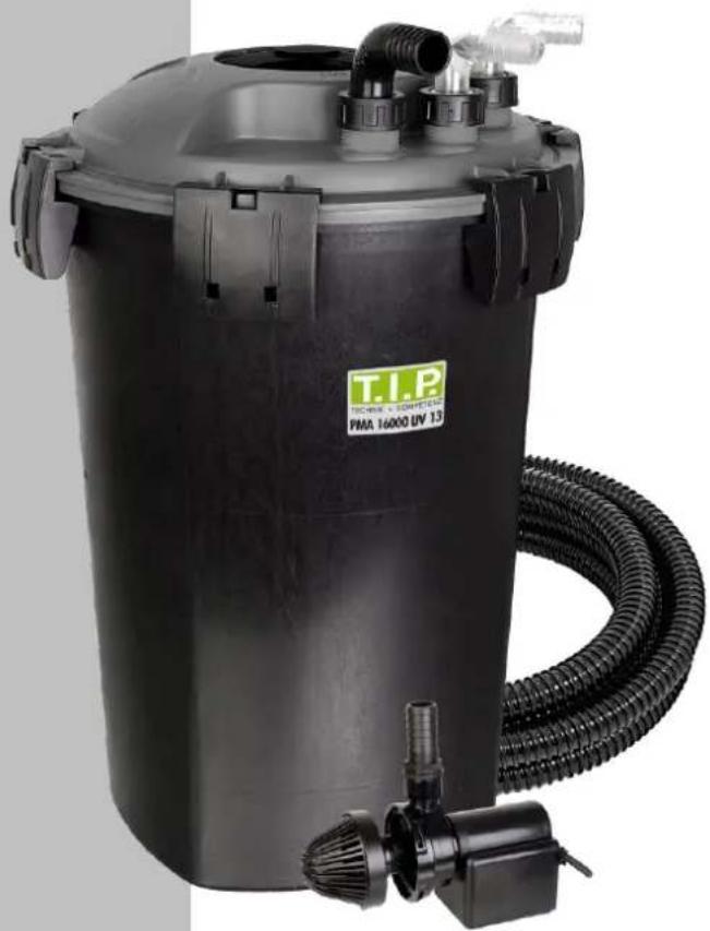
natural_image
Black industrial vacuum cleaner with coiled hose and inlet/outlet pipes (no visible text or symbols)D Gebrauchsanweisung Teichdruckfilter 01
F Mode d'emploi Filtre à pression pour étang 09
Istruzione per l'uso Filtro a pressione per stagni 17
GB Operating Instructions 24
Pond pressure filter
E Instrucciones para el manejo 27
Estanque de filtro de presión
H Használati utasítás Tavi nyomásszűrő 32
PL Instrukcja użytkowania Filtr ciśnieniowy do stawów 35
CZ Uživatelský návod
Tlakový filtr pro jezírka 39
BG Упътване за употреба Филтър под налягане 42
RO Instructiuni de utilizare Filtru de presiune pentru lac cu reflector UV-C și pompă 46
Upute za uporabu
HR Tlačni filtar za jezerce sa UV-C 50 emiterom i crpkom
Návod na použitie
SK Tlakový filter pre jazierka s UV- 53
C žiaričom a čerpadlom
Navodila za uporabo
SLO Tlačni filter za vrtno jezerce 57
GB EC declaration of conformity
We, T.I.P. Technische Industrie Produkte GmbH, Siemensstr. 17, D-74915 Waibstadt, declare in our sole responsibility that the products identified below comply with the basic requirements imposed by the EU directives specified below including all subsequent amendments: 2014/35/EU, 2014/30/EU, 2011/65/EU.
Pond filter with UV-C lamp
PMA 8000 UV 9
PMA 16000 UV 13
Teichpumpe
pond pump
TX 2500
TX 3800
natural_image
Top-down view of a circular mechanical component with internal features and connectors (no visible text or symbols)natural_image
Top-down view of a mechanical component with visible internal structure and two metallic fittings (no text or symbols)
Nur für EU-Länder
Fig. 4
E-mail : service@tip-pumpen.de
natural_image
Top-down view of a circular mechanical component with internal channels and connectors (no visible text or symbols)
Fig. 3
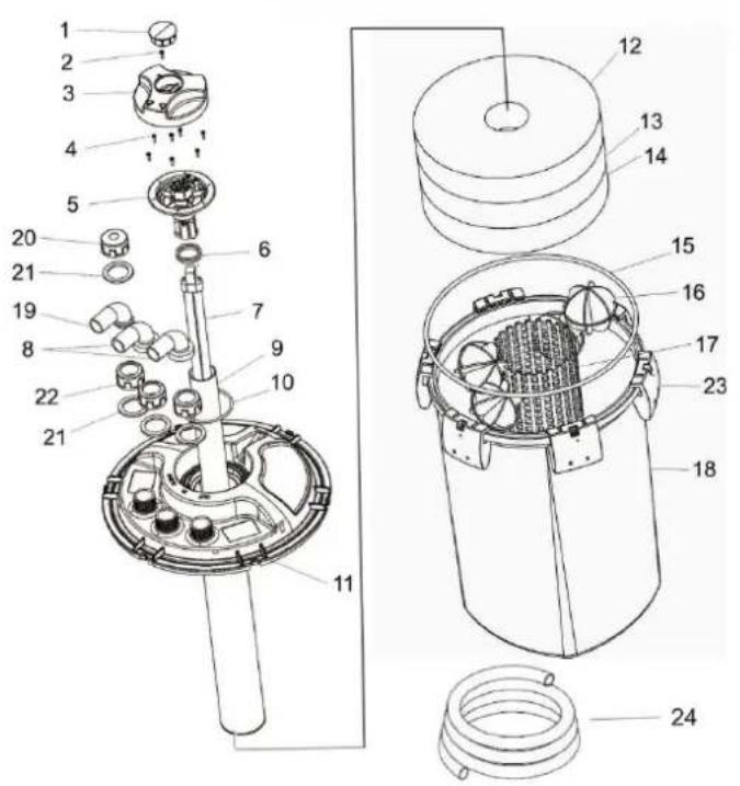
Fig. 4
Read the following instruction carefully before attempting to use. Keep for future reference.

Sect. 1 - Introduction
PMA 8000/16000 is a compact pressure filter for small lakes and ponds. It is easy to set and maintain. It consists of three different filtering systems:
- Mechanical filter Consisting of a large mass filter which enables blockage of solids. Helps in the cleaning and sanitizing of water for both plants and fishes.
- Biological filter Consisting of exceptional porous particles which provide an ideal environment for an intense build-up of bacterial colonies. These aid in the elimination of ammonia and nitrite
- UV-C filter. A UV-C filter which is protected by a quartz tube. Aids in the elimination of the green patina which commonly forms in ponds.

Sect. 2 - Safety rules
Persons not conversant with the contents of these operating instructions must not use this device.
This appliance can be used by children aged from 8 years and above and persons with reduced physical, sensory or mental capabilities or lack of experience and knowledge if they have been given supervision or instruction concerning use of the appliance in a safe way and understand the hazards involved. Children shall not play with the appliance. Cleaning and user maintenance shall not be made by children without supervision.
The pump must not be used when people are in the water.
The pump must be supplied through a residual current device (RCD) having a rated residual operating current not exceeding 30mA.
The mains power connection of this device cannot be replaced. In case the line is damaged, the device must be scrapped.
- Check that the voltage of product match that of the power source. Product should be operated only after proper instalment. The electrical safety of this product is ensured only when it is efficiently grounded.
- Before connecting the product to the power network, make sure that cables are not damaged.
-
Power supply cables must not be replaced or repaired. If damaged, entire product needs replacement.
-
WARNING: unplug all the immersed electrical appliances before attempting any maintenance in water. Should the connection plug or socket become wet, disconnect general power supply before unplugging power supply cable.
-
If appliance is unused during the winter months, remove to avoid freezing.
-
To avoid overheating, turn the lamp off when water is not circulating through the filter.
-
It is important to protect appliance with safety switch. Current should not exceed 30 mA.
-
Appliance must not be utilized for uses other than those for which it was designed.
-
Use of extension cables are not recommended. Should an extension cable be required, connection must be water-tight; the cable should also be suitable for outdoor use and be equivalent to that of appliance in terms of insulation and section.
-
To avoid unintentional wetting plug or socket, the cable should form a loop below the water level (see figure "Drip loop").
-
When installing and caring for appliance, avoid lifting from power supply cable.
-
Avoid operating appliance with the use of corrosive or abrasive liquids.
-
Do not dry operate in order to avoid damage to UV components.
-
Do not operate the product using liquids whose temperature exceed 35°C.
-
Never gaze directly into an illuminated UV lamp.
-
Keep these instructions for future reference.
-
Keep out of reach of children.

Sect.3 - Installation
- Determine most appropriate spot in which to position filter. Remember that appliance should not be placed further than 2m from the edge of pond.
- The filter can be placed underground up to the height of the hooks. The hooks themselves must be kept uncovered.
- Connect the pump in the filter's adjustable hose marked "IN" - (8) with a flexible tube.
- Connect a flexible tube to the adjustable hose marked "OUT" (8) to direct the stream as needed.
- Screw the cap (8B) to its o-ring (8C) to point marked "CLEAN".
- WARNING: the gap between the spring and the water surface must not be greater than 1m.
The filter is now ready to use. Simply switch on the pump and connect the UV-C lamp's power supply cable.

Caution
Temporarily suspend the use of the UV sterilizer if treating either water or fish.
- If the capacity of pump is higher than what is specified on the table, use a 2-way valve to regulate flow.

Sect. 4 Maintenance
Clean filter regularly.
If the water flow decreases, clean both filter and pump.
The filter is equipped with a quick cleaning system called "Back Wash".
- Always turn off the pump before acting on the valve.
- Connect flexible tube to black adjustable hose marked "CLEAN" - 8A; replace cap (8B); direct tube away from pool. The water can be used to irrigate garden.
- Turn on pump again. Rotate handle from working position (fig. A) to cleaning position (fig. B).
- Let water flow until it becomes clear.
- Place handle back on working position.
- When pump is off, remove the additional tube and put the cap back in place (8B). Twice yearly, clean the filter completely and internally.
- Turn off filter and open lid.
- Clean the inside.
- Rinse the sponges and bio-balls in tank with pond water (do not use tap water). Replace the sponges if damaged or worn.
Do ndusesolvents or cleaning agentstocleanfilterandfilteringcomponents. Use pond water only.
If algae formation increases, verify that UV-C appliance is working properly.
To ensure maximum efficiency, UV-C lamp (7) should be replaced after 5000 working hours. If lamp is working properly, clean quartz tube in which it is placed.
Before attempting any maintenance, unplug any appliances immersed in pond from the power source.
- Check that pump and lamp's power supply are off.
- Turn handle (3) onto working position.
- Remove lid (1) and screw (2).
- Lift handle (3) and remove screws (4).
- Lift lamp socket (5) being careful not to lose o-ring (10). - Do not pull power cable.
- Clean quartz glass tube (9); remove any lime scale deposits with decaling agents.
To replace lamp:
- Extract tube (9) from socket (5) pulling gently.
- Replace lamp (7).
- Check that components are dry.
-Place tube (9) back into socket (5); check that o-rings (6) are undamaged and properly repositioned.
- Mount o-ring (10) on socket (5); insert both in lid (11).
- Turn on lamp to verify that it is functioning. Light will be seen in transparency.
- Tighten screws (4), mount handle (3) by placing it in working position.
- Tighten screw (2) and mount lid (1).
Sect. 5 – Warranty
The present device was manufactured and inspected according to the latest methods. The seller warrants for faultless material and workmanship in accordance with the legal regulations of the country in which the device was purchased.
The warranty period begins with the day of the purchase and is subject to the provisions below:
Within the period of warranty, all defects which are to be attributable to defective materials or manufacturing will be eliminated free of charge. Any complaints are to be reported immediately upon their detection.
The warranty claim becomes void in the case of interventions undertaken by the purchaser or by third parties.
Damage resulting from improper handling or operation, incorrect setting-up or storage, inappropriate connection or installation or Acts of God or other external influences are excluded from warranty.
Parts subject to wear, such as the UV bulb and filter mats are excluded from the guarantee.
All parts were manufactured using maximum care and high-quality materials and are designed for a long lifecycle. It should be understood, however, that the wear and tear depends on the kind of use, the intensity of use and the internals of maintenance.
Complying with the installation and maintenance information contained in the present operating instructions will therefore considerably contribute to a long lifecycle of these wearing parts.
In case of complaints, we reserve the option of repairing or replacing the defective parts or replace the entire device.
Replaced parts will pass into our property.
Claims for liquidated damages are excluded unless they are caused by wilful acts or negligence on the side of the manufacturer.
The warranty does not provide for any claims beyond those referred to above. The warranty claim has to be evidenced by the purchaser in the form of the submission of the sales receipt. The present warranty commitment is valid in the country in which the device was purchased.
Please note:
- Should your device fail to function properly, please verify first whether an operating error or another cause is present which cannot be attributed to a defect of the device.
- In case you have to take or send in your defective device for repair, please be sure to enclose the following documents:
a. Sales receipt (sales slip).
b. A description of the occurring defect (a description as accurate as possible will expedite the repair work).
- In case you have to take or send in your defective device for repair, please remove any attached parts which do not belong to the original condition of the device. If any attached parts of this kind should be missing upon the return of the device, we shall not be liable for them.
Service
In the case of warranty claims or malfunction, please contact your point of sale.
How to order spare parts
The fastest, most simple and cheapest way of ordering spare parts is through the internet. On our www.tip-pumpen.de website you will find a convenient spare part shop where you can order spare parts with just a couple of clicks. In addition, this is also the place where we publish comprehensive information and valuable tips on our products and accessories, introduce new devices and present current trends and innovations in the range of pump technology.
A current operating manual is available as required as a PDF file via e-mail: service@tip-pumpen.de.
Technical Data
| Model | PMA 8000 UV 9 | PMA 16000 UV 13 |
| Voltage / frequency pump 230 V~ / 50 Hz 230 V~ / 50 Hz | ||
| Performance pump 55 W 70 W | ||
| Degree of protection / protection class of pump IP68 / I IP68 / I | ||
| Max. flow rate (Qmax) 2.400 l/h 3.800 l/h | ||
| Max. delivery height (Hmax) 2.5 m 2.6 m | ||
| Max. submersible depth ∇3.0 m 3.0 m | ||
| Power Cord Pump 10 m H05RN-F 10 m H05RN-F | ||
| Voltage / frequency UV-C emitter | 230 V / 50 Hz | 230 V / 50 Hz |
| Power consumption of UV-C emitter complete | 13 W | 15 W |
| Power consumption of UV-C tube | 9 W | 13 W |
| Degree of protection / protection class of UV-C emitter | IPX4 / I | IPX4 / I |
| Length of power cord of UV-C emitter | 5 m | 5 m |
| Weight (net) | 6.4 kg | 7.8 kg |
| Maximum temperature of the pumped liquid (Tmax) | 35°C | 35°C |
| Recommended for ponds up to max. | 8,000 l | 16,000 l |
| Filter dimensions (W x D x H) | 38.5 x 43 x 38.5 cm | 38.5 x 59 x 38.5 cm |
| Filter inlet | ∅ 20 mm | ∅ 25 mm |
| Filter outlet | ∅ 20 mm | ∅ 25 mm |
| Item number | 30286 | 30287 |
For EU countries only
Please do not dispose of electrical appliances in the regular domestic waste!
According to the European Directive 2012/19/EU regarding waste electrical and electronic equipment and the implementation of that directive into national law, electrical devices have to be collected separately and disposed of in an environmental-suitable manner after the end of their life cycle. Should you have any questions, please contact your local waste disposal company.
service@tip-pumpen.de.
Tehnični podatki:
Fig. 4
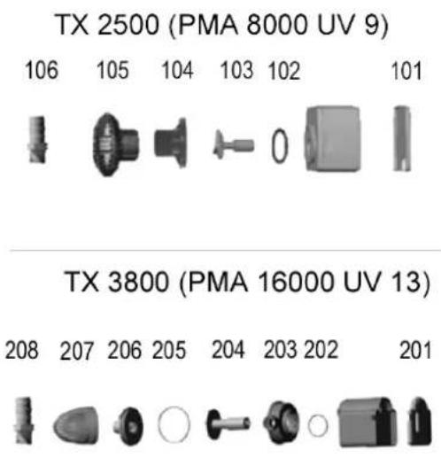
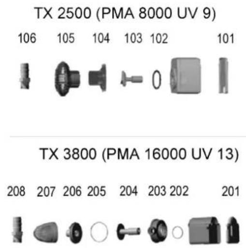
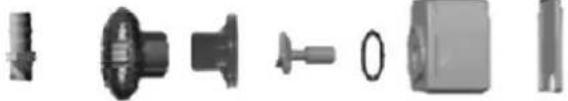
TX 2500 (PMA 8000 UV 9)

natural_image
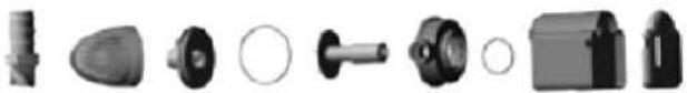
Collection of mechanical parts including gears, shafts, and housing (no visible text or symbols)TX 3800 (PMA 16000 UV 13)

natural_image
Collection of various mechanical components and parts, including a knob, washer, and housing (no text or symbols visible)| No. | Spare part article no. | Description |
| TX 2500 | ||
| 101 | 72709 | Pump Cover back |
| 102 | 71668 | O Ring |
| 103 | 72098 | Rotor |
| 104 | 72100 | Inlet Cover |
| 105 | 72097 | Filter Cover |
| 106 | 72096 | Hose Connection 12 " x 20 |
| No. | Spare part article no. | Description |
| TX 3800 | ||
| 201 | 72709 | Pump Cover back |
| 202 | 71668 | O Ring |
| 203 | 71683 | Impeller Room |
| 204 | 72098 | Rotor |
| 205 | 72100 | Inlet Cover |
| 206 | 72097 | Filter Cover |
| 207 | 72096 | Hose Connection 34 ” x 25 |
Notizen / notes / note / notas
Notizen / notes / note / notas
Notizen / notes / note / notas
D – 74915 Waibstadt / Germany
service@tip-pumpen.de
www.tip-pumpen.de
Brand : T.I.P.
Model : PMA 8000 UV 9
Category : Water filter