DCM561PBS - Brush cutter DEWALT - Free user manual and instructions
Find the device manual for free DCM561PBS DEWALT in PDF.

| Product type | Cordless brush cutter |
| Brand | DeWalt |
| Model | DCM561PBS |
| Voltage | 18 V DC |
| Battery type | Li-Ion |
| Useful power | 400 W |
| No-load speed | 0-4600 / 0-6000 rpm |
| Cutting diameter | 330 mm |
| Weight (without battery) | 3.6 kg |
| Line diameter | 2.032 mm |
| Sound pressure level (LPA) | 79.5 dB(A) |
| Sound power level (LWA) | 93 dB(A) |
| Vibration (ah) | 3.5 m/s² |
| Compatible battery type | DCB181, DCB182, DCB183, DCB184, DCB185, DCB187, DCB546, DCB547, DCB548 |
| Compatible charger | DCB104, DCB107, DCB112, DCB113, DCB115, DCB116, DCB117, DCB118, DCB132, DCB119 |
| Line feed | Bump feed |
| Speed modes | LO (economy) and HI (power) |
| Auxiliary handle | Yes, adjustable |
| Protection | Guard, automatic stop |
| Intended use | Cutting grass and weeds for professional use |
| Warranty | According to DEWALT terms |
Frequently Asked Questions - DCM561PBS DEWALT
User questions about DCM561PBS DEWALT
0 question about this device. Answer the ones you know or ask your own.
Ask a new question about this device
Download the instructions for your Brush cutter in PDF format for free! Find your manual DCM561PBS - DEWALT and take your electronic device back in hand. On this page are published all the documents necessary for the use of your device. DCM561PBS by DEWALT.
USER MANUAL DCM561PBS DEWALT
English (original instructions) 29
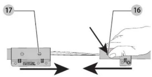
Fig. DFig. C
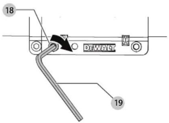
Fig. E
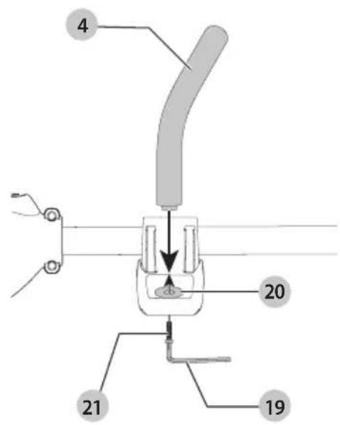
Fig. F
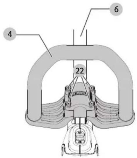
Fig. G Fig. H
natural_image
Line drawing of a person using a power tool on a tripod (no text or symbols)
Fig. K
Fig. JFig. I
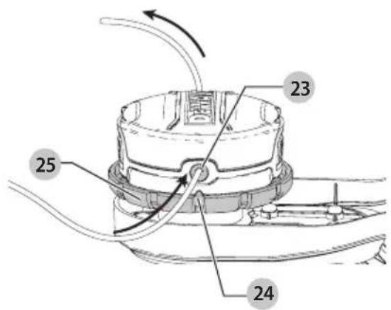
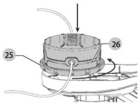
Fig. M Fig. N
Fig. L
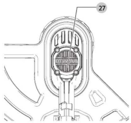
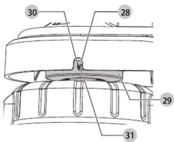
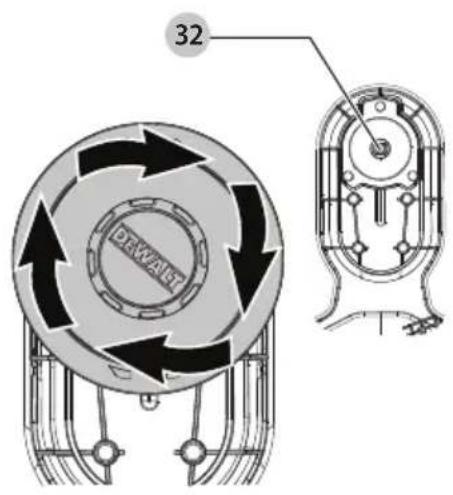
Fig. O
natural_image
Technical line drawing of a mechanical component with no visible text or symbolsFig. P
natural_image
Technical line drawing of a car body panel with internal components and directional arrow (no text or symbols)Fig. Q
18V LITHIUM SNORTRIMMER DCM561PBS, DCM561P1S
Tillykke!
natural_image
Technical line drawing of a mechanical component with no visible text or symbolsDEKRA Testing and Certification GmbH,
natural_image
Technical line drawing of a mechanical component with no visible text or symbolsYou have chosen a DEWALT tool. Years of experience, thorough product development and innovation make DEWALT one of the most reliable partners for professional power tool users.
Technical Data
| DCM561PBS DCM561P1S | |||
| Voltage V | DC | 18 18 | |
| UK & Ireland V | DC | 18 18 | |
| Type 1 1 | |||
| Battery type Li-Ion Li-Ion | |||
| Power output | W | 400 | 400 |
| RPM | 0-4600/0-6000 | 0-4600/0-6000 | |
| Cutting Swath Size | mm | 330 | 330 |
| Weight (without battery pack) | kg | 3.6 | 3.6 |
Noise values and vibration values (triax vector sum) according to EN50636-2-91:2014
| L_PA (emission sound pressure level) | dB(A) | 79.5 | 79.5 |
| L_WA (sound power level) | dB(A) | 93 | 93 |
| K (uncertainty for the given sound level) | dB(A) | 2.3 | 2.3 |
| Vibration emission value a_h = | m/s2 | 3.5 | 3.5 |
| Uncertainty K = | m/s2 | 1.5 | 1.5 |
The vibration emission level given in this information sheet has been measured in accordance with a standardised test given in EN50636 and may be used to compare one tool with another. It may be used for a preliminary assessment of exposure.

WARNING:
The declared vibration emission level represents the main applications of the tool. However if the tool is used for different applications, with different accessories or poorly maintained, the vibration emission may differ. This may significantly increase the exposure level over the total working period.
An estimation of the level of exposure to vibration should also take into account the times when the tool is switched off or when it is running but not actually doing the job. This may significantly reduce the exposure level over the total working period.
Identify additional safety measures to protect the operator from the effects of vibration such as: maintain the tool and the accessories, keep the hands warm, organisation of work patterns.
EC-Declaration of Conformity
MACHINERY DIRECTIVE
OUTDOOR NOISE DIRECTIVE

String Trimmer
DCM561PBS, DCM561P1S
DEWALT declares that these products described under
Technical Data are in compliance with:
2006/42/EC, EN60335-1:2012 + A11:2014 + A13:2017 + A1:2019
+ A14:2019 + A2:2019, EN50636-2-91:2014.
2000/14/EC, Lawn Timmer, L < 50cm, Annex VI
DEKRA Testing and Certification GmbH,
Location Certification Body,
Dinnendahlstr. 9, 44809 Bochum Germany
Notified Body number: 0158
L_NA (measured sound power level) 93 dB(A)
Uncertainty (K) = 2.3 dB(A)
L_WA (guaranteed sound power) 96 dB(A)
These products also comply with Directive 2014/30/EU and
2011/65/EU. For more information, please contact DEWALT at the following address or refer to the back of the manual.
The undersigned is responsible for compilation of the technical file and makes this declaration on behalf of DEWALT.

Markus Rompel
Director Engineering
65510, Idstein, Germany
15.06.2021
DECLARATION OF CONFORMITY
THE SUPPLY OF MACHINERY (SAFETY)
REGULATIONS 2008

String Trimmer
DCM561PBS, DCM561P1S
DEWALT declares that these products described under "technical data" are in compliance with:
The Supply of Machinery (Safety) Regulations, 2008, S.I.
2008/1597 (as amended), EN60335-1:2012 + A11:2014 +
A13:2017 + A1:2019 + A14:2019 + A2:2019, EN50636-2-91:2014.
| Batteries Chargers/Charge | Times (Minutes)*** | ||||||||||||
| Cat # V | DC | Ah Weight (kg) | DCB104 DCB107 DCB112 DCB113 DCB115 DCB116 DCB117 DCB118 DCB132 DCB119 | ||||||||||
| DCB546 | 18/54 | 6.0/2.0 | 1.08 | 60 | 270 | 170 | 140 | 90 | 80 | 40 | 60 | 90 | X |
| DCB547 | 18/54 | 9.0/3.0 | 1.46 | 75* | 420 | 270 | 220 | 135* | 110* | 60 | 75* | 135* | X |
| DCB548 | 18/54 | 12.0/4.0 | 1.46 | 120 | 540 | 350 | 300 | 180 | 150 | 80 | 120 | 180 | X |
| DCB181 | 18 | 1.5 | 0.35 | 22 | 70 | 45 | 35 | 22 | 22 | 22 | 22 | 22 | 45 |
| DCB182 | 18 | 4.0 | 0.61 | 60/40** | 185 | 120 | 100 | 60 | 60/45** | 60/40** | 60/40** | 60 | 120 |
| DCB183/B/G | 18 | 2.0 | 0.40 | 30 | 90 | 60 | 50 | 30 | 30 | 30 | 30 | 30 | 60 |
| DCB184/B/G | 18 | 5.0 | 0.62 | 75/50** | 240 | 150 | 120 | 75 | 75/60** | 75/50** | 75/50** | 75 | 150 |
| DCB185 | 18 | 1.3 | 0.35 | 22 | 60 | 40 | 30 | 22 | 22 | 22 | 22 | 22 | 40 |
| DCB187 | 18 | 3.0 | 0.54 | 45 | 140 | 90 | 70 | 45 | 45 | 45 | 45 | 45 | 90 |
| DCB189 | 18 | 4.0 | 0.54 | 60 | 185 | 120 | 100 | 60 | 60 | 60 | 60 | 60 | 120 |
| DCBP034 | 18 | 1.7 | 0.32 | 27 | 82 | 50 | 40 | 27 | 27 | 27 | 27 | 27 | 50 |
*Date code 201811475B or later.
**Date code 201536 or later.
***Battery charge times matrix provided for guidance only; charge times will vary depending on temperature and condition of batteries.
The Noise Emission in the Environment by Equipment for use Outdoors Regulations 2001, S.I. 2001/1701 (as amended), Schedule 9.
Intertek Testing & Certification Ltd
Academy Place, 1-9 Brook Street, Brentwood, Essex,
CM145NQ United Kingdom
Approved Body Number: 0359
L_WA (measured sound power level) 93 dB(A),
Uncertainty (K) = 2.3 dB(A),
L_WA (guaranteed sound power) 96 dB(A).
These products also conform to the following UK Regulations:
Electromagnetic Compatibility Regulations, 2016, S.I.2016/1091 (as amended).
The Restriction of the Use of Certain Hazardous Substances in Electrical and Electronic Equipment Regulations 2012, S.I. 2012/3032 (as amended).
For more information, please contact DEWALT at the following address or refer to the back of the manual.
The undersigned is responsible for compilation of the technical file and makes this declaration on behalf of DEWALT.

Paul Featherstone
Product Director – Outdoor Products Group
DEWALT UK,
270 Bath Road, Slough
SL1 4DX
England
15.06.2021

WARNING: To reduce the risk of injury, read the instruction manual.
Definitions: Safety Guidelines
The definitions below describe the level of severity for each signal word. Please read the manual and pay attention to these symbols.
MANGER: Indicates an imminently hazardous situation which, if not avoided, will result in death or serious injury.
WARNING: Indicates a potentially hazardous situation which, if not avoided, could result in death or serious injury.
CAUTION: Indicates a potentially hazardous situation which, if not avoided, may result in minor or moderate injury.
NOTICE: Indicates a practice not related to personal injury which, if not avoided, may result in property damage.
Dicates risk of electric shock.
Drugs risk of fire.
Safety Instructions
WARNING: When using mains-powered appliances, basic safety precautions, including the following, should always be followed to reduce the risk of fire, electric shock, personal injury and material damage.
WARNING: When using the machine the safety rules must be followed. For your own safety and
bystanders please read these instructions before operating the machine. Please keep the instructions safe for later use.
- Read all of this manual carefully before operating the appliance.
- The intended use is described in this manual. The use of any accessory or attachment or the performance of any operation with this appliance other than those recommended in this instruction manual may present a risk of personal injury.
- Retain this manual for future reference.
IMPORTANT
READ CAREFULLY BEFORE USE KEEP FOR FUTURE REFERENCE
Safe Operating Practices
Training
a) Read the instructions carefully. Be familiar with the controls and the correct use of the machine.
b) Never allow children or people unfamiliar with these instructions to use the machine. Local regulations can restrict the age of the operator.
c) Keep in mind that the operator or user is responsible for accidents or hazards occurring to other people or their property.
Preparation
a) Before use, always visually inspect the machine for damaged, missing or misplaced guards or shields.
b) Never operate the machine while people, especially children, or pets are nearby.
Operation
a) Wear eye protection and stout shoes at all times while operating the machine.
b) Avoid using the machine in bad weather conditions especially when there is a risk of lightning.
c) Use the machine only in daylight or good artificial light.
d) Never operate the machine with damaged guards or shields or without guards or shields in place.
e) Switch on the motor only when the hands and feet are away from the cutting means.
f) Always disconnect the machine from the power supply (i.e. remove the plug from the mains, remove the disabling device or removable battery)
• whenever the machine is left unattended;
• before clearing a blockage;
• before checking, cleaning or working on the machine;
• after striking a foreign object;
• whenever the machine starts vibrating abnormally.
g) Take care against injury to feet and hands from the cutting means.
h) Always ensure that the ventilation openings are kept clear of debris.
Maintenance and Storage
a) Disconnect the machine from the power supply (i.e. remove the plug from the mains, remove the disabling device or removable battery) before carrying out maintenance or cleaning work.
b) Use only the manufacturer's recommended replacement parts and accessories.
c) Inspect and maintain the machine regularly. Have the machine repaired only by an authorized repairer.
d) When not in use, store the machine out of the reach of children.
Additional Safety Instructions for Grass Trimmers
WARNING:
Cutting elements continue to switched off.
- Wear long trousers to protect your legs.
- Before using the appliance, check that your cutting path is free from sticks, stones, wire and any other obstacles.
- Only use the appliance in the upright position, with the cutting line near the ground. Never switch the appliance on in any other position.
- Move slowly when using the appliance. Be aware that freshly cut grass is damp and slippery.
- Do not work on steep slopes. Work across the face of slopes, not up and down.
- Never cross gravel paths or roads while the appliance is running.
- Never touch the cutting line while the appliance is running.
- Do not put the appliance down until the cutting line has come to a complete stand still.
- Use only the appropriate type of cutting line. Never use metal cutting line or fishing line.
- Be careful not to touch the line trimming blade.
- Keep hands and feet away from the cutting line at all times, especially when switching on the motor.
- Before using the appliance and after any impact, check for signs of wear or damage and repair as necessary.
• Take care against injury from any device fitted for trimming the filament line length. After extending new cutter line always return the machine to its normal operating position before switching on. - Close supervision is necessary when the appliance is used near children.
- This appliance is not intended for use by young or infirm persons without supervision.
• This appliance is not to be used as a toy. - Use in a dry location only. Do not allow the appliance to become wet.
- Do not immerse the appliance in water.
EngLlsh
- Do not open the body casing. There are not user-serviceable parts inside
- Do not operate the appliance in explosive atmospheres, such as in the presence of flammable liquids, gases or dust.
- When the appliance is stored or transported in a vehicle it should be placed in the boot or restrained to prevent movement following sudden changes in speed or direction.
- When not in use, the appliance should be stored in a dry, well ventilated place out of reach of children.
• Children should not have access to stored appliances.
Safety of Others
- This appliance is not intended for use by persons (including children) with reduced physical, sensory or mental capabilities, or lack of experience and knowledge, unless they have been given supervision or instruction concerning use of the appliance by a person responsible for their safety.
- Children must be supervised to ensure that they do not play with the appliance.
Residual Risks
In spite of the application of the relevant safety regulations and the implementation of safety devices, certain residual risks cannot be avoided. These are:
- Injuries caused by touching any rotating/moving parts.
- Injuries caused when changing any parts, blades or accessories.
- Injuries caused by prolonged use of a tool. When using any tool for prolonged periods ensure you take regular breaks.
- Impairment of hearing.
- Health hazards caused by breathing dust developed when using your tool (example: working with wood, especially oak, beech and MDF.)
Electrical Safety
The electric motor has been designed for one voltage only. Always check that the battery pack voltage corresponds to the voltage on the rating plate. Also make sure that the voltage of your charger corresponds to that of your mains.

Your DEWALT charger is double insulated in accordance with EN60335; therefore no earth wire is required.
If the supply cord is damaged, it must be replaced by a specially prepared cord available through the DEWALT service organisation.
Mains Plug Replacement (U.K. & Ireland Only)
If a new mains plug needs to be fitted:
• Safely dispose of the old plug.
- Connect the brown lead to the live terminal in the plug.
- Connect the blue lead to the neutral terminal.

No connection is to be made to
the earth terminal.
Follow the fitting instructions supplied with good quality plugs. Recommended fuse: 3 A.
Using an Extension Cable
An extension cord should not be used unless absolutely necessary. Use an approved extension cable suitable for the power input of your charger (see Technical Data). The minimum conductor size is 1.5 mm ^2 ; the maximum length is 30 m.
When using a cable reel, always unwind the cable completely.
SAVE THESE INSTRUCTIONS
Chargers
DEWALT chargers require no adjustment and are designed to be as easy as possible to operate.
Important Safety Instructions for All Battery Chargers
SAVE THESE INSTRUCTIONS: This manual contains important safety and operating instructions for compatible battery chargers (refer to Technical Data).
- Before using charger, read all instructions and cautionary markings on charger, battery pack, and product using battery pack.

Shock hazard. Do not allow any

We recommend the use of a
residual current device with a residual current rating of 30mA or less.

Burn hazard. To reduce the risk
of injury, charge only DEWALT rechargeable batteries.
Other types of batteries may burst causing personal injury and damage.

Children should be supervised to
ensure that they do not play with the appliance.
NOTICE:
NOTICE: Under certain conditions, with the charger plugged into the power supply, the exposed charging contacts inside the charger can be shorted by foreign material. Foreign materials of a conductive nature such as, but not limited to, steel wool, aluminum foil or any buildup of metallic particles should be kept away from charger cavities. Always unplug the charger from the power supply when there is no battery pack in the cavity. Unplug charger before attempting to clean
- DO NOT attempt to charge the battery pack with any chargers other than the ones in this manual. The charger and battery pack are specifically designed to work together.
• These chargers are not intended for any uses other than charging DEWALT rechargeable batteries. Any other uses may result in risk of fire, electric shock or electrocution.
- Do not expose charger to rain or snow.
- Pull by plug rather than cord when disconnecting charger. This will reduce risk of damage to electric plug and cord.
- Make sure that cord is located so that it will not be stepped on, tripped over, or otherwise subjected to damage or stress.
- Do not use an extension cord unless it is absolutely necessary. Use of improper extension cord could result in risk of fire, electric shock, or electrocution.
- Do not place any object on top of charger or place the charger on a soft surface that might block the ventilation slots and result in excessive internal heat. Place the charger in a position away from any heat source. The charger is ventilated through slots in the top and the bottom of the housing.
- Do not operate charger with damaged cord or plug—have them replaced immediately.
- Do not operate charger if it has received a sharp blow, been dropped, or otherwise damaged in any way. Take it to an authorised service centre.
- Do not disassemble charger; take it to an authorised service centre when service or repair is required. Incorrect reassembly may result in a risk of electric shock, electrocution or fire.
- In case of damaged power supply cord the supply cord must be replaced immediately by the manufacturer, its service agent or similar qualified person to prevent any hazard.
- Disconnect the charger from the outlet before attempting any cleaning. This will reduce the risk of electric shock. Removing the battery pack will not reduce this risk.
- NEVER attempt to connect two chargers together.
- The charger is designed to operate on standard 230V household electrical power. Do not attempt to use it on any other voltage. This does not apply to the vehicular charger.
Charging a Battery (Fig. B)
- Plug the charger into an appropriate outlet before inserting battery pack.
- Insert the battery pack 12 into the charger, making sure the battery pack is fully seated in the charger. The red (charging) light will blink repeatedly indicating that the charging process has started.
- The completion of charge will be indicated by the red light remaining ON continuously. The battery pack is fully charged and may be used at this time or left in the charger. To remove the battery pack from the charger, push the battery release button 13 on the battery pack.
NOTE: To ensure maximum performance and life of lithium-ion battery packs, charge the battery pack fully before first use.
Charger Operation
Refer to the indicators below for the charge status of the battery pack.
Charge Indicators
| Charging | — — — — — |
| Fully Charged | — — — — — |
| Hot/Cold Pack Delay* | — — — | — — |
* The red light will continue to blink, but a yellow indicator light will be illuminated during this operation. Once the battery pack has reached an appropriate temperature, the yellow light will turn off and the charger will resume the charging procedure.
The compatible charger(s) will not charge a faulty battery pack. The charger will indicate faulty battery by refusing to light or by displaying problem pack or charger blink pattern.
NOTE: This could also mean a problem with a charger.
If the charger indicates a problem, take the charger and battery pack to be tested at an authorised service centre.
Hot/Cold Pack Delay
When the charger detects a battery pack that is too hot or too cold, it automatically starts a Hot/Cold Pack Delay, suspending charging until the battery pack has reached an appropriate temperature. The charger then automatically switches to the pack charging mode. This feature ensures maximum battery pack life.
A cold battery pack will charge at a slower rate than a warm battery pack. The battery pack will charge at that slower rate throughout the entire charging cycle and will not return to maximum charge rate even if the battery pack warms.
The DCB118 charger is equipped with an internal fan designed to cool the battery pack. The fan will turn on automatically when the battery pack needs to be cooled. Never operate the charger if the fan does not operate properly or if ventilation slots are blocked. Do not permit foreign objects to enter the interior of the charger.
Electronic Protection System
XR Li-Ion tools are designed with an Electronic Protection System that will protect the battery pack against overloading, overheating or deep discharge.
The tool will automatically turn off if the Electronic Protection System engages. If this occurs, place the lithium-ion battery pack on the charger until it is fully charged.
Wall Mounting
These chargers are designed to be wall mountable or to sit upright on a table or work surface. If wall mounting, locate the charger within reach of an electrical outlet, and away from a corner or other obstructions which may impede air flow. Use the back of the charger as a template for the location of the mounting screws on the wall. Mount the charger securely using drywall screws (purchased separately) at least 25.4 mm long with a screw head diameter of 7–9 mm, screwed into wood to an optimal depth leaving approximately 5.5 mm of the screw
exposed. Align the slots on the back of the charger with the exposed screws and fully engage them in the slots.
Charger Cleaning Instructions
WARNING: Shock hazard. Disconnect the charger from the AC outlet before cleaning. Dirt and grease may be removed from the exterior of the charger using a cloth or soft non-metallic brush. Do not use water or any cleaning solutions. Never let any liquid get inside the tool; never immerse any part of the tool into a liquid.
Battery Packs
Important Safety Instructions for All Battery Packs
When ordering replacement battery packs, be sure to include catalogue number and voltage.
The battery pack is not fully charged out of the carton. Before using the battery pack and charger, read the safety instructions below. Then follow charging procedures outlined.
READ ALL INSTRUCTIONS
- Do not charge or use battery in explosive atmospheres, such as in the presence of flammable liquids, gases or dust. Inserting or removing the battery from the charger may ignite the dust or fumes.
- Never force battery pack into charger. Do not modify battery pack in any way to fit into a non-compatible charger as battery pack may rupture causing serious personal injury.
• Charge the battery packs only in DEWALT chargers.
• DO NOT splash or immerse in water or other liquids. - Do not store or use the tool and battery pack in locations where the temperature may reach or exceed 40^ (104 °F) (such as outside sheds or metal buildings in summer).
- Do not incinerate the battery pack even if it is severely damaged or is completely worn out. The battery pack can explode in a fire. Toxic fumes and materials are created when lithium-ion battery packs are burned.
- If battery contents come into contact with the skin, immediately wash area with mild soap and water. If battery liquid gets into the eye, rinse water over the open eye for 15 minutes or until irritation ceases. If medical attention is needed, the battery electrolyte is composed of a mixture of liquid organic carbonates and lithium salts.
- Contents of opened battery cells may cause respiratory irritation. Provide fresh air. If symptoms persist, seek medical attention.
WARNING: Burn hazard. Battery liquid may be flammable if exposed to spark or flame.
WARNING: Never attempt to open the battery pack for any reason. If battery pack case is cracked
or damaged, do not insert into charger. Do not crush, drop or damage battery pack. Do not use a battery pack or charger that has received a sharp blow, been dropped, run over or damaged in any way (i.e., pierced with a nail, hit with a hammer, stepped on). Electric shock or electrocution may result. Damaged battery packs should be returned to service centre for recycling.
WARNING: Fire hazard. Do not store or carry the battery pack so that metal objects can contact exposed battery terminals. For example, do not place the battery pack in aprons, pockets, tool boxes, product kit boxes, drawers, etc., with loose nails, screws, keys, etc.
CAUTION: When not in use, place tool on its side on a stable surface where it will not cause a tripping or falling hazard. Some tools with large battery packs will stand upright on the battery pack but may be easily knocked over.
Transportation
WARNING: Fire hazard. Transporting batteries can possibly cause fire if the battery terminals inadvertently come in contact with conductive materials. When transporting batteries, make sure that the battery terminals are protected and well insulated from materials that could contact them and cause a short circuit.
DEWALT batteries comply with all applicable shipping regulations as prescribed by industry and legal standards which include UN Recommendations on the Transport of Dangerous Goods; International Air Transport Association (IATA) Dangerous Goods Regulations, International Maritime Dangerous Goods (IMDG) Regulations, and the European Agreement Concerning The International Carriage of Dangerous Goods by Road (ADR). Lithium-ion cells and batteries have been tested to section 38.3 of the UN Recommendations on the Transport of Dangerous Goods Manual of Tests and Criteria.
In most instances, shipping a DEWALT battery pack will be excepted from being classified as a fully regulated Class 9 Hazardous Material. In general, only shipments containing a lithium-ion battery with an energy rating greater than 100 Watt Hours (Wh) will require being shipped as fully regulated Class 9. All lithium-ion batteries have the Watt Hour rating marked on the pack. Furthermore, due to regulation complexities, DEWALT does not recommend air shipping lithium-ion battery packs alone regardless of Watt Hour rating. Shipments of tools with batteries (combo kits) can be air shipped as excepted if the Watt Hour rating of the battery pack is no greater than 100 Whr. Regardless of whether a shipment is considered excepted or fully regulated, it is the shipper's responsibility to consult the latest regulations for packaging, labeling/marking and documentation requirements.
The information provided in this section of the manual is provided in good faith and believed to be accurate at the time
the document was created. However, no warranty, expressed or implied, is given. It is the buyer's responsibility to ensure that its activities comply with the applicable regulations.
Transporting the FLEXVOLT™ Battery
The DEWALT FLEXVOLT™ battery has two modes: Use and Transport.
Use Mode: When the FLEXVOLT™ battery stands alone or is in a DEWALT 18V product, it will operate as an 18V battery. When the FLEXVOLT™ battery is in a 54V or a 108V (two 54V batteries) product, it will operate as a 54V battery.
Transport Mode: When the cap is attached to the FLEXVOLT™ battery, the battery is in Transport mode. Keep the cap for shipping.
When in Transport mode, strings of cells are electrically disconnected within the pack resulting in 3 batteries with a lower Watt hour (Wh) rating as compared to 1 battery with a higher Watt hour rating. This increased quantity of 3 batteries with the lower Watt hour rating can exempt the pack from certain shipping regulations that are imposed upon the higher Watt hour batteries.
natural_image
Technical line drawing of a mechanical component with no visible text or symbolsFor example, the Transport Wh rating might indicate 3 x 36 Wh, meaning 3 batteries of 36 Wh each. The Use Wh rating might indicate 108 Wh (1 battery implied).
Example of Use and Transport Label Marking

Storage Recommendations
- The best storage place is one that is cool and dry away from direct sunlight and excess heat or cold. For optimum battery performance and life, store battery packs at room temperature when not in use.
- For long storage, it is recommended to store a fully charged battery pack in a cool, dry place out of the charger for optimal results.
NOTE: Battery packs should not be stored completely depleted of charge. The battery pack will need to be recharged before use.
Labels on Charger and Battery Pack
In addition to the pictographs used in this manual, the labels on the charger and the battery pack may show the following pictographs:


Read instruction manual before use.
See Technical Data for charging time.
Do not probe with conductive objects.

Do not charge damaged battery packs.

Do not expose to water.

Have defective cords replaced immediately.

Charge only between 4 °C and 40 °C.

Only for indoor use.

Discard the battery pack with due care for the environment.

Charge DEWALT battery packs only with designated DEWALT chargers. Charging battery packs other than the designated DEWALT batteries with a DEWALT charger may make them burst or lead to other dangerous situations.

Do not incinerate the battery pack.

USE (without transport cap). Example: Wh rating indicates 108 Wh (1 battery with 108 Wh).

TRANSPORT (with built-in transport cap). Example: Wh rating indicates 3 x 36 Wh (3 batteries of 36 Wh).
Battery Type
The DCM561PBS and DCM561P1S operate on an 18 volt battery pack.
These battery packs may be used: DCB181, DCB182, DCB183, DCB183B, DCB184, DCB184B, DCB185, DCB187, DCB546, DCB547, DCB548. Refer to Technical Data for more information.
Package Contents
The package contains:
1 String trimmer
1 Battery (DCM561P1S)
1 Charger (DCM561P1S)
1 Instruction manual
NOTE: Battery packs, chargers and kitboxes are not included with N models. Battery packs and chargers are not included with NT models. B models include Bluetooth® battery packs.
NOTE: The Bluetooth ^® word mark and logos are registered trademarks owned by the Bluetooth ^® , SIG, Inc. and any use of such marks by DEWALT is under license. Other trademarks and trade names are those of their respective owners.
- Check for damage to the tool, parts or accessories which may have occurred during transport.
• Take the time to thoroughly read and understand this manual prior to operation.
Markings on Tool
The following pictograms are shown on the tool:


Read instruction manual before use.
Wear ear protection.
Wear eye protection.

Switch the tool off. Before performing any maintenance on the tool, remove the battery from the tool.


Keep bystanders away.

Do not expose the tool to rain or high humidity or leave outdoors while it is raining.
Date Code Position (Fig. A)
The date code 36, which also includes the year of manufacture, is printed into the housing.
Example:
2022 XX XX
Year of Manufacture
Description (Fig. A)

Never modify the power tool or any part of it. Damage or personal injury could result.
1 Variable speed trigger
2 Lock-off lever
3 Speed control switch
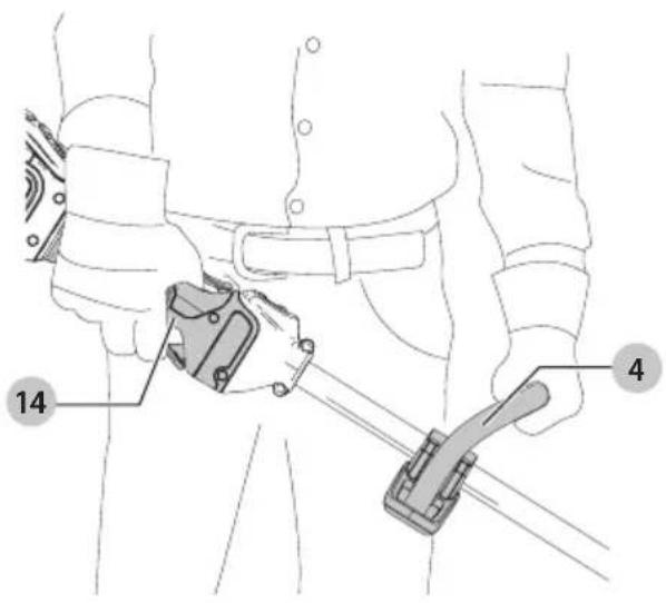
4 Auxiliary handle
5 Motor housing
6 Upper trimmer pole
7 Lower trimmer pole
8 Pole bracket
9 Guard
10 Spool housing
11 Battery housing
12 Battery pack
13 Battery release button
14 Main handle
Intended Use
Your string trimmer is designed for professional trimming applications.
DO NOT use under wet conditions or in the presence of flammable liquids or gases.
This is not an edger and is not intended to be used for edging.
Your string trimmer is a professional appliance.
DO NOT let children come into contact with the tool.
Supervision is required when inexperienced operators use this tool.
- Young children and the infirm. This appliance is not intended for use by young children or infirm persons without supervision.
- This product is not intended for use by persons (including children) suffering from diminished physical, sensory or mental abilities; lack of experience, knowledge or skills unless they are supervised by a person responsible for their safety. Children should never be left alone with this product.
ASSEMBLY AND ADJUSTMENTS

To reduce the risk of serious
personal injury, turn appliance off and remove battery before making any adjustments or removing/installing attachments or accessories. An accidental start-up can cause injury.

Use only DEWALT battery packs
and chargers.

Never operate appliance
without guard firmly in place. Damage or personal injury could result.
Inserting and Removing the Battery Pack (Fig. B)
NOTE: Make sure your battery pack 12 is fully charged.

Before removing or installing
battery, make certain the lock-off lever is not engaged to prevent trigger actuation.
To install the battery pack into the tool handle
- Align the battery pack 12 with the rails inside the tool's handle.
- Slide it into the handle until the battery pack is firmly seated in the tool and ensure you hear the lock snap into place.
To remove the battery pack from the tool
- Press the release button 13 and firmly pull the battery pack out of the tool handle.
- Insert battery pack into the charger as described in the charger section of this manual.
Fuel Gauge Battery Packs (Fig. B)
Some DEWALT battery packs include a fuel gauge which consists of three green LED lights that indicate the level of charge remaining in the battery pack.
To actuate the fuel gauge, press and hold the fuel gauge button 15. A combination of the three green LED lights will illuminate designating the level of charge left. When the level of charge in the battery is below the usable limit, the fuel gauge will not illuminate and the battery will need to be recharged.
NOTE: The fuel gauge is only an indication of the charge left on the battery pack. It does not indicate tool functionality and is
subject to variation based on product components, temperature and end-user application.
Assembling the Pole (Fig. C, D)
- To assemble the pole, line up the upper trimmer pole 6 and the lower trimmer pole 7 as shown in Figure C. Press down the latching button 16 and slide the upper pole into the lower pole. Ensure the latching button engages the latch hole 17.
- Secure the poles by tightening the middle bolt 18 with the supplied hex wrench 19 as shown in Figure D.
Attaching the Auxiliary Handle (Fig. E)
- Slide the auxiliary handle 4 into the top hole of the handle base 20.
- Hold the auxiliary handle in place and thread the handle bolt 21 into the handle from the bottom of the handle base.
- Tighten the handle bolt with the supplied hex wrench 19. Ensure the handle is securely attached.
- Repeat for the other side of the auxiliary handle.
Adjusting Auxiliary Handle (Fig. F)
The trimmer comes fully assembled. The auxiliary handle 4 is positioned to maximize balance. However, if adjustment is necessary, loosen the four bolts 22 with a hex wrench and slide the auxiliary handle up or down the upper trimmer pole 6.
OPERATION
Instructions for Use
WARNING: Always observe the safety instructions and applicable regulations.
WARNING: To reduce the risk of serious personal injury, turn appliance off and remove battery before making any adjustments or removing/installing attachments or accessories. An accidental start-up can cause injury.
WARNING: Always use proper eye protection that conforms to ANSI Z87.1 (CAN/CSA Z94.3) while operating this appliance.
CAUTION: Before you begin trimming, only use the appropriate type of cutting line.
CAUTION: Inspect area to be trimmed and remove any wire, cord, or string-like objects which could become entangled in the rotating line or spool. Be particularly careful to avoid any wire which might be bent outwardly into the path of the appliance, such as barbs at the base of a chain link fence.
Proper Hand Position (Fig. G)
WARNING: To reduce the risk of serious personal injury, ALWAYS use proper hand position as shown.
WARNING: To reduce the risk of serious personal injury, ALWAYS hold securely in anticipation of a sudden reaction.
Proper hand position requires one hand on the main handle 14 and one hand on the auxiliary handle 4.
Switching Trimmer On and Off (Fig. A)
To turn the appliance on, push the lock off tab 37 forward, squeeze the lock-off lever 2, and then squeeze the variable speed trigger 1.
To turn the appliance off, release the variable speed trigger, the lock-off lever, and tab.
WARNING: Never attempt to lock the trigger in the on position.
Speed Control Switch (Fig. A)
This string trimmer gives you the choice to operate at a more efficient speed to extend the runtime for larger jobs, or accelerate the trimmer speed for high-performance cutting. To extend runtime, push the speed control switch 3 forward toward the auxiliary handle 4 into the "LO" position. This mode is best for larger projects that require more time to complete. To accelerate the trimmer, pull the speed control switch back toward the battery housing 11 into the "HI" position. This mode is best to cut through heavier growth and for applications that need higher RPM.
NOTE: When in "HI" mode, runtime will be decreased as compared to when trimmer is in "LO" mode.
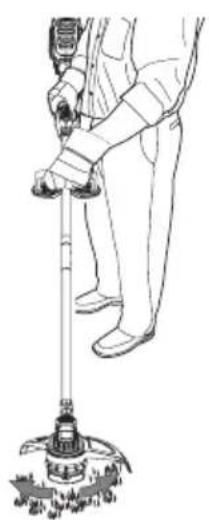
Trimming (Fig. H, I)
With the trimmer on, angle it and swing side to side as shown in Figure H.
Maintain a minimum distance of 610 mm between the guard and your feet as shown in Figure I.
WARNING: Keep the rotating string roughly parallel with the ground (tilted no more than 30 degrees). This trimmer is not an edger. DO NOT TILT the trimmer so that the string is spinning near a right angle to the ground. Flying debris can cause serious injury.
Bump Feed Trimmer Line Feed
Your trimmer uses 2.032 mm diameter nylon line. Cutting line will wear faster and require more feeding if the cutting is done along sidewalks or other abrasive surfaces or heavier weeds are being cut.
As you use the trimmer, the string will get shorter due to wear. Gently bump the trimmer on the ground while running at normal speed and the line will feed.
NOTE: Extending nylon line beyond the 330 mm swath will negatively affect performance, runtime, and the life of the trimmer due to potential of damaging motor. Doing so may void the warranty.
Helpful Cutting Tips
- Use the tip of the string to do the cutting; do not force string head into uncut grass.
- Wire and picket fences cause extra string wear, even breakage. Stone and brick walls, curbs, and wood may wear string rapidly.
- Do not allow spool cap to drag on ground or other surfaces.
- In long growth, cut from the top down and do not exceed 304.8 mm high.
- Keep trimmer tilted toward the area being cut; this is the best cutting area.
- The trimmer cuts when passing the unit from the left to right. This will avoid throwing debris at the operator.
- Avoid trees and shrubs. Tree bark, wood moldings, siding, and fence posts can easily be damaged by the string.
Reloading the Cutting Line (Fig. J, K)
WARNING: To reduce the risk of serious personal injury, turn appliance off and remove battery before making any adjustments or removing/installing attachments or accessories. An accidental start-up can cause injury.
CAUTION: Use only DEWALT replacement spools and line. Using any other manufacturer's line can reduce performance, damage the trimmer or cause personal injury. Your trimmer uses 2.032 mm diameter line, however a 02.413 mm line may be used as long as it is spiral-shaped with smooth, round edges, but may reduce runtime of the trimmer.
CAUTION: To avoid appliance damage, if the cutting line protrudes beyond the trimming blade, cut it off so that it just reaches the blade.
Use only DEWALT replacement line.
- Remove battery.
- Cut a max of 8 m length of trimmer line.
- Align spool housing eyelets 23 with the arrow 24 on the spool head 25 as shown in Figure J.
- Thread one end of the trimmer line through an eyelet. Guide the line through to the second eyelet and continue to pull the line through until there are equal lengths of string on each side of the spool housing as shown in Figure J.
- Secure the spool cap 26 from moving with one hand. Using your other hand, wind the string onto the spool by rotating
the spool head 25 anti-clockwise as shown in Figure K. Continue winding until 127 mm of string remain on each side of the spool housing.
Replacement Accessories
WARNING: To reduce the risk of serious personal injury, turn appliance off and remove battery before making any adjustments or removing/installing attachments or accessories. An accidental start-up can cause injury.
WARNING: The use of any accessory not recommended by DEWALT for use with this appliance could be hazardous.
WARNING: Do not use any blades, or any accessory or attachment other than those recommended by DEWALT on this trimmer. Serious injury or product damage may result.
Use DEWALT replacement line Model No. DWO1DT801 or DWO1DT802.
- When replacing the line, use only 2.032 mm diameter line (Model No. DWO1DT801 or DWO1DT802) is recommended. For optimal performance, do not use 2.413 mm line. Other sized may degrade performance and cause damage to the trimmer.
MAINTENANCE (FIG. L)
Your DEWALT power tool has been designed to operate over a long period of time with a minimum of maintenance. Continuous satisfactory operation depends upon proper tool care and regular cleaning.
WARNING: To reduce the risk of serious personal injury, turn appliance off and remove battery before making any adjustments or removing/installing attachments or accessories. An accidental start-up can cause injury.
- Keep the air intake slots 27 shown in Figure L, clean to avoid overheating.
- Your trimmer line can dry out over time. To keep your line in top condition, store spare line in a plastic, sealable bag with a tablespoon of water.
- Plastic parts may be cleaned by using a mild soap and a damp rag.
- The line cutter on the edge of the guard can dull over time. It is recommended you periodically touch-up the sharpness of the blade with a file.
The charger and battery pack are not serviceable.

Lubrication
Your power tool requires no additional lubrication.

Cleaning
WARNING: Blow dirt and dust out of the main housing with dry air as often as dirt is seen collecting in and around the air vents. Wear approved eye protection and approved dust mask when performing this procedure.
WARNING: Never use solvents or other harsh chemicals for cleaning the non-metallic parts of the tool. These chemicals may weaken the materials used in these parts. Use a cloth dampened only with water and mild soap. Never let any liquid get inside the tool; never immerse any part of the tool into a liquid.
Replacing Spool Housing (Fig. M, N)
- Rotate the spool housing 10 until the hole 28 in the spindle 29 lines up with notch 30 in the guard 9. A third hole in the motor housing 31 will be visible as shown in Figure M. Insert screwdriver through each all three holes to prevent the spool housing from turning.
- Turn the spool housing clockwise as shown in Figure N.
- Insert a screwdriver back through the three holes 28, 30, and 31 and thread the new spool housing anti-clockwise and securely tighten onto the bolt 32 protruding from the trimmer.
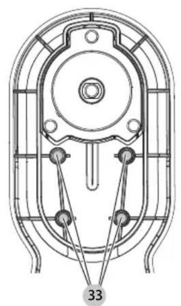
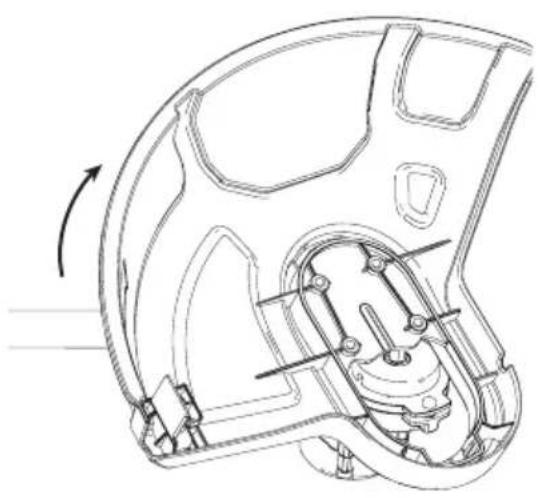
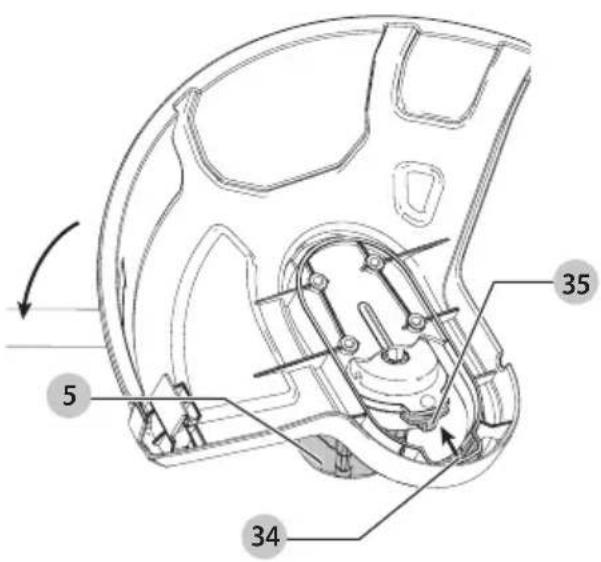
Replacing Guard (Fig. 0–Q)
WARNING: Never operate appliance without guard firmly in place.
- Remove the spool housing as described in the Replacing Spool Housing section.
- Remove the 4 guard screws 33 shown in Figure O.
- Lift the guard off at an angle as shown in Figure P.
- To attached a new guard, slide the tab 34 of the new guard under the lip 35 of the motor housing 5, then lower the back of the guard into place as shown in Figure Q.
- Replace and securely tighten the 4 guard screws 33.
- Replace the spool housing as described in the Replacing Spool Housing section.
Optional Accessories
WARNING: Since accessories, other than those offered by DEWALT, have not been tested with this product, use of such accessories with this tool could be hazardous. To reduce the risk of injury, only DEWALT recommended accessories should be used with this product.
Consult your dealer for further information on the appropriate accessories.
Protecting the Environment

Separate collection. Products and batteries marked with this symbol must not be disposed of with normal household waste.
Products and batteries contain materials that can be recovered or recycled reducing the demand for raw materials. Please recycle electrical products and batteries according to local provisions. Further information is available at www.2helpU.com.
Rechargeable Battery Pack
This long life battery pack must be recharged when it fails to produce sufficient power on jobs which were easily done before. At the end of its technical life, discard it with due care for our environment:
- Run the battery pack down completely, then remove it from the tool.
- Li-lon cells are recyclable. Take them to your dealer or a local recycling station. The collected battery packs will be recycled or disposed of properly.
TROUBLESHOOTING
| Problem Solution | |
| Unit will not start. Check battery installation.Check battery charging requirements.Check that lock off is fully pulled back prior to moving main trigger. | |
| Unit shuts down in use. Charge battery.Clear debris around spool.Reduce/limit swath to 330 mm MAX.Reinstall guard if it has been removed. | |
| Battery won't charge. | Insert battery into charger until red charging light illuminates. Charge up to 8 hours if battery is totally drained.Plug charger into a working outlet. Refer to Charger Operation for more details.Check current at receptacle by plugging an appliance.Check to see if receptacle is connected to a light switch which turns power off when you turn out the lights.Move charger and appliance to a surrounding air temperature of above 4 °C or below 40 °C. |
| Appliance runs slowly. Fully depress the variable speed trigger. The level of trigger depression affects speed.If appliance still runs slowly, remove battery from appliance.Check that the spool housing can rotate freely. Carefully clean it if necessary.Check that the cutting line does not protrude more than approximately 122 mm from the spool. If it does, cut it off so that it just reaches the line trimming blade. | |
| Trimmer is vibrating. Make sure both cutting lines are the same length.Check to see if the spool is properly wound. If spool is broken then replace spool. | |
DESBROZADORA 18V LITIO DCM561PBS, DCM561P1S
¡Enhorabuena!
natural_image
Technical line drawing of a mechanical component with no visible text or symbolsnatural_image
Technical line drawing of a device with no visible text or symbolsBatterie rechargeable
Prassi operative sicure
Formazione
natural_image
Technical line drawing of a device casing with mounting holes and a handle (no text or symbols)MAARSCHUWING: Brandgevaar.
natural_image
Technical line drawing of a device casing with mounting holes and a tray (no text or symbols)WAARSCHUWING: Beperk
WAARSCHUWING: Controleer
WAARSCHUWING: Houd u
WAARSCHUWING: Beperk
VAARSCHUWING: Probeer
WAARSCHUWING: Beperk
DEKRA Testing and Certification GmbH,
Location Certification Body,
Dinnendahlstr. 9, 44809 Bochum Germany
Godkjenningsinstans nr. (Notified Body number):0158
L_WA (målt lydeffekt) 93 dB(A)
Usikkerhet (K) = 2,3 dB(A)
L_WA (garantert lydeffekt) 96 dB(A)
natural_image
Technical line drawing of a device casing with mounting holes and a handle (no text or symbols)VEDLIKEHOLD (FIG. L)
Director de Engenharia
natural_image
Technical line drawing of a device casing with mounting holes and a handle (no text or symbols)DEKRA Testing and Certification GmbH,
Location Certification Body,
Dinnendahlstr. 9, 44809 Bochum Germany
Ilmoitetun laitoksen numero: 0158
65510, Idstein, Germany
15.11.2017

natural_image
Technical line drawing of a device casing with mounting holes and a handle (no text or symbols)DEKRA Testing and Certification GmbH,
Location Certification Body,
Dinnendahlstr. 9, 44809 Bochum Germany
natural_image
Technical line drawing of a mechanical component with no visible text or symbolsnatural_image
Technical line drawing of a mechanical component with no visible text or symbolsDEKRA Testing and Certification GmbH,
Markus Rompel