D27105 - Saw DEWALT - Free user manual and instructions
Find the device manual for free D27105 DEWALT in PDF.

User questions about D27105 DEWALT
0 question about this device. Answer the ones you know or ask your own.
Ask a new question about this device
Download the instructions for your Saw in PDF format for free! Find your manual D27105 - DEWALT and take your electronic device back in hand. On this page are published all the documents necessary for the use of your device. D27105 by DEWALT.
USER MANUAL D27105 DEWALT
text_image
Technical diagram of a mechanical device with numbered parts for identificationA1
text_image
Technical diagram of a robotic device with numbered parts labeled for identification.A2
text_image
21 20 1922 23 17 18A3
natural_image
Technical line drawing of a mechanical bracket component (no text or symbols)A4
text_image
34 3536 39 3837 31 33 32A5
natural_image
Technical line drawing of a mechanical support structure with four legs and a horizontal beam, labeled '40' (no text or symbols beyond label)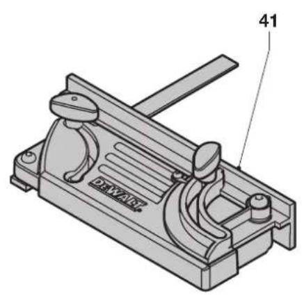
natural_image
Technical line drawing of a mechanical clamp or lever device (no text or symbols)A6 A7
text_image
42 32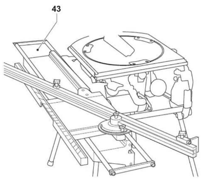
natural_image
Technical line drawing of a mechanical assembly with no visible text or symbolsA8
A9
natural_image
Technical illustration of a coiled pipe joint with a separate curved structure (no text or symbols)A10

text_image
53 52 54 55 16 51B
text_image
59 58 15 56 57 C1C1
text_image
58 5657 15 C2 59C2
text_image
15 59 C3C3
natural_image
Technical line drawing of a mechanical assembly with gears and shafts (no text or symbols)C4
text_image
60 14 61 62D
text_image
63 6665 64E
text_image
19 2 F1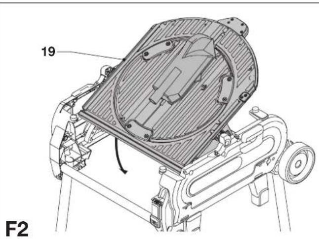
text_image
19 F2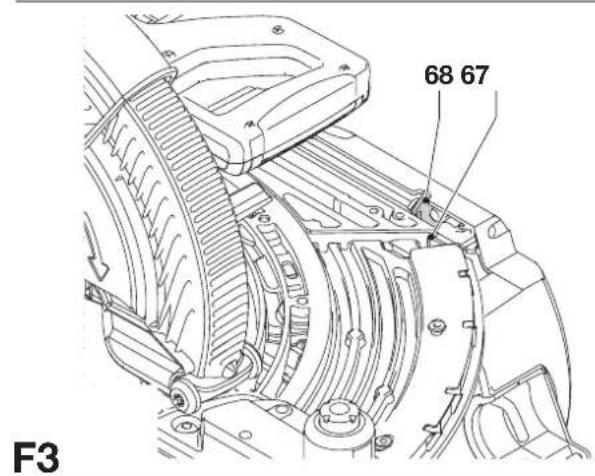
text_image
68 67 F3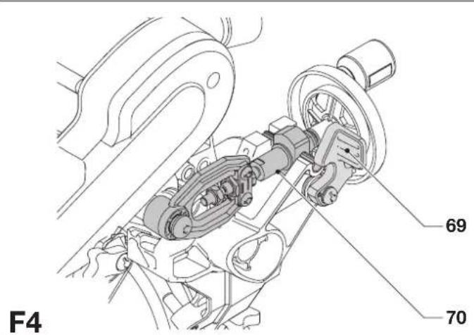
text_image
F4 69 70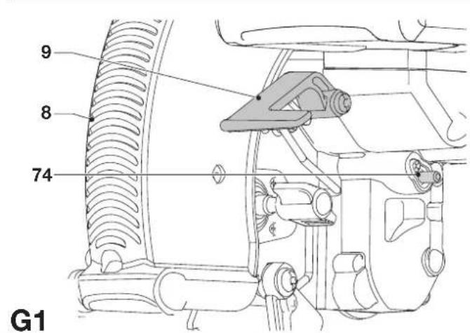
text_image
9 8 74 G1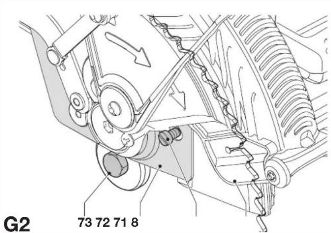
text_image
G2 73 72 71 8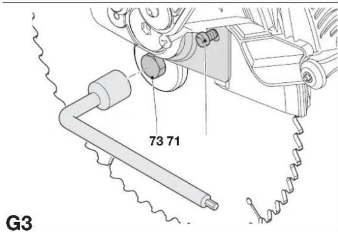
text_image
73 71 G3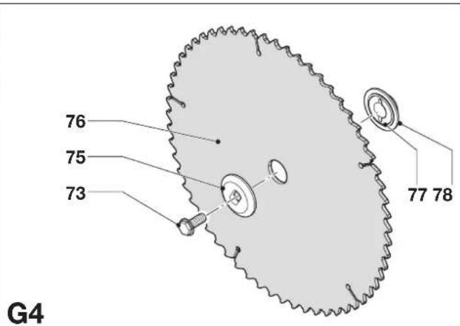
text_image
76 75 73 77 78 G4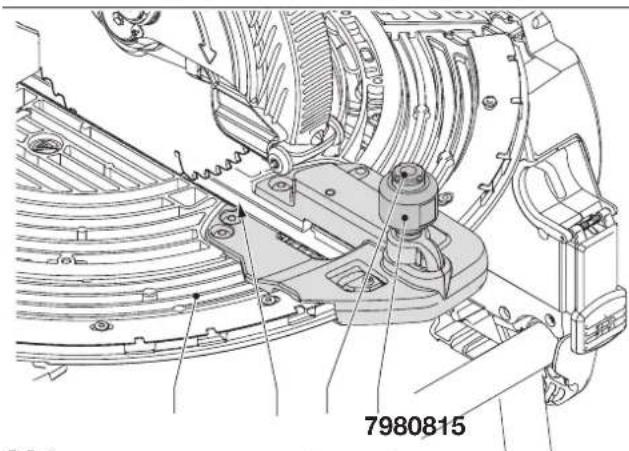
text_image
7980815H1
natural_image
Technical line drawing of a mechanical assembly with no visible text or symbolsH2
natural_image
Technical line drawing of a mechanical assembly with no visible text or symbolsH3
text_image
84 8685H4
natural_image
Technical line drawing of a mechanical assembly with labeled component '17' (no readable text or symbols beyond label)11
text_image
7682 8112
text_image
89 8788 9013
text_image
92 7 91J
text_image
94 95 88 88 K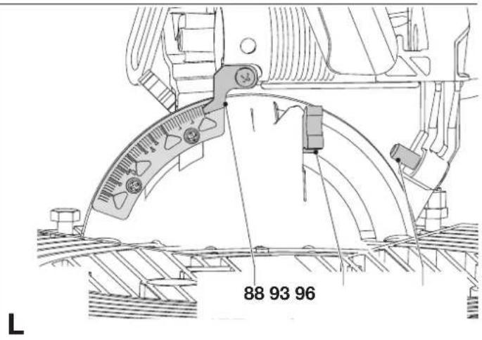
text_image
88 93 96 L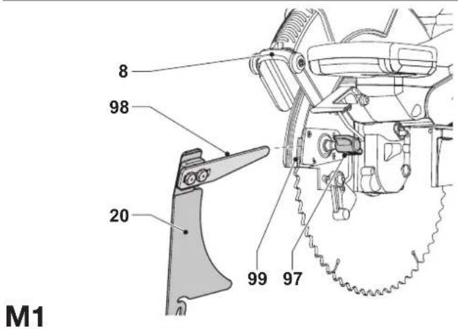
text_image
M1 8 98 20 99 97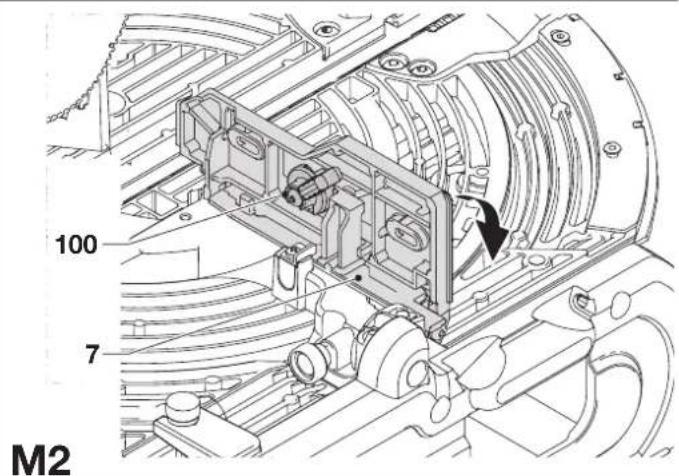
text_image
100 7 M2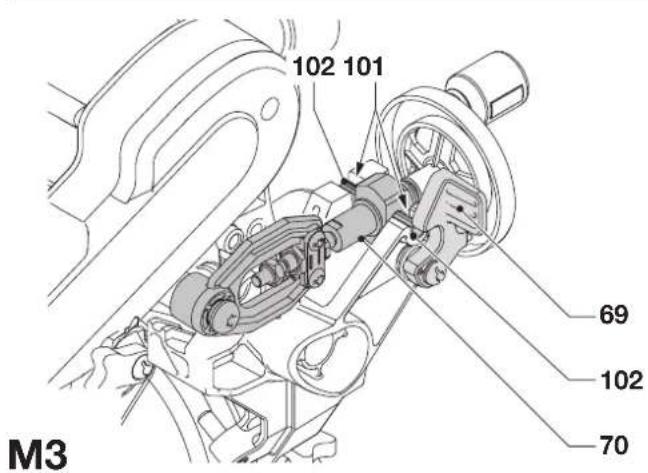
text_image
102 101 69 102 70 M3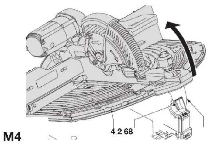
text_image
M4 4 2 68
text_image
68 67 M5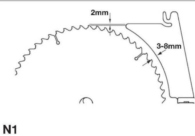
text_image
2mm 3-8mm N1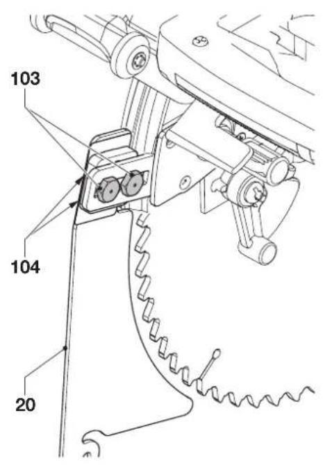
text_image
103 104 20N2
text_image
105 20 21 106 O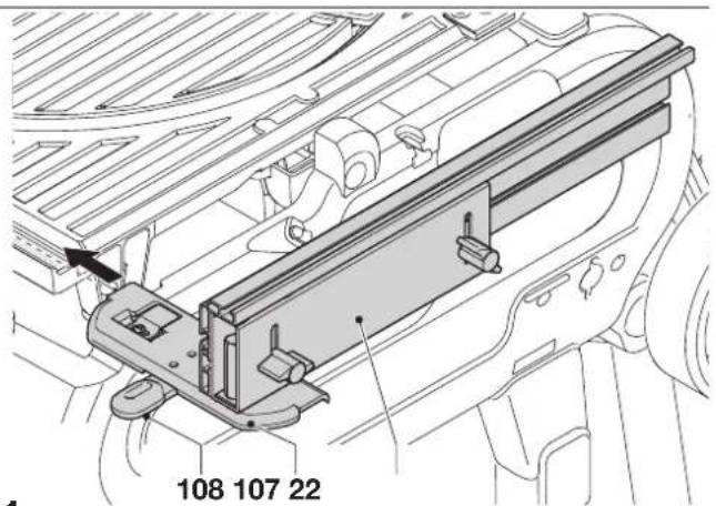
text_image
108 107 22P1

text_image
110 109P2
text_image
112 111 P3P3
text_image
114 109 113P4
text_image
114 109 113P5
text_image
41 Q1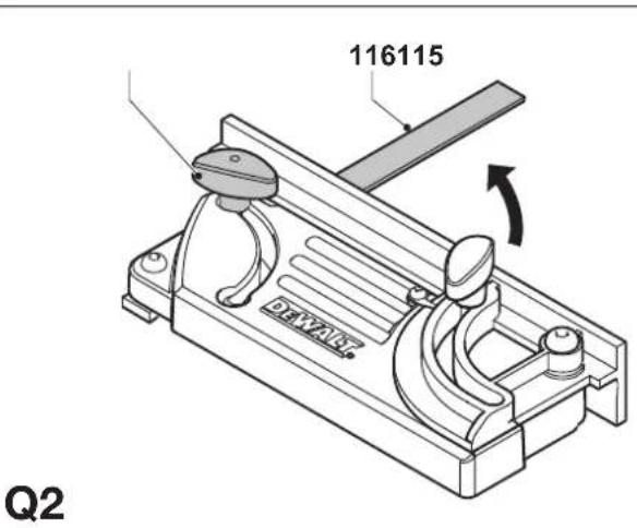
text_image
116115 Q2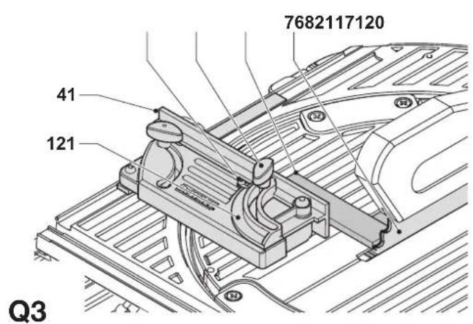
text_image
7682117120 41 121 Q3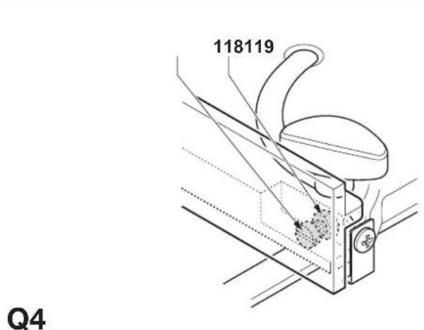
text_image
118119 Q4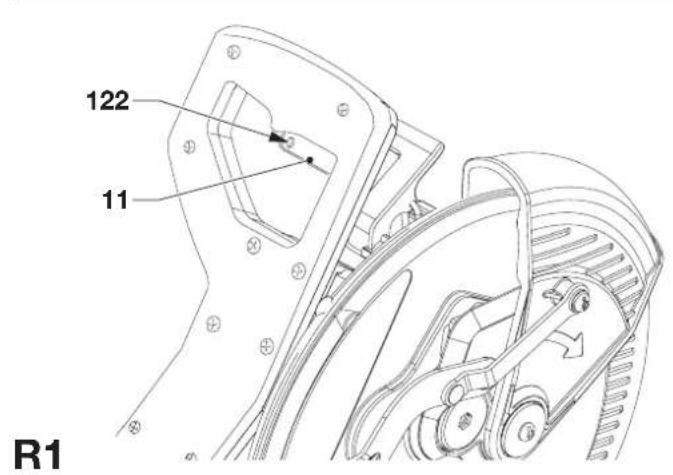
text_image
122 11 R1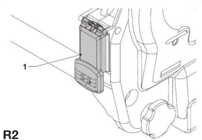
text_image
1 R2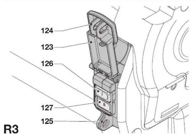
text_image
124 123 126 127 125 R3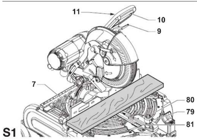
text_image
S1 7 11 10 9 80 79 81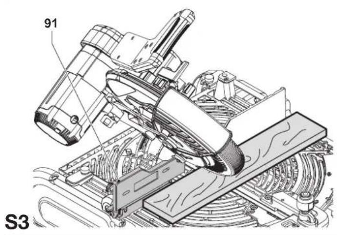
text_image
91 S3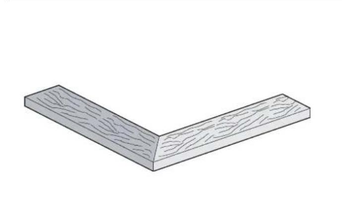
natural_image
Isometric view of a wooden L-shaped beam with visible grain patterns (no text or symbols)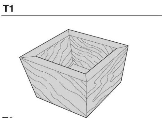
natural_image
Isometric line drawing of a square wooden box with visible grain patterns (no text or symbols)
text_image
T3
text_image
79 80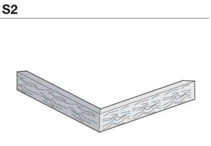
natural_image
Isometric view of a wooden L-shaped block with visible grain patterns (no text or symbols)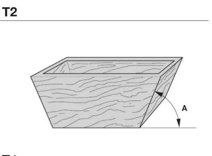
text_image
T2 A T1
text_image
T4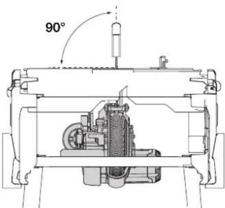 | 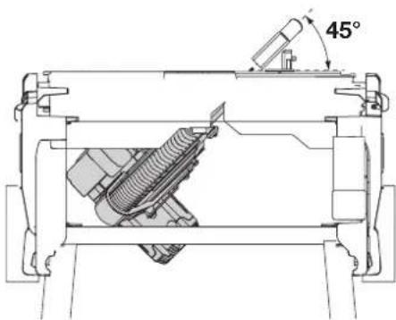 | |
| U1 U2 | ||
| [U3] | 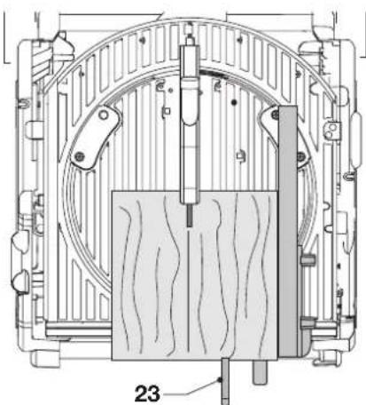 | 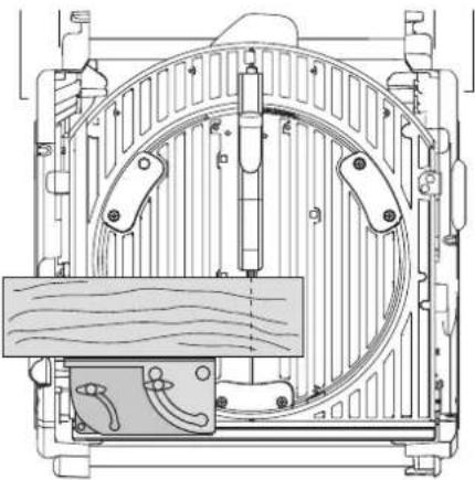 |
| V1 | ||
 |  | |
| V2 | W1 | |
 |  | |
| W2 | X1 | |
text_image
132 135 134 133 X2
text_image
X3 136133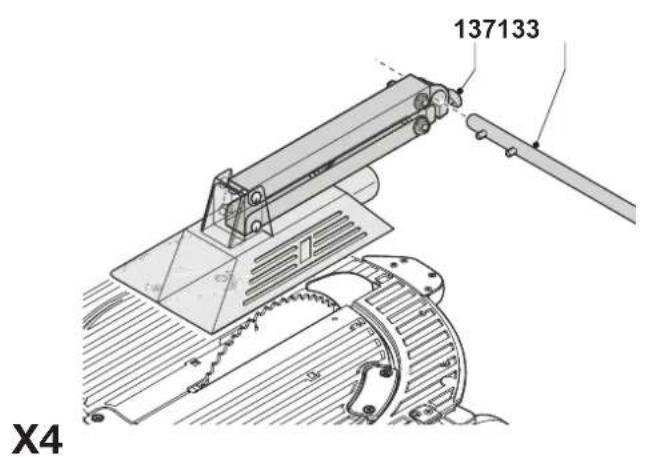
text_image
137133 X4
natural_image
Technical line drawing of a mechanical assembly with gears and shafts (no text or symbols)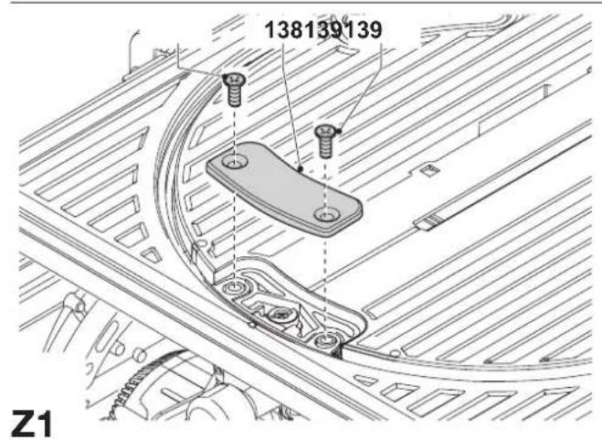
text_image
138139139 Z1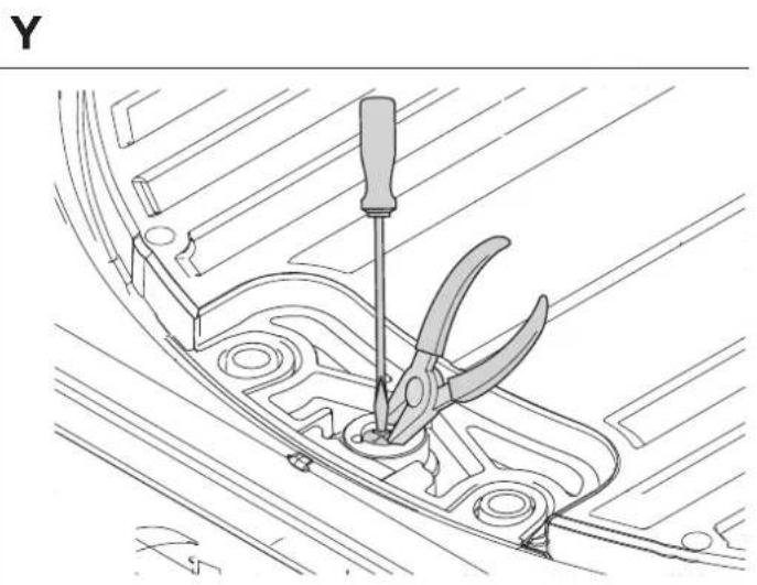
natural_image
Technical line drawing of a mechanical component with a screwdriver inserted, no text or symbols present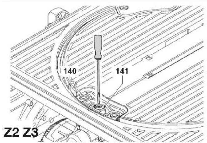
text_image
140 141 Z2 Z3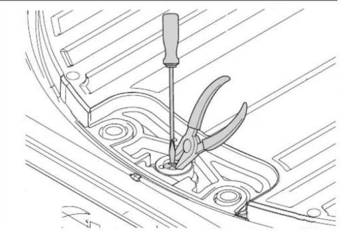
natural_image
Technical line drawing of a mechanical component with a screwdriver inserted, showing no text or symbolsFLIP-OVER-SAV D27105
Tillykke!
You have chosen a DEWALT tool. Years of experience, thorough product development and innovation make DEWALT one of the most reliable partners for professional power tool users.
Technical data
| D27105 | |
| Voltage V 230 | |
| Power input W 2,000 | |
| Power output W 1,700 | |
| Max. blade speed min | -1 4,100 |
| Blade diameter mm 300 - 305 | |
| Blade bore mm 30 | |
| Blade body thickness mm 2.1 - 2.2 | |
| Riving knife thickness mm 2.5 | |
| Automatic blade brake time s < 10 | |
| Weight kg 42 | |
Cutting capacities
| Mitre saw mode | ||
| Mitre (max. positions) left 48° | right 48° | |
| Bevel (max. positions) left 48° | right 2° | |
| Max. crosscut capacity at 90° mm 205 | ||
| Max. mitre cut capacity at 45° mm 160 | ||
| Max. depth of cut 90° | mm 155 | |
| Max. depth of bevel cut 45° | mm 110 | |
| Max. depth of cut at 45° bevel, 45° mitre | mm 100 | |
| Saw bench mode | ||
| Max. ripping capacity left/right mm 120/320 | ||
| Depth of cut at 90° | mm 81 | |
| Depth of cut at 45° | mm 56 | |
| Fuses: | ||
| Europe | 230 V tools | 10 Amperes, mains |
| U.K. & Ireland | 230 V tools | 13 Amperes, in plugs |
The following symbols are used throughout this manual:

Denotes risk of personal injury, loss of life or damage to the tool in case of non-observance of the instructions in this manual.

Denotes risk of electric shock.

Sharp edges.
EC-Declaration of conformity

D27105
DEWALT declares that these power tools have been designed in compliance with: 98/37/EEC, 89/336/EEC, 73/23/EEC, EN 61029-1, EN 61029-2-11, EN 55014, EN 55014-2, EN 61000-3-2 & EN 61000-3-3.
For more information, please contact DEWALT at the address below or refer to the back of the manual.
Level of sound pressure according to 86/188/EEC & 98/37/EEC, measured according to EN 61029-2-11:
| D27105 | |||
| L_pa | (sound pressure) | dB(A)* | 89.6 |
| L_wq | (acoustic power) | dB(A) | 100.6 |
* at the operator's ear

Take appropriate measures for the protection of hearing.
Weighted root mean square acceleration value according to EN 61029-2-11:
| D27105 |
| < 2,5 m/s ^2 |
Director Engineering and Product Development
Horst Großmann

text_image
X. JopmanD-65510, Idstein, Germany
Safety instructions
When using stationary power tools, always observe the safety regulations applicable in your country to reduce the risk of fire, electric shock and personal injury.
Read all of this manual carefully before operating the tool.
Save this manual for future reference.
General
1 Keep work area clean
Cluttered areas and benches can cause accidents.
2 Consider work area environment
Do not expose the tool to rain. Do not use the tool in damp or wet conditions. Keep the work area well lit (250 - 300 Lux). Do not use the tool where there is a risk of causing fire or explosion, e.g. in the presence of flammable liquids and gases.
3 Keep children away
Do not allow children, visitors or animals to come near the work area or to touch the tool or the mains cable.
4 Dress properly
Do not wear loose clothing or jewellery, as these can be caught in moving parts. Wear protective hair covering to keep long hair out of the way. When working outdoors, preferably wear suitable gloves and non-slip footwear.
5 Personal protection
Always use safety glasses. Use a face or dust mask whenever the operations may produce dust or flying particles. If these particles might be considerably hot, also wear a heat-resistant apron. Wear ear protection at all times. Wear a safety helmet at all times.
6 Guard against electric shock
Prevent body contact with earthed or surfaces (e.g. pipes, radiators, cookers and refrigerators). When using the tool under extreme conditions (e.g. high humidity, when metal swarf is being produced, etc.), electric safety can be improved by inserting an isolating transformer or a (FI) earth-leakage circuit-breaker.
7 Do not overreach
Keep proper footing and balance at all times.
8 Stay alert
Watch what you are doing. Use common sense. Do not operate the tool when you are tired.
9 Secure workpiece
Use clamps or a vice to hold the workpiece. It is safer and it frees both hands to operate the tool.
10 Connect dust extraction equipment
If devices are provided for the connection of dust extraction and collection facilities, ensure that these are connected and properly used.
11 Remove adjusting keys and wrenches
Always check that adjusting keys and wrenches are removed from the tool before operating the tool.
12 Extension cables
Before use, inspect the extension cable and replace if damaged. When using the tool outdoors, only use extension cables intended for outdoor use and marked accordingly.
13 Use appropriate tool
The intended use is described in this instruction manual. Do not force small tools or attachments to do the job of a heavy-duty tool. The tool will do the job better and safer at the rate for which it was intended. Do not force the tool.
Warning! The use of any accessory or attachment or performance of any operation with this tool other than those recommended in this instruction manual may present a risk of personal injury.
14 Check for damaged parts
Before use, carefully check the tool and mains cable for damage. Check for misalignment and seizure of moving parts, breakage of parts, damage to guards and switches and any other conditions that may affect its operation.
Ensure that the tool will operate properly and perform its intended function. Do not use the tool if any part is damaged or defective.
Do not use the tool if the switch does not turn it on and off. Have any damaged or defective parts replaced by an authorised DEWALT repair agent. Never attempt any repairs yourself.
15 Unplug tool
Switch off and wait for the tool to come to a complete standstill before leaving it unattended. Unplug the tool when not in use, before changing any parts of the tools, accessories or attachments and before servicing.
16 Avoid unintentional starting
Be sure that the tool is switched off before plugging in.
17 Do not abuse cord
Never pull the cord to disconnect from the socket. Keep the cord away from heat, oil and sharp edges.
18 Store idle tools
When not in use, tools must be stored in a dry place and locked up securely, out of reach of children.
19 Maintain tools with care
Keep the tools in good condition and clean for better and safer performance. Follow the instructions for maintenance and changing accessories. Keep all handles and switches dry, clean and free from oil and grease.
20 Repairs
This tool is in accordance with the relevant safety regulations.
Have your tool repaired by an authorised DEWALT repair agent.
Repairs should only be carried out by qualified persons using original spare parts; otherwise this may result in considerable danger to the user.
Additional safety rules for mitre saws
- Make sure all locking knobs and clamp handles are tight before starting any operation.
- Do not operate the machine without the guard in position, or if the guard does not function or is not maintained properly.
- Never place either hand in the blade area when the saw is connected to the electrical power source.
- Never attempt to stop a machine in motion rapidly by jamming a tool or other means against the blade; serious accidents can be caused unintentionally in this way.
- Before using any accessory consult the instruction manual. The improper use of an accessory can cause damage.
- Select the correct blade for the material to be cut.
- Observe the maximum speed marked on the saw blade.
- Use a holder or wear gloves when handling a saw blade.
- Make sure that the blade rotates in the correct direction. Keep the blade sharp.
- The max. allowable speed of the saw blade must always be equal to or greater than the no-load speed of the tool specified on the nameplate.
- Do not use saw blades that do not conform to the dimensions stated in the technical data. Do not use any spacers to make a blade fit onto the spindle. Use only the blades specified in this manual, complying with EN 847-1.
- Consider applying specially designed noise-reduction blades.
- Do not use HSS blades.
- Do not use cracked or damaged saw blades.
- Do not use any abrasive discs.
- After completing the cut, release the switch and wait for the saw blade to come to a complete stillstand before returning the head to its upper rest position.
- Ensure that the arm is securely fixed when performing bevel cuts.
- Do not wedge anything against the fan to hold the motor shaft.
- The blade guard on your saw will automatically raise when the arm is brought down; it will lower over the blade when the arm is raised. The guard can be raised by hand when installing or removing saw blades or for inspection of the saw. Never raise the blade guard manually unless the saw is switched off.
- Keep the surrounding area of the machine well maintained and free of loose materials, e.g. chips and cut-offs.
- Check periodically that the motor air slots are clean and free of chips.
- Disconnect the machine from the mains before carrying out any maintenance work or when changing the blade.
- Never perform any cleaning or maintenance work when the machine is still running and the head is not in the rest position.
- The front section of the guard is louvred for visibility while cutting. Although the louvres dramatically reduce flying debris, there are openings in the guard and safety glasses should be worn at all times when viewing through the louvres.
Additional safety rules for saw benches
- Do not use saw blades with a body thickness greater or a width of tooth smaller than the thickness of the riving knife.
- Make sure that the blade rotates in the correct direction and that the teeth are pointing to the front of the saw bench.
- Be sure all clamp handles are tight before starting any operation.
- Be sure all blade and flanges are clean and the recessed sides of the collar are against the blade. Tighten the arbor nut securely.
- Keep the saw blade sharp and properly set.
- Make sure that the riving knife is adjusted to the correct distance from the blade - maximum 5 mm.
- Never operate the saw without the upper and lower guards in place.
- Keep your hands out of the path of the saw blade.
- Disconnect the saw from the mains supply before changing blades or carrying out maintenance.
- Use a push stick at all times, and ensure that you do not place hands closer than 150 ~mm from the saw blade while cutting.
- Do not attempt to operate on anything but the designated voltage.
- Do not apply lubricants to the blade when it is running.
- Do not reach around behind the saw blade.
• Always keep the push stick in its place when not in use.
- Do not stand on top of the unit.
- During transportation make sure that the upper part of the saw blade is covered, e.g. by the guard.
- Do not use the guard for handling or transportation.
Additional safety rules for flip-over saws
- Ensure that the arm is securely fixed in the working position in the bench sawing mode.
- Ensure that the arm is securely fixed when bevelling in the bench saw mode.
- Ensure the table is correctly locked when changing the saw mode.
• Take care when grooving during the bench saw operation by using appropriate guarding system. Slotting is not allowed.
Residual risks
The following risks are inherent to the use of saws:
- injuries caused by touching the rotating parts
In spite of the application of the relevant safety regulations and the implementation of safety devices, certain residual risks cannot be avoided.
These are:
- Impairment of hearing.
- Risk of accidents caused by the uncovered parts of the rotating saw blade.
- Risk of injury when changing the blade.
- Risk of squeezing fingers when opening the guards.
- Health hazards caused by breathing dust developed when sawing wood, especially oak, beech and MDF.
Labels on tool
The following pictograms are shown on the tool:
When using the machine in the mitre saw mode, make sure to operate the trigger switch when switching on and off. Do not operate the switchbox in this mode.
When using the machine in the bench saw mode, make sure that the riving knife has been mounted. Do not use the machine without the riving knife.
Package contents
The package contains:
1 Partly assembled machine
1 Box containing:
1 Top guard for bench saw position
1 Under-table guard for mitre saw position
4 Legs
2 Wheels
4 Feet
1 Parallel fence
1 Instruction manual
1 Exploded drawing
- Check for damage to the tool, parts or accessories which may have occurred during transport.
- Take the time to thoroughly read and understand this manual prior to operation.
Description (fig. A1 - A10)
Your D27105 flip-over sawing machine has been designed to operate as a mitre saw or as a saw bench to perform the four main sawing operations of ripping, cross-cutting, bevelling and mitring easily, accurately and safely.
Mitre saw mode
In mitre saw mode, the sawing machine is used in vertical, mitre or bevel position.
Saw bench mode
Turned over on its central axis, the sawing machine is used to perform the standard ripping operation and for sawing wide pieces by manually feeding the workpiece into the blade.
Features
A1
1 On/off switch (saw bench mode)
2 Table release lever
3 Rotating table clamp
4 Mitre saw table
5 Rotating table
6 Fence right-hand side
7 Fence left-hand side
8 Moveable lower blade guard
9 Guard release lever
10 Operating handle
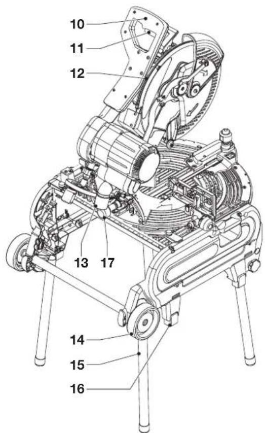
A2
10 Operating handle
11 Trigger switch (mitre saw mode)
12 Fixed upper blade guard
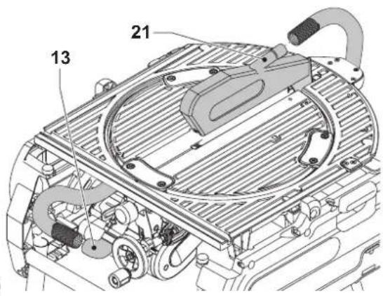
13 Dust extraction adapter
14 Wheel
15 Leg
16 Foot
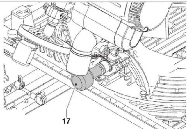
17 Bevel clamp handle
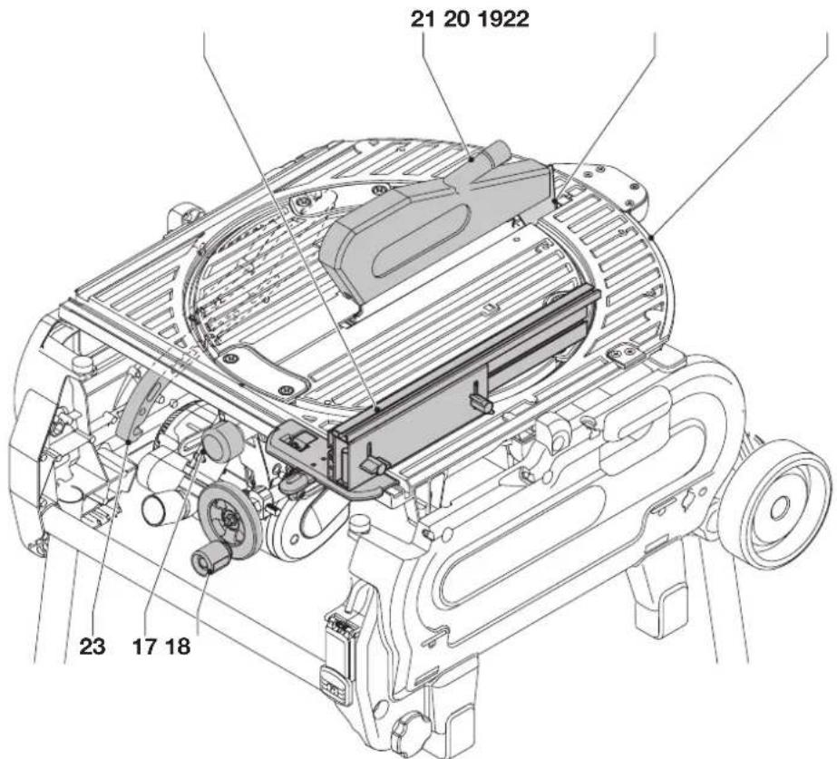
A3
17 Bevel clamp handle
18 Height adjuster
19 Saw bench table
20 Riving knife
21 Upper blade guard
22 Parallel fence
23 Push stick
Optional accessories
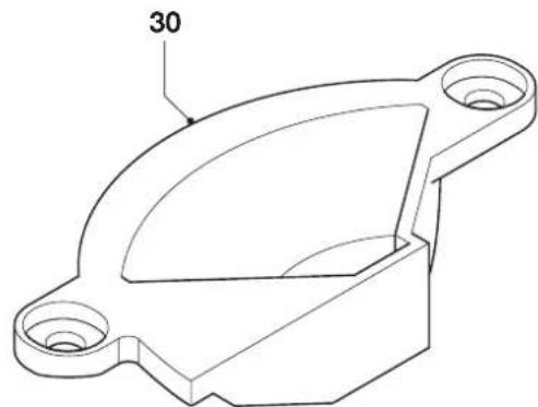
For use in mitre saw mode:
30 Fence insert (DE7120)
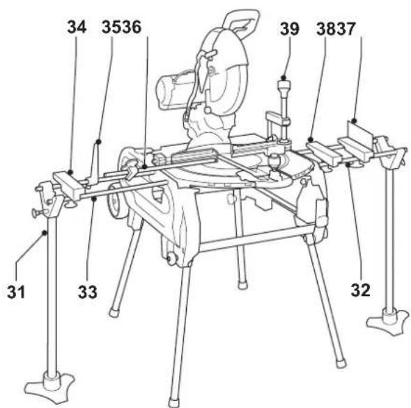
A5
31 Adjustable stand 760 mm (max. height) (DE3474)
32 Support guide rails 1,000 mm (DE3494)
33 Support guide rails 500 mm (DE3491)
34 Inclinable support (DE3495)
35 Swivelling stop (DE3462)
36 Length stop for short workpieces (to be used with guide rails [33]) (DE3460)
37 Support with removable stop (DE3495)
38 Support with stop removed (DE3495)
39 Material clamp (D271051)
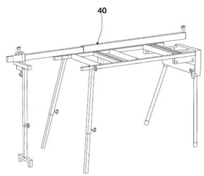
A6
40 Roller support table (DE3497)
For use in saw bench mode:
A7
41 Mitre fence (D271052)
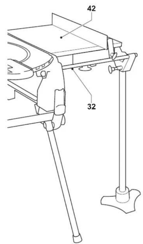
A8
42 Extension table (D271058)
A9
43 Sliding table (D271055)
Push sticks (DE3454) (not shown)
For use in all modes:
A10
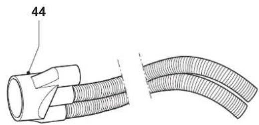
44 Three way dust extraction kit (D271054)
Electrical safety
The electric motor has been designed for one voltage only. Always check that the power supply corresponds to the voltage on the rating plate.
Using an extension cable
If an extension cable is required, use an approved extension cable suitable for the power input of this machine (see technical data). The minimum conductor size is 1.5mm^2 .
When using a cable reel, always unwind the cable completely.
Also refer to the table below.
Conductor size (mm2) Cable rating (Amperes)
| 1.50 15 |
| 2.50 20 |
| 4.00 25 |
| Cable length (m) |
| 7.515 25 30 45 60 |
Voltage Amperes Cable rating (Amperes)
| 230 0 - 2.0 6 6 6 6 6 6 | |
| 2.1 - 3.4 6 6 6 6 6 6 | |
| 3.5 - 5.0 6 6 6 6 10 15 | |
| 5.1 - 7.0 10 10 10 | 10 15 15 |
| 7.1 - 12.0 15 15 15 | 15 20 20 |
| 12.1 - 20.0 20 20 20 | 20 25 - |
Assembly and adjustment

Prior to assembly and adjustment always unplug the tool.
Unpacking the machine and its parts

When moving the machine, always seek assistance.
The machine is too heavy for one person to handle.
- Remove the loose packaging material from the box.
- Lift the machine out of the box.
- Remove the parts box from the interior of the machine.
- Remove any remaining packing material from the machine.
Mounting the feet (fig. B)
With the feet mounted, the machine is suitable for placement on a workbench. To ensure a safe operation, the machine has to be fixed to the workbench.
- Turn the machine upside down.
- Place a foot (16) on each of the mounting locations (51) on the base.
- Slide a nut (52) into the slots (53) located above the mounting locations.
- Insert a bolt (54) fitted with a washer (55) into the feet.
- Tighten the bolts.
- Mount the legs as described below.
- Fold the legs as described below.
- Turn the machine straight up.
• Fix the machine to the workbench.
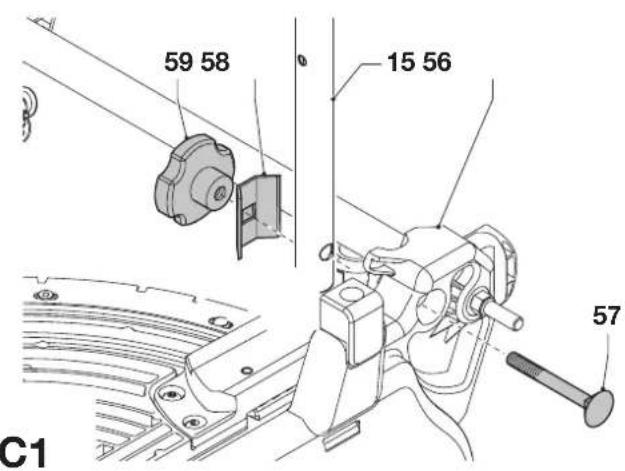
Mounting the legs (fig. C1 & C2)
With the legs mounted, the machine is suitable for stand-alone placement.
- Turn the machine upside down.
- Mount the legs as described below. Beware that the front legs and the rear legs have different lengths. The rear legs are slightly longer than the front legs. Make sure to mount the legs in the correct place.
- Turn the machine straight up. Make sure it is level; adjust the leg clamping height if required.
Rear legs
- Present a leg (15) to each of the mounting points (56) located at the lower edges on the inside of the base (fig. C1).
- Pass a coach bolt (57) from the outside through the holes into the frame and the legs.
- Place a bracket (58) and a lock knob (59) onto the bolts.
- Tighten the lock knobs.
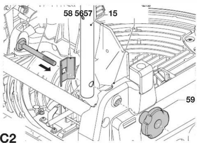
Front legs
- Present a leg (15) to each of the mounting points (56) located at the upper edges on the inside of the base (fig. C2).
- Place a bracket (58) over the legs.
- Pass a coach bolt (57) from the inside through the holes into the brackets, the legs and frame.
- Place a lock knob (59) onto the bolts.
- Tighten the lock knobs.
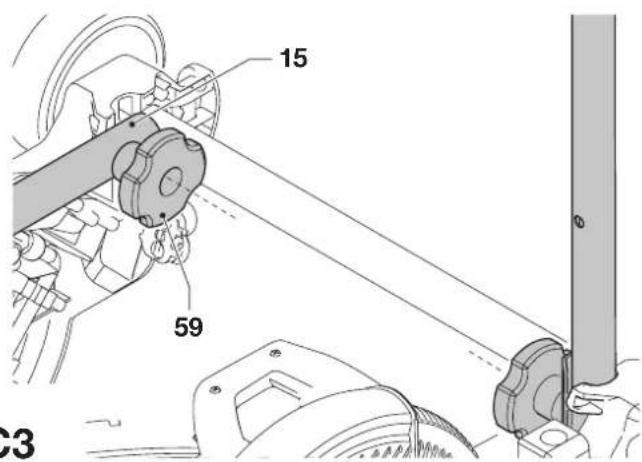
Folding the legs (fig. C3)
The legs can be folded into the base to make the machine suitable for use on a workbench.
- Turn the machine upside down.
- Loosen the lock knob (59) of the first leg (15).
- Fold the leg inwards.
- Tighten the lock knob.
- Repeat as for the other legs.
- Turn the machine straight up.
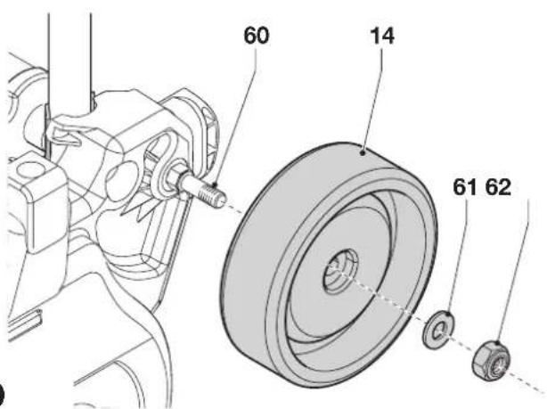
Mounting the wheels (fig. D)
- Place a wheel (14) onto the axles (60) on each side of the machine.
- Place a flat washer (61) and a nut (62) onto the threaded end of the axles.
- Tighten the nuts using the spanner supplied.
Assembly for mitre saw mode
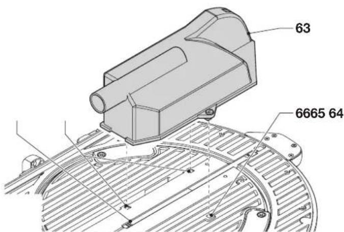
Mounting the under-table guard (fig. E)
The under-table guard (63) is fitted to the top of the saw bench table.
- Place the two fasteners on the left of the guard into the slots (64) on the left of the blade slot (65). Turn the plastic screws counterclockwise.
- Place the guard flat on the table and press the fastener in the slot (66) on the right of the blade slot. Turn the plastic screw counterclockwise.
- To remove, turn the screws clockwise and remove the guard.
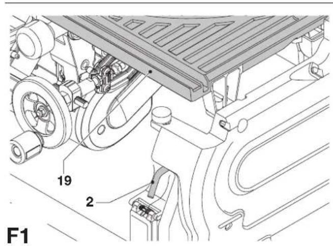
Turning the sawhead and table over (fig. F1 - F4)
- Withhold the saw table (19) with one hand and push the table release lever (2) to the right (fig. F1).
- Push the table downwards at the front (fig. F2) and swing it over completely until the motor assembly is uppermost and the plate (67) engages in the table locking device (68) (fig. F3).
- Push the release lever (69) to the rear whilst holding down the head until the spring-loaded bearing unit (70) can be lifted out of its seating (fig. F4).
- Flip the bearing unit up.
- Holding the head firmly, allow the spring pressure to take the head upwards into its rest position.
Mounting the saw blade (fig. G1 - G4)

The teeth of a new blade are very sharp and can be dangerous.

Always change blades with the machine in mitre saw mode. The maximum diameter blade that can be fitted is 305 mm. The minimum diameter is 300 mm.
- Depress the head lock up release lever (9) to release the lower guard (8), then raise the lower guard as far as possible (fig. G1).
- Loosen the guard bracket screw (71) sufficiently to allow the guard bracket (72) to be raised to permit access to the blade locking screw (73) (fig. G2).
- With the lower guard held in the raised position by the guard bracket screw (71) depress the spindle lock button (74) (fig. G1) with one hand, then use the supplied blade spanner in the other hand to loosen the left-hand threaded blade screw (73) by turning clockwise (fig. G3).

To use the spindle lock, press the button as shown and rotate the spindle by hand until you feel the lock engage. Continue to hold the lock button in to keep the spindle from turning (74, fig. G1).
- Remove the blade locking screw (73) and the outside arbor collar (75) (fig. G4).
- Install the saw blade (76) onto the shoulder (77) provided on the inside arbor collar (78), making sure that the teeth at the bottom edge of the blade are pointing toward the back of the saw (away from the operator).
- Replace the outer arbor collar.
- Tighten the blade locking screw (73) by turning counter-clockwise while holding the spindle lock engaged with your other hand.
- Move the guard bracket (72) down so that it fully covers the blade locking screw (73) (fig. G2).
- Tighten the guard bracket screw (71)

Never press the spindle lock while the blade is rotating.

Be sure to hold the guard bracket down and firmly tighten the guard bracket screws after installing the blade.
Adjustments for mitre saw mode
Your mitre saw was accurately adjusted at the factory. If readjustment due to shipping and handling or any other reason is required, follow the steps below to adjust your saw. Once made, these adjustments should remain accurate.
Checking and adjusting the blade to the fence (fig. H1 - H3)
- Loosen the mitre knob (79) and depress the mitre latch (80) to release the rotating table (5) (fig. H1).
- Swing the rotating table until the latch locates it at the 0^ mitre position. Do not lighten the knob.
- Pull down the head until the blade just enters the saw kerf (81).
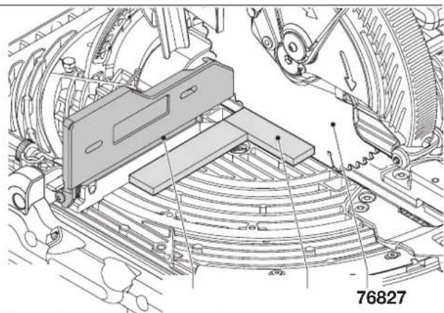
- Place a square (82) against the left side (7) of the fence and blade (76) (fig. H2).

Do not touch the tips of the blade teeth with the square.
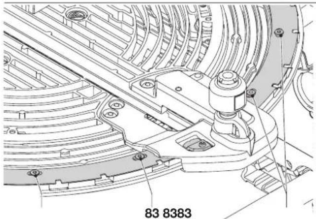
- If adjustment is required, proceed as follows:
- Loosen the screws (83) (fig. H3) and move the scale/rotating table assembly left or right until the blade is at 90^ to the fence as measured with the square (fig. H2).
- Retighten the screws (83) (fig. H3). Pay no attention to the reading of the mitre pointer at this point.
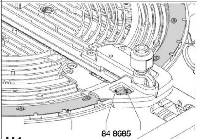
Adjusting the mitre pointer (fig. H1 & H4)
- Loosen the mitre knob (79) and depress the mitre latch (80) to release the rotating table (5) (fig. H1).
- With the mitre knob loose, allow the mitre latch to snap into place as you rotate the mitre arm past zero.
- Observe the pointer (84) and mitre scale (85) (fig. H4). If the pointer does not indicate exactly zero, loosen the screw (86), move the pointer to read 0^ and tighten the screw.
Checking and adjusting the blade to the table (fig. 11 - 13)
- Loosen the bevel clamp knob (17) (fig. 11).
- Press the saw head to the right to ensure it is fully vertical and tighten the bevel clamp handle.
- Pull down the head until the blade just enters the saw kerf (81).
- Place a set square (82) on the table and up against the blade (76) (fig. 12).

Do not touch the tips of the blade teeth with the square.
- If adjustment is required, proceed as follows:
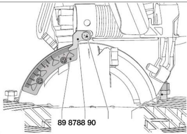
- Loosen the bevel clamp knob (17) (fig. I1) and turn the vertical position adjustment stop screw (87) (fig. I3) in or out until the blade is at 90^ to the table as measured with the square (fig. I2).
- If the bevel pointer (88) does not indicate zero on the bevel scale (89), loosen the screw (90) that secures the pointer and move the pointer as necessary (fig. 13).
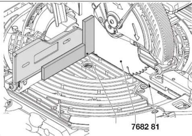
Adjusting the fence (fig. J)
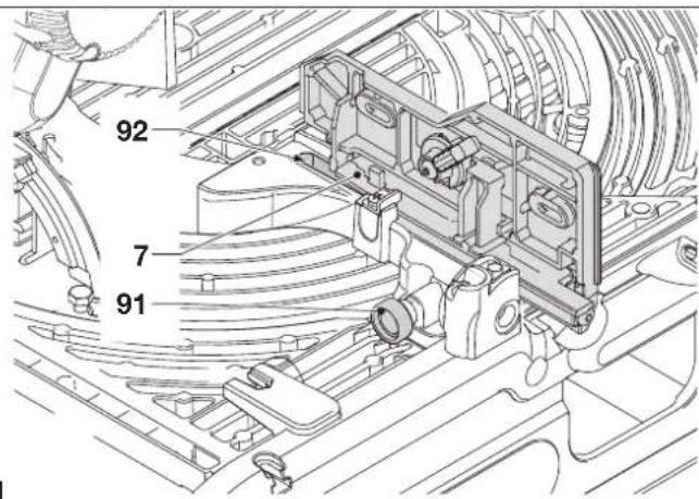
The upper part of the left side of the fence can be adjusted to the left to provide clearance, allowing the saw to bevel to a full 48^ left. To adjust the fence (7):
- Loosen the fence clamping knob (91) and slide the upper part of the side fence to the left.
- Make a dry run with the saw switched off and check for clearance. Adjust the fence to be as close to the blade as practical to provide maximum workpiece support, without interfering with the up and down movement of the arm.
- Tighten the knob securely.

The guide groove (92) can become clogged with sawdust. Use a stick or some low pressure air to clear the guide groove.
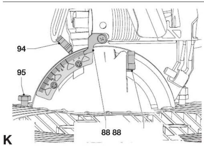
Checking and adjusting the bevel angle (fig. 11, J & K)
- Loosen the fence clamping knob (91) and slide the upper part of the side fence to the left as far as it will go (fig. J).
- Loosen the bevel clamp knob (17) (fig. I1) and with the intermediate bevel position stop (93) turned aside move the saw arm to the left until the angle position stop (94) rests against the bevel position adjustment stop (95) (fig. K). This is the 45^ bevel position.
- If adjustment is required, proceed as follows:
- Turn the bevel position adjustment stop screw (95) in or out as necessary until the pointer (88) indicates 45^ with the angle position stop resting against the bevel position adjustment stop.
Checking and adjusting the intermediate bevel angle (fig. 11, J & L)
The intermediate bevel angle is preset at 30^ , enabling a quick setting for the cutting of crown moulding.
- Loosen the fence clamping knob (91) and slide the upper part of the side fence to the left as far as it will go (fig. J).
- Loosen the bevel clamp knob (17) (fig. 11) and with the intermediate bevel position stop (93) turned into place move the saw arm to the left until the angle position adjustment stop (96) rests on the intermediate bevel position stop (93) (fig. L). This is the 30^ bevel position.
- If adjustment is required, proceed as follows:
- Turn the bevel position adjustment stop screw (96) in or out as necessary until the pointer (88) indicates 30^ with the bevel position adjustment stop resting on the intermediate bevel position stop.
Assembly for saw bench mode
Changing from mitre saw to saw bench mode (fig. A1, M1 - M5)
- Put the blade into 0^ cross-cut position with the rotating table clamp (3) secured (fig. A1).
- Slacken the riving knife clamp knob (97) just enough to allow the riving knife to enter the mounting slot (fig. M1).
- Remove the riving knife (20) from its storage position in the inside of the base.
- Depress the guard release lever (9) to release the blade guard (8), then raise the blade guard as far as possible (fig. A1).
- Slide the riving knife bracket (98) into the mounting slot (99) (fig. M1). Tighten the clamp knob.
- Push the lever (100) to allow the spring loaded upper part of the fence (7) to rest against the rotating table (fig. M2)
- Pull down the sawhead.
- Push the release lever (69) to the rear (fig. M3).
- Push the bearing unit (70) down until notches (101) engage in the locations (102) (fig. M3).

The blade should not foul the lower blade guard.
- Pull the table release lever (2) to the right, lift the front edge of the table (4) fig. M4) and flip it back through 180^ until the plate of the table-locking device (68) automatically engages the latch of the table locking device to secure it in the saw bench mode (fig. M5).
- Remove the under-table guard.
Adjusting the riving knife (fig. N1 & N2)

When adjustments to the riving knife (20) are to be made, it is best to rotate the unit in mitre saw mode (fig. N2). Proceed as described in the section "Changing from saw bench to mitre saw mode".
The correct position is for the top of the riving knife to be no more than 2 mm below the highest tooth of the blade and the body of the radius to be a maximum of 3 - 8 mm from the tips of the saw blade teeth (fig. N1).
- If adjustment is required, proceed as follows:
- Slacken the bolts (102) to adjust the horizontal position of the riving knife.
- Slacken the bolts (103) to adjust the vertical position of the riving knife.
- Securely tighten the bolts.
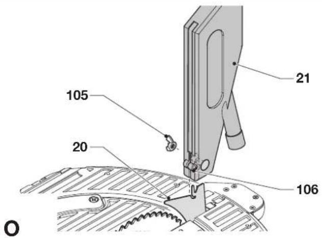
Fitting the upper blade guard (fig. O)
The upper blade guard (21) is designed to be quickly and easily attached to the riving knife (20) once the machine has been set up for saw bench mode.
- Loosen the wingnut (105).
- Holding the guard vertically, align the slot in the rear of the guard with the riving knife.
- Lower the guard over the riving knife (20), making sure that the shaft of the bolt enters the recess.
- Turn the guard into horizontal position, which will lock the guard to the riving knife by the locating screw (106).
- Tighten the wingnut.

Never use your saw in saw bench mode without the upper guard correctly fitted.
Mounting and adjusting the parallel fence (fig. P1 - P5)
The parallel fence (22) can be mounted on either side of the blade.
- Slide the bracket (107) on from the left or the right (fig. P1).
The clamping plate engages behind the front edge of the table. - Slide the fence up against the blade.
- Push the lever (108) down to secure the fence in place.
- Check that the fence is parallel to the blade.
- If adjustment is required, proceed as follows:
- Loosen the lock knobs (109) and slide the fence backwards in order to obtain access to the adjustment bolts (110) in the top of the fence (fig. P2).
- Using the spanner, loosen the adjustment bolts fastening the fence bracket to the fence support.
- Adjust the fence so that it is parallel to the blade by checking the distance between the blade and the fence at the front and rear of the blade.
- When the adjustment has been carried out, re-tighten the adjustment bolts and check again that the fence is parallel to the blade.
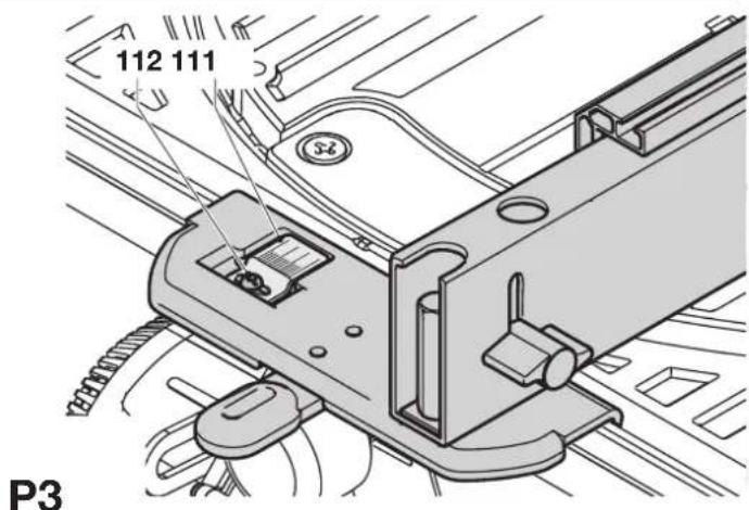
- Check that the pointer (111) indicates zero on the scale (fig. P3). If the pointer does not indicate exactly zero, loosen the screw (112), move the pointer to read 0^ and tighten the screw.
The default set-up of the fence is to the right-hand side of the blade.
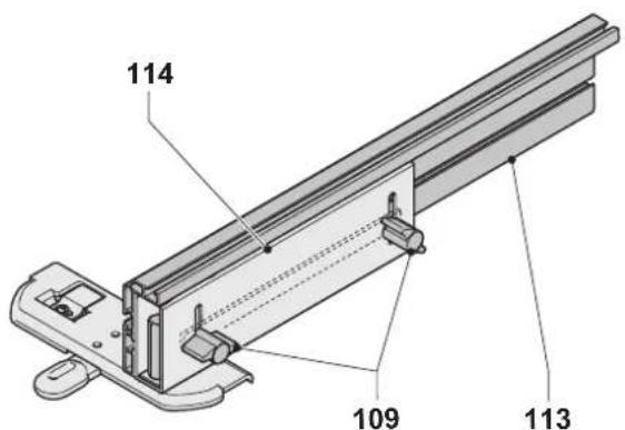
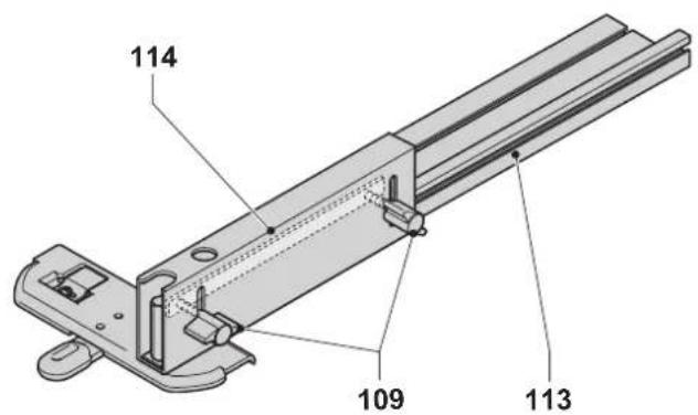
To prepare the fence for use to the left-hand side of the blade, proceed as follows (fig. P4):
- Remove the lock knobs (109).
- Slide the fence profile (113) out of the clamping support.
- Turn the clamping support (114) round and re-fit the lock knobs.
- Slide the fence onto the clamping support.
- Tighten the knobs.
The fence is reversible: the workpiece can be guided along the 75 mm or along the 11 mm face to allow the use of a push stick when ripping thin workpieces (fig P5).
- To set for 11 mm, loosen the fence clamping knobs (109) and slide the fence (113) out of the clamping support (114).
- Turn the fence and re-engage the clamping support in the slot as shown (fig. P5).
- To use with the full height of 75mm , slide the fence into the clamping support with the wide face in the vertical position (fig. P4).

Use the 11 mm profile for ripping low workpieces to allow access between the blade and the fence for the push stick. The rear end of the fence should be level with the front of the riving knife.
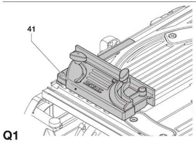
Mounting and adjusting the mitre fence (fig. Q1 - Q4)
The mitre fence (D271052) is available as an option. The mitre fence (41) can be used for mitre cutting when the machine is in saw bench mode (fig. Q1).
- Loosen the clamp knob (115) and swing the guide bar (116) out (fig. Q2). Tighten the clamp knob.
- Slide the fence on the left side on the table (fig. Q3).
- Loosen the lock knob (117).
- Place a square (82) against the fence (41) and the blade (76).
- If adjustment is required, proceed as follows:
- Loosen the nut (118) a few turns and turn the right angle adjustment stop screw (119) (fig. Q4) in or out until the fence is at 90^ to the blade as measured with the square (fig. Q3).
- Tighten the knob (117).
- Check that the pointer (120) indicates zero on the scale (121). Adjust if necessary.
Changing from saw bench to mitre saw mode (fig. A3, E & M1)
- Remove the parallel fence (22), or the mitre fence, if fitted (fig. A3).
- Remove the upper blade guard (21).
- Replace the under-table guard (63) (fig. E).
- Proceed as described in the section "Turning the sawhead and table over".
- Slacken the riving knife clamp knob (97) and remove the riving knife (20), while holding the blade guard (8) (fig. M1).
- Lower the blade guard.
- Place the riving knife in its storage position in the inside of the base.
Instructions for use

- Always observe the safety instructions and applicable regulations.
- The attention of UK users is drawn to the “woodworking machines regulations 1974” and any subsequent amendments.
- Ensure the material to be sawn is firmly secured in place.
- Apply only a gentle pressure to the tool and do not exert side pressure on the saw blade.
- Avoid overloading.
Prior to operation:
- Install the appropriate saw blade. Do not use excessively worn blades. The maximum rotation speed of the tool must not exceed that of the saw blade.
- Do not attempt to cut excessively small pieces.
- Allow the blade to cut freely. Do not force.
- Allow the motor to reach full speed before cutting.
- Make sure all locking knobs and clamp handles are tight.
Switching on and off (fig. R1 - R3)
This machine has two independent switching systems. In mitre saw mode, the trigger switch (11) is used (fig. R1). In saw bench mode, the on/off switch (1) is used (fig. R2).
Mitre saw mode (fig. R1)
A hole (122) is provided in the trigger for insertion of a padlock to lock the switch.
• To run the tool, press the trigger switch (11).
- To stop the tool, release the switch.
Saw bench mode (fig. R2 & R3)
The on/off switch offers multiple advantages:
- no-volt release function: should the power be shut off for some reason, the switch has to be deliberately reactivated.
- motor overload protection device: in case of motor overload, the power supply to the motor will be cut off. If this happens, let the motor to cool for 2 minutes and then press the green start button.
- extra safety: the hinged safety enclosure plate (123) can be locked by passing a padlock through the holes (124 & 125). The plate also serves as an "easy to locate" emergency stop button as pressure on the front of the plate will depress the stop button.
- To switch the machine on, press the green start button (126).
- To switch the machine off, press the red stop button (127).
Locking the switches
- In order to avoid unauthorised use of the machine, lock both switches using padlocks.
Basic saw cuts
Sawing in mitre saw mode
It is dangerous to operate without guarding. Guards must be in position when sawing.
- Make sure that the under-table guard does not become clogged with sawdust.
• Always clamp the workpiece when cutting non-ferrous metals.
General handling
- In the mitre saw mode, the sawhead is automatically locked in the upper "park"-position.
- Squeezing the guard release lever will unlock the sawhead. Moving the sawhead down retracts the movable lower guard.
- Never seek to prevent the lower guard returning to its park position when the cut is completed.
- The minimum length of offcut material is 10 mm.
- When cutting short material (min. 190 mm to the left or the right of the blade), the use of the optional material clamp is recommended.
- When cutting UPVC sections, a supporting piece made out of timber with a complementary profile should be placed beneath the material being cut to provide the correct level of support.
Vertical straight cross cut (fig. S1)
- Loosen the mitre knob (79) and depress the mitre latch (80).
- Engage the mitre latch at the 0^ position and tighten the mitre knob.
- Place the wood to be cut against the fence (7).
- Take hold of the operation handle (10) and press in the guard release lever (9).
- Press the trigger switch (11) to start the motor.
- Depress the head to allow the blade to cut through timber and enter the saw kerf (81).
- After completing the cut, release the switch and wait for the saw blade to come to a complete stillstand before returning the head to its upper rest position.
Vertical mitre cross-cut (fig. S2)
- Loosen the mitre knob (79) and depress the mitre latch (80). Move the rotating table left or right to the required angle.
- The mitre latch will automatically locate at 15^ , 22.5^ , 35.3^ and 45^ both left and right. If any intermediate angle is required hold the head firmly and lock by tightening the mitre knob.
• Always ensure that the mitre knob is locked tightly before cutting.
• Proceed as for a vertical straight cross-cut.

When mitring the end of a piece of wood with a small off-cut, position the wood to ensure that the off-cut is to the side of the blade with the greater angle to the fence: left mitre, off-cut to the right right mitre, off-cut to the left.
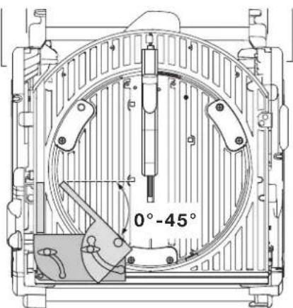
Bevel cross-cut (fig. S3)
Bevel angles can be set from 48^ left to 2^ right and can be cut with the rotating table set between zero and a maximum of 45^ mitre position left or right.
- Loosen the fence clamping knob (89) and slide the upper part of the side fence to the left as far as it will go.
- Loosen the bevel clamp knob (17) and set the bevel as desired.
- Tighten the bevel clamp knob firmly.
- Proceed as for a vertical straight cross-cut.
Compound mitre (fig T1 - T4)
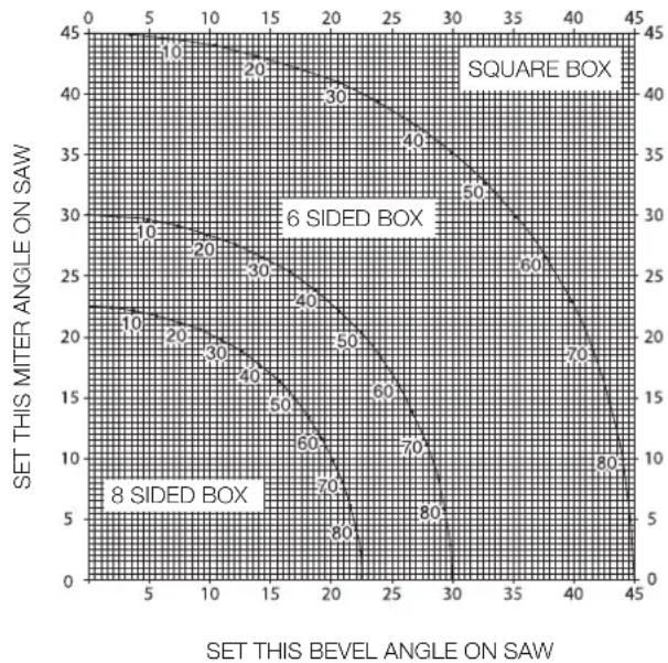
A compound mitre is a cut made using a mitre angle (fig. T1) and a bevel angle (fig. T2) at the same time. This is the type of cut used to make frames or boxes with slanting sides like the one shown in fig. T3.

If the cutting angle varies from cut to cut, check that the bevel clamp knob and the mitre lock knob are securely tightened. These knobs must be tightened after making any changes in bevel or mitre.
- The chart shown below will assist you in selecting the proper bevel and mitre settings for common compound mitre cuts. To use the chart, select the desired angle "A" (fig. T4) of your project and locate that angle on the appropriate arc in the chart. From that point follow the chart straight down to find the correct bevel angle and straight across to find the correct mitre angle.
- Set your saw to the prescribed angles and make a few trial cuts.
• Practice fitting the cut pieces together. - Example: To make a 4 sided box with 25^ exterior angles (angle "A") (fig. T4), use the upper right arc. Find 25^ on the arc scale. Follow the horizontal intersecting line to either side to get the mitre angle setting on the saw (23^) . Likewise follow the vertical intersecting line to the top or bottom to get the bevel angle setting on the saw (40^) . Always try cuts on a few scrap pieces of wood to verify the settings on the saw.
line
| SET THIS MITER ANGLE ON SAW | SET THIS BEVEL ANGLE ON SAW | | :--- | :--- | | 45 | 0 | | 40 | 10 | | 35 | 20 | | 30 | 30 | | 25 | 40 | | 20 | 50 | | 15 | 60 | | 10 | 70 | | 5 | 80 | | 0 | 90 |ANGLE OF SIDE OF BOX (ANGLE"A")
Cutting base mouldings
The cutting of base moulding is performed at a 45^ bevel angle.
• Always make a dry run without power before making any cuts.
- All cuts are made with the back of the moulding laying flat on the saw.
Inside corner
Left side
- Position the moulding with top of the moulding against the fence.
- Save the left side of the cut.
- Right side
- Position the moulding with the bottom of the moulding against the fence.
- Save the left side of the cut.
Outside corner
Left side
- Position the moulding with the bottom of the moulding against the fence.
- Save the right side of the cut.
- Right side
- Position the moulding with top of the moulding against the fence.
- Save the right side of the cut.
Cutting crown mouldings
The cutting of crown moulding is performed in a compound mitre. In order to achieve extreme accuracy, your saw has pre-set angle positions at 35.3^ mitre and 30^ bevel. These settings are for standard crown mouldings with 45^ angles at the top and 45^ angles at the bottom.
- Make test cuts using scrap material before doing the final cuts.
- All cuts are made in a left bevel and with the back of the moulding against the base.
Inside corner
Left side
- Top of the moulding against the fence.
- Mitre right.
- Save the left side of the cut.
- Right side
- Bottom of the moulding against the fence.
- Mitre left.
- Save the left side of the cut.
Outside corner
- Left side
- Bottom of the moulding against the fence.
- Mitre left.
- Save the right side of the cut.
- Right side
- Top of the moulding against the fence.
- Mitre right.
- Save the right side of the cut.
Sawing in the bench mode
• Always use the riving knife.
- Always ensure that the riving knife and blade guard are correctly aligned.
- Always ensure that the mitre saw is set and locked in 0^ mitre.

Do not cut metal in this mode.
Ripping (fig. U1 & U3)
- Set the bevel angle to 0^ .
- Adjust the saw blade height.
- Set the parallel fence to the required distance.
- Hold the workpiece flat on the table and against the fence. Keep the workpiece approx. 25 mm away from the saw blade.
- Keep both hands away from the path of the saw blade.
- Switch the machine on and allow the saw blade to reach full speed.
- Slowly feed the workpiece underneath the upper blade guard, keeping it firmly pressed against the fence. Allow the teeth to cut, and do not force the workpiece through the saw blade. The saw blade speed should be kept constant.
- Remember to use the push stick (23) when close to the blade.
- After completing the cut, switch the machine off, allow the saw blade to stop and remove the workpiece.

Never push or hold the free or cut-off side of the workpiece.

Always use a push stick when ripping small workpieces.
Bevel cuts (fig. U2)
- Set the required bevel angle.
• Proceed as for ripping.
Cross-cutting (fig. V1)
- Set the bevel angle to 0^ .
- Adjust the saw blade height.
- Set the mitre fence to 0^ .
- Proceed as for ripping, only use the mitre fence to push the workpiece through the blade.
Bevel cross-cutting
- Set the required bevel angle.
• Proceed as for cross-cutting.
- Set the mitre fence to the required angle.
• Proceed as for cross-cutting.
Optional attachments

Prior to assembling any accessories always unplug the machine.
Dust extraction kit (fig. W1 & W2)
This machine is provided with two dust extraction points for use in each mode.
- When sawing wood, connect a dust extraction device designed in accordance with the relevant regulations regarding dust emission.
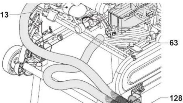
Connecting - mitre saw position (fig. W1)
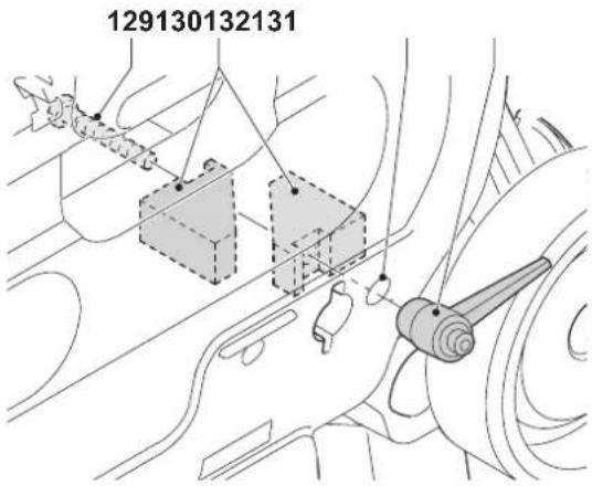
- Connect the one end of the first hose to the dust extraction adaptor (13).
- Insert the other end of the hose into the middle inlet port of the manifold (128).
- Connect the one end of the other hose to the under-table guard (63).
- Insert the other end of the hose into the outer inlet port of the manifold.
Connecting - saw bench position (fig. W2)
- Proceed as for mitre saw position, only connect the hose from the under-table guard to the saw blade guard (21).
Mitre saw extra support/length stop (fig. A5)
The extra support and length stop can be mounted on the left-hand side or on the right-hand side, or with two sets on either side.
- Fit the items 31 - 39 onto the two guide rails (32 & 33).
- Use the inclinable support (34) for cross-cutting 210 mm wide boards (15 mm thick).
Roller support table (fig. A6)
The roller support table (40) is used to support long workpieces. In mitre saw mode, the roller support table can be mounted on the left-hand side or on the right-hand side, or with two sets on either side. In saw bench mode, it can also be mounted in front or at the rear of the saw table.
Side extension table (fig. A8)
The side extension table increases the distance from the rip fence to the blade to 600 mm or more, depending on the rod length fitted to the machine and the clamped position of the table. The side extension table must be used in conjunction with guide rails (33) (option). The adjustable table is equipped with an engraved scale along its front edge and mounted on a sturdy base which clamps to the guide rods.
- Fit the extension table to the right-hand side of the machine for continuity of the distance scale on both tables.
Sliding table (fig. A9)
This sliding table (43) allows for board sizes to the left of the blade up to 1200 x 900 mm.
The guide rods are mounted on a sturdy alloy extrusion which is quickly detachable from the machine and yet fully adjustable is all planes.
The fence incorporates a full length measuring tape for quick positioning of an adjustable stop and an adjustable support for narrow workpieces.
Saw bench guard
In countries where the Suva-type guard is a legal requirement, it is supplied as standard. In other countries, it is available as an option.
Transporting (fig Y)

Always transport the machine in saw bench mode with the upper blade guard fitted.
The castor wheels provide an easier transport of the machine.
- Fold the rear legs into the base.
- Fold the front legs out of the base.
- Lift the machine by the legs.

When carrying the machine, always seek assistance. The machine is too heavy for one person to handle.
Maintenance
Your D=WALT power tool has been designed to operate over a long period of time with a minimum of maintenance. Continuous satisfactory operation depends upon proper tool care and regular cleaning.

Lubrication
The bearings of the motor are pre-lubricated and watertight.
- Slightly oil the rotating table bearing surface where it slides on the lip of the fixed table at regular intervals.
• Periodically lubricate the depth of cut screwthread. - Clean the parts subject to accumulation of sawdust and chips periodically with a dry brush.
Cam adjustment (fig Z1 - Z3)
To take out the clearance between the two tables, proceed as follows:
- Rotate the machine into saw bench mode.
- Remove the screws (138) and the retainer plate (139).
- Loosen the screw (140) of the adjustment cam (141).
- Rotate the adjustment cam using a pair of needle nose pliers.
- Hold the adjustment cam with the pliers and tighten the screw.
- Replace the retainer plate and tighten the screws.
- Rotate the machine into mitre saw mode. Check the force that is needed to mitre the saw. Repeat the above steps if the force needed is too high.

Unwanted tools and the environment
Take your tool to an authorized DeWALT repair agent where it will be disposed of in an environmentally safe way.
GUARANTEE
• 30 DAY NO RISK SATISFACTION GUARANTEE •
If you are not completely satisfied with the performance of your DeWALT machine, simply return it within 30 days, complete as purchased, to the point of purchase, for a full refund or exchange. Proof of purchase must be produced.
• ONE YEAR FREE SERVICE CONTRACT •
If you need maintenance or service for your DEWALT machine, in the 12 months following purchase, it will be undertaken free of charge at an authorized DEWALT repair agent. Proof of purchase must be produced. Includes labour and spare parts for Power Tools. Excludes accessories.
• ONE YEAR WARRANTY •
If your DEWALT product becomes defective due to faulty materials or workmanship within 12 months from the date of purchase, we guarantee to replace all defective parts free of charge or, at our discretion,
replace the unit free of charge provided that:
• The product has not been misused.
• Repairs have not been attempted by unauthorized persons.
• Proof of purchase date is produced.
This guarantee is offered as an extra benefit and is additional to consumers statutory rights.
For the location of your nearest authorized DeWALT repair agent, please use the appropriate telephone number on the back of this manual. Alternatively, a list of authorized DeWALT repair agents and full details on our after-sales service are available on the Internet at www.2helpU.com
SIERRA DE DOBLE MODALIDAD D27105
¡Enhorabuena!
Director Engineering and Product Development Horst Großmann

text_image
X. JopmanL'emballage contient:
Director Engineering and Product Development Horst Großmann

text_image
X. JopmanDeWALT, Richard-Klinger-Straße 11, D-65510, Idstein, Duitsland
Director Engineering and Product Development Horst Großmann

text_image
X. JopsmannDeWALT, Richard-Klinger-Straße 11, D-65510, Idstein, Tyskland
Director Engineering and Product Development Horst Großmann

text_image
X. JopmanDEWALT, Richard-Klinger-Straße 11, D-65510, Idstein, Alemanha
11 Retire as chaves de ajuste
Dobrar as pernas (fig. C3)
Director Engineering and Product Development Horst Großmann

text_image
X. JopmanDirector Engineering and Product Development Horst Großmann

text_image
X. JopsmannDeWALT, Richard-Klinger-Straße 11, D-65510, Idstein, Tyskland
ÇOK AMAÇLI TESTERE D27105
Tebrikler!
35 Döngülü duruş (DE3462)