WMN4070TT - TV wall mount SAMSUNG - Free user manual and instructions
Find the device manual for free WMN4070TT SAMSUNG in PDF.

| Product Type | Wall mount for TV |
| Brand | Samsung |
| Model | WMN4070TT |
| Dimensions (W × H × D) | 248 × 250.2 × 53 mm |
| Mount weight | 3.9 kg |
| VESA standard | 200 × 200 mm |
| Power supply | None (passive mount) |
| Vertical tilt | -15° to 15° |
| Horizontal rotation | -20° to 20° |
| Material | Steel and plastic |
| Color | Black (typical) |
| Maximum supported weight | Up to 50 kg (estimated) |
| Compatible wall types | Concrete, wood, plywood (minimum thickness 50 mm) |
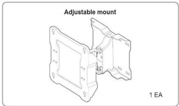
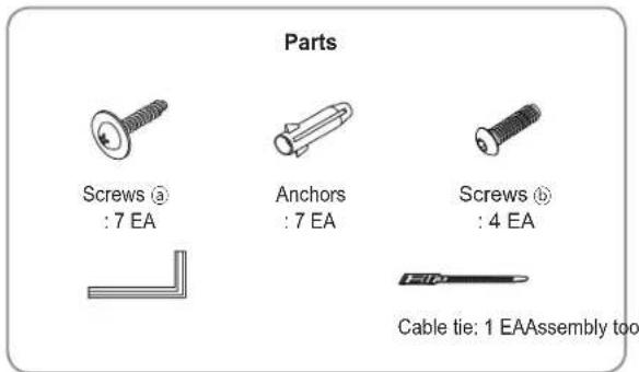
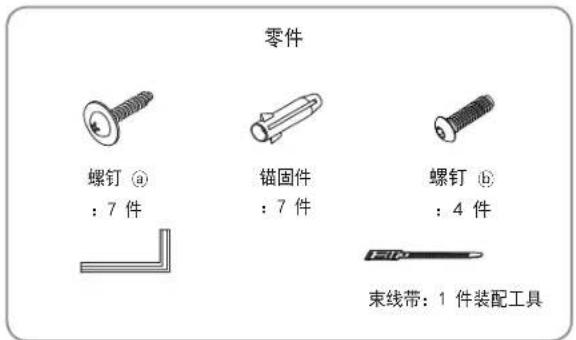
| Package contents | Adjustable bracket, screws ⓐ (7), wall anchors (7), screws ⓑ (4), cable tie (1), mounting tool |
| Care and cleaning | Wipe with a soft, dry cloth |
| Safety | Professional installation required, do not overload, keep out of reach of children |
| Spare parts and repairability | Screws and wall anchors provided; parts available from manufacturer |
Frequently Asked Questions - WMN4070TT SAMSUNG
User questions about WMN4070TT SAMSUNG
0 question about this device. Answer the ones you know or ask your own.
Ask a new question about this device
Download the instructions for your TV wall mount in PDF format for free! Find your manual WMN4070TT - SAMSUNG and take your electronic device back in hand. On this page are published all the documents necessary for the use of your device. WMN4070TT by SAMSUNG.
USER MANUAL WMN4070TT SAMSUNG
Adjustable Wall Mount User Guide WMN4070TT

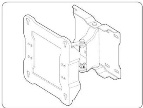
Finished wall mount
natural_image
Technical line drawing of a mechanical housing assembly (no text or symbols)
Components
* Please make sure to use the components and parts supplied with the product.

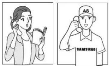
Safety precautions
Make sure that an installation engineer specified by your dealer installs the product.
Make sure that an installation engineer specified by your dealer moves or replaces the product after the installation.
natural_image
Illustration of two people: one holding a book and the other adjusting a cap with 'AS' text (no readable text or symbols)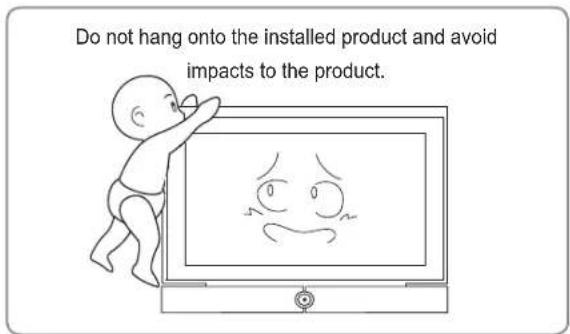
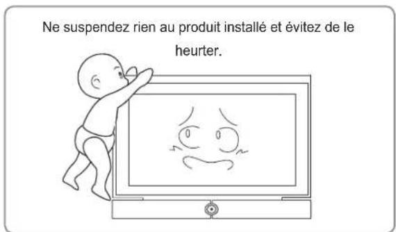
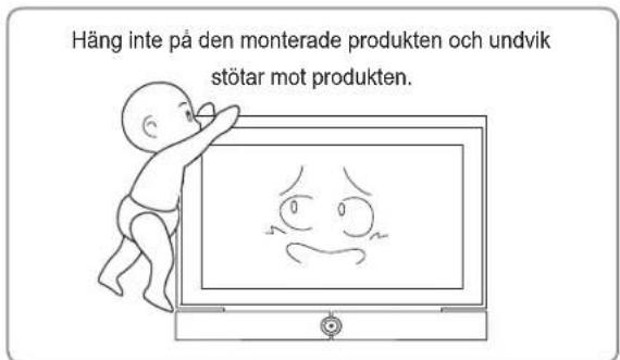
- Do not let children play underneath the product when it is installed. Children may hit their heads against the edge of the product.
- Take care when you adjust the angle or rotate the product because the back of the product may make contact with the wall.
(You can prevent damage to the product and the wall by attaching sponges to the 4 edges of the product.) - Do not install the product in a hot, humid location or on a weak wall that is unable to sustain the weight of the product.
- Do not insert your hand into the groove at the bottom of the TV while installing the TV onto the wall mount as this may result in an electric shock.
- Make sure to cover the groove at the bottom of the TV that becomes visible after removing the stand using the separate cover supplied with the TV.

Installing the wall mount
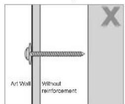
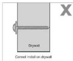
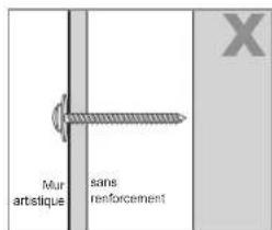
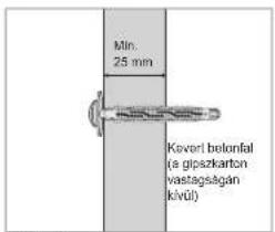
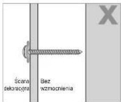
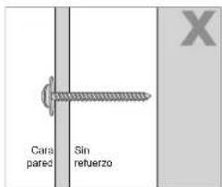
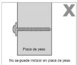
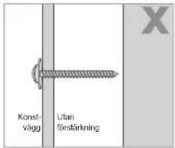
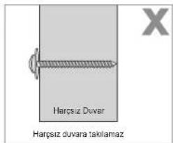
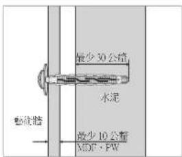
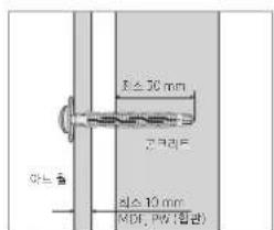
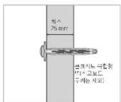
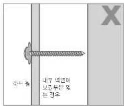
⚠️ Check the type of the wall before installing.
Standard Installation Requirements by Wall Type
- Can only be mounted on a concrete or interior wall of sufficient thickness. Refer to the diagrams below.
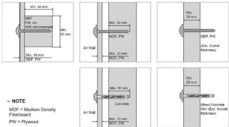
- NOTE
MDF = Medium Density
Fiberboard
PW = Plywood
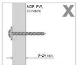
- Cannot be mounted on unreinforced wall or drywall surfaces.
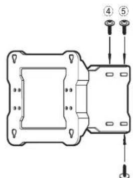
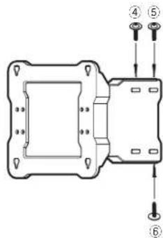
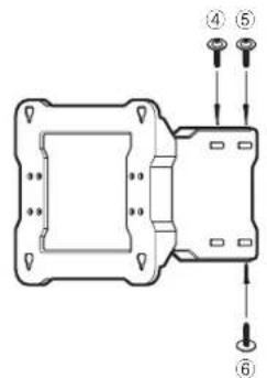
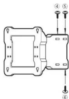
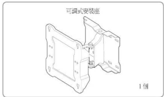
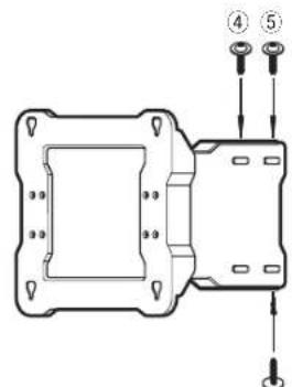
1 Fix the adjustable mount onto the wall as shown by the figure.
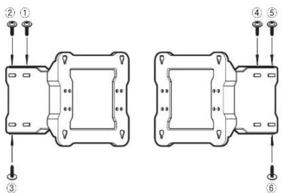
Fix the adjustable mount onto the wall with anchors and screws ④ from ① to ⑥ in this order. (Moving the adjustable mount while fastening the screws onto the wall makes it easier to fasten the screws.)
If you cannot fasten the anchors and screws at the specified positions, fasten them at the nearest possible positions.
Fixing the anchors and screws ⓐ
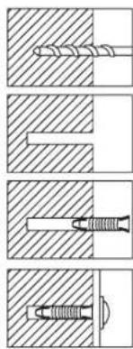
Drill a hole using a 9X70 drill bit.
(WMN-2370: 4X25)
Clean the inside of the hole.
Insert the enclosed anchor into the hole.
Align the adjustable mount with the hole and fasten the screw ⓐ.
* When you drill a hole in the wall, make sure to use a drill bit with the specified diameter.
Failing to do so may result in a safety issue.
Check the strength of the wall, and if the wall is insufficiently strong, reinforce the wall before installing the product on the wall.
The screws and anchors supplied with the product are to fix the product onto wood or concrete.
Check the material of the wall and use appropriate fixing screws depending on the type of material such as plaster board, marble or iron plate.
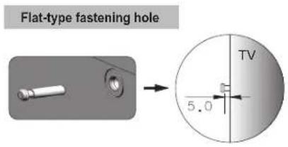
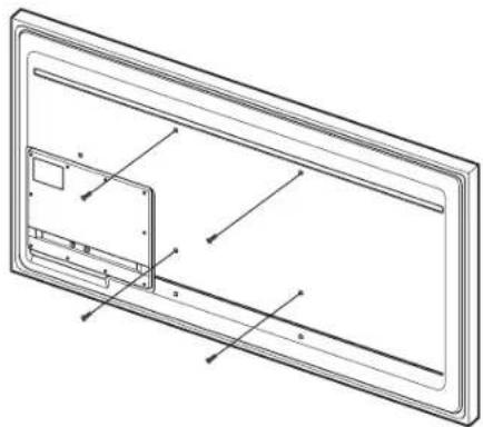
2 Remove the screws from the back of the TV and fasten the 4 screws (b) onto the back of the TV with the enclosed assembly tool until each of the screws projects out by 5mm. To hang the TV onto the adjustable mount, a projected part of at least 5 mm is necessary.
natural_image
Technical line drawing of a rectangular panel with internal components and mounting holes (no text or symbols)Hang the TV onto the wall mount and make sure to check if the TV has been installed properly onto the wall mount by observing the assembled TV as you move the wall mount from left to right.
Take care not to hurt your fingers when you install the TV or adjust the wall mount.
Make sure to fix the wall mount onto the wall firmly. If the TV falls, it may result in injury or damage to the product.
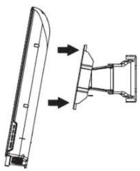
3 Pull the wall mount brackets as far forward as possible and hang the TV onto the wall mount at the specified positions as shown by the figure while 2 persons are holding the TV.
natural_image
Technical line drawing of a mechanical component with two views (top and side), no text or symbols present.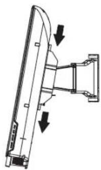
natural_image
Technical line drawing of a mechanical assembly with two downward arrows indicating motion or force directions (no text or symbols present)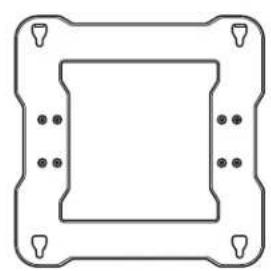
natural_image
Pure geometric diagram of a square frame with corner holes and dots, no text or symbols present
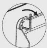
After fixing the TV onto the wall mount, firmly fasten the 4 screws ⓑ so that the TV and the wall mount are completely fastened.
(Fastening force: 10 \~ 15 Kg)
- Tie the power cord and the other cables with the enclosed cable tie as shown by the figure and make sure that the cables do not come loose when the wall mount is adjusted.
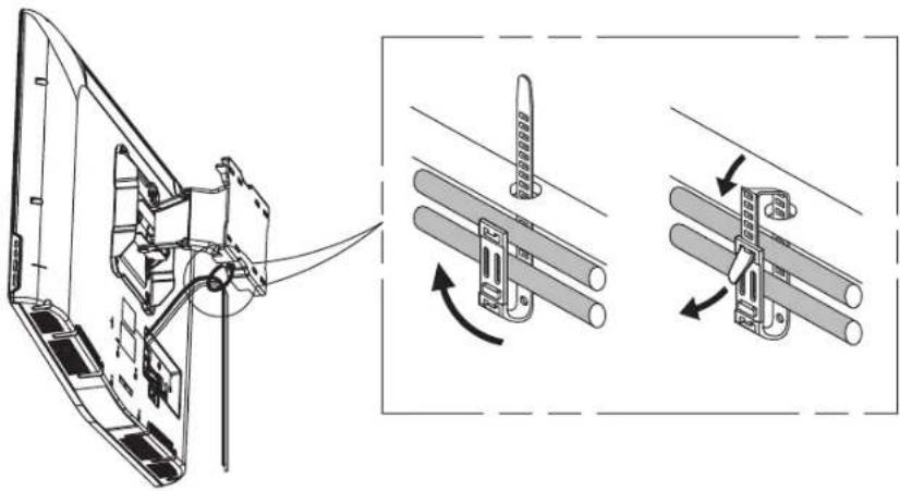
* After connecting the cables and pulling the adjustable mount as far forward as possible, arrange the cables using the cable tie that has been passed through the specified hole in the adjustable mount as shown by the figure.
The cable will then not interfere with the wall mount.
Check the operation 2 or 3 times and if there is no problem, fix the wall molding.


Adjusting the wall mount angle
* This product has adopted a Smooth Moving Mechanism so that it always moves very smoothly.
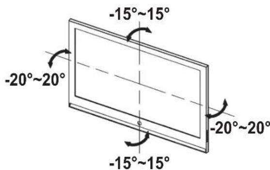
Adjust the angle of the product carefully. Using excessive force may result in the product hitting the wall and becoming damaged. Adjust the horizontal angle by holding both sides of the product. When you adjust the vertical angle, hold the top center of the product. Then you can smoothly adjust the angle.
* You can adjust the angle up to -15^ 15^ horizontally and up to -20^ 20^ vertically. The allowed adjustable angle may differ depending on the model.

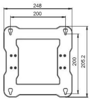
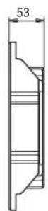
Product specifications
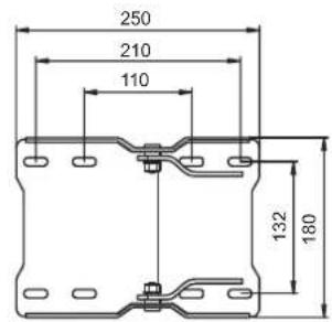
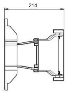
[ Main Body Fixing Part ] [ Screw Fixing Part ]

Specifications
| Width (mm) 248 | |
| Height (mm) 250.2 | |
| Depth (mm) 53 | |
| Weight (Kg) 3.9 | |
| Wall mount VESA specifications 200 X 200 | |
The product appearance and specifications are subject to change for product improvement purposes without prior notice.
natural_image
Technical line drawing of a mechanical housing assembly (no text or symbols)
Composants
③
⑥
natural_image
Four-panel diagram showing different types of screw and drill bit configurations (no text or labels)natural_image
Technical line drawing of a rectangular frame with internal components and alignment markers (no text or symbols)natural_image
Technical line drawing of a mechanical component with two views (top and side), no text or symbols present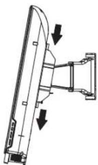
natural_image
Technical line drawing of a mechanical assembly with two downward arrows indicating motion or force directions (no text or symbols present)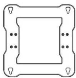
natural_image
Pure technical diagram of a square frame with corner holes and mounting holes (no text or symbols)
natural_image
Technical line drawing of a mechanical housing or bracket assembly (no text or symbols)
Komponenten
natural_image
Diagram showing four different types of screw and drill bit configurations (no text or labels)natural_image
Technical line drawing of a rectangular panel with internal components and mounting holes (no text or symbols)natural_image
Technical line drawing of a mechanical component with two views (top and side), no text or symbols present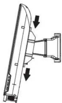
natural_image
Technical line drawing of a mechanical assembly with two downward arrows indicating motion or force (no text or symbols present)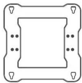
natural_image
Pure geometric diagram of a square frame with corner holes and dots, no text or symbols present.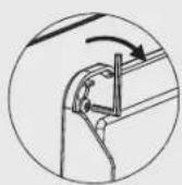
natural_image
Technical line drawing of a mechanical housing assembly (no text or symbols)
Componenti
natural_image
Illustration of two people: one holding a book and the other adjusting a cap with 'AS' text (no readable text or symbols)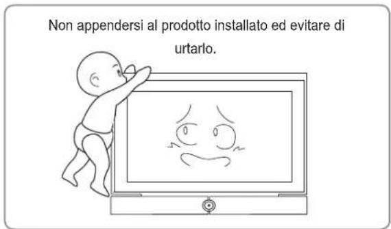
natural_image
Diagram showing four different types of screw and nut configurations in cross-sectional views (no text or labels)natural_image
Technical line drawing of a rectangular frame with internal components and mounting holes (no text or symbols)natural_image
Technical line drawing of a mechanical component with two views: one showing a curved top and the other showing a bracket with arrows indicating direction (no text or symbols)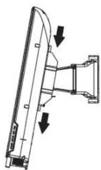
natural_image
Technical line drawing of a mechanical assembly with two downward arrows indicating motion or force directions (no text or symbols present)
natural_image
Pure geometric diagram of a square frame with corner holes and dots, no text or symbols present.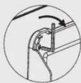
natural_image
Technical line drawing of a mechanical housing assembly (no text or symbols)
Részegységek
natural_image
Pure technical diagram showing five different screw and nut assembly states without any text or symbolsnatural_image
Technical line drawing of a rectangular device with internal components and mounting holes (no text or symbols)natural_image
Technical line drawing of a mechanical component with two views: one showing a curved blade and the other showing a bracket assembly (no text or symbols)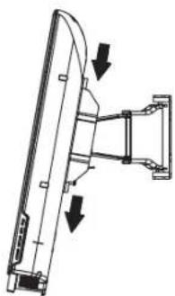
natural_image
Technical line drawing of a mechanical assembly with two downward arrows indicating motion or force (no text or symbols present)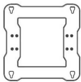
natural_image
Pure technical diagram of a square frame with mounting holes and corner markers (no text or symbols)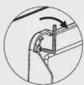
natural_image
Technical line drawing of a mechanical housing assembly (no text or symbols)
Elementy
natural_image
Illustration of two people: one holding a book and the other using a smartphone to listen (no text or symbols present)
natural_image
Four-panel diagram showing different screw and nut assembly states (no text or labels)natural_image
Technical line drawing of a rectangular device with internal components and mounting holes (no text or symbols)natural_image
Technical line drawing of a mechanical component with two views: one showing a curved blade and the other showing a bracket (no text or symbols)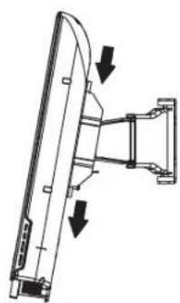
natural_image
Technical line drawing of a mechanical assembly with two downward arrows indicating motion or force directions (no text or symbols present)
natural_image
Pure technical diagram of a square frame with corner holes and mounting holes (no text or symbols)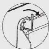
natural_image
Technical line drawing of a mechanical housing component with mounting holes and internal components (no text or symbols)
Componentes
natural_image
Two cartoon illustrations: one showing a person holding a book and the other showing a person wearing a cap with 'AS' and 'SAMSUNG' text (no readable text or symbols in the figures themselves)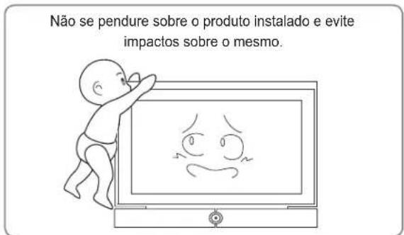
natural_image
Technical line drawing of a rectangular frame with internal components and mounting holes (no text or symbols)natural_image
Technical line drawing of a mechanical component with two views (top and side), no text or symbols present.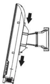
natural_image
Technical line drawing of a mechanical assembly with two downward arrows indicating direction (no text or symbols)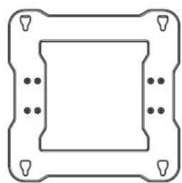
natural_image
Pure technical diagram of a square frame with corner holes and mounting points (no text or symbols)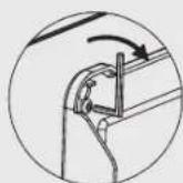
natural_image
Technical line drawing of a mechanical housing assembly (no text or symbols)
Компоненты
natural_image
Cartoon illustration of a baby pointing at a TV screen displaying a sad face (no text or symbols present)
natural_image
Four-panel diagram showing different types of screw and nut components, no text or symbols presentnatural_image
Technical line drawing of a rectangular device with internal components and mounting holes (no text or symbols)natural_image
Technical line drawing of a mechanical component with two views: one showing a curved blade and arrow indicator, the other showing a bracket assembly (no text or symbols)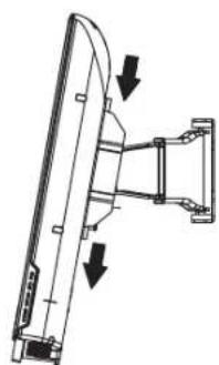
natural_image
Diagram of a computer monitor with two directional arrows indicating orientation (no text or symbols)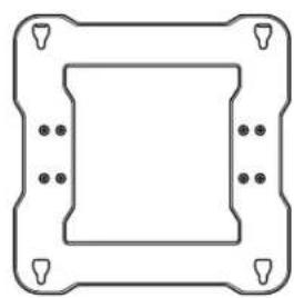
natural_image
Pure technical diagram of a square frame with mounting holes and bolt holes (no text or symbols)
natural_image
Technical line drawing of a mechanical housing assembly (no text or symbols)
Componentes
natural_image
Illustration of two people: one holding a book and the other using a smartphone to listen (no text or symbols present)natural_image
Illustration of a baby reaching toward a TV screen displaying a sad face (no text or symbols present)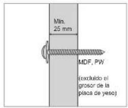
natural_image
Pure technical diagram showing five different screw and nut assembly states without any text or symbolsnatural_image
Technical line drawing of a rectangular frame with internal components and mounting holes (no text or symbols)natural_image
Technical line drawing of a mechanical component with two views: one showing a curved blade and the other showing a flanged bracket (no text or symbols)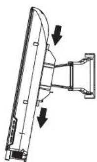
natural_image
Technical line drawing of a mechanical assembly with two downward arrows indicating motion or force (no text or symbols present)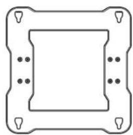
natural_image
Pure technical diagram of a square frame with corner holes and mounting points (no text or symbols)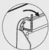
natural_image
Technical line drawing of a mechanical housing assembly (no text or symbols)
Komponenter
natural_image
Technical line drawing of a mechanical component with mounting holes and a housing (no text or symbols)natural_image
Pure technical diagram showing five different screw and nut assembly states without any text or symbolsnatural_image
Technical line drawing of a rectangular frame with internal components and mounting holes (no text or symbols)natural_image
Technical line drawing of a mechanical component with two views: top view shows a curved blade, bottom view shows a bracket with arrows indicating direction (no text or symbols)
natural_image
Technical line drawing of a mechanical assembly with two downward arrows indicating motion or force directions (no text or symbols present)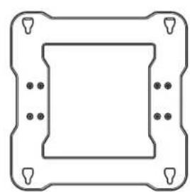
natural_image
Pure technical diagram of a square component with mounting holes and corner markers (no text or symbols)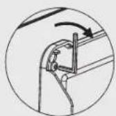
natural_image
Technical line drawing of a mechanical housing assembly (no text or symbols)
Bileşenler
natural_image
Technical line drawing of a mechanical bracket assembly (no text or symbols)1 adet
Parçalar

Vidalar a
: 7 adet

Dübeller
:7 adet

Vidalar ⑥
: 4 adet

natural_image
Illustration of two people: one holding a book and the other wearing a cap with 'A8' and 'SAMSUNG' text (no readable document content)natural_image
Cartoon illustration of a baby pointing at a TV screen displaying a sad face (no text or symbols present)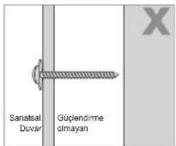
natural_image
Technical line drawing of a 3D rectangular panel with internal components and mounting holes (no text or symbols)natural_image
Technical line drawing of a mechanical component with two views: one showing a curved blade and the other showing a bracket assembly (no text or symbols)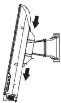
natural_image
Technical line drawing of a mechanical assembly with two downward arrows indicating motion or force directions (no text or symbols present)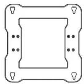
natural_image
Pure geometric diagram of a square frame with corner holes and dots, no text or symbols present.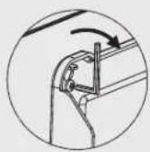
natural_image
Technical line drawing of a mechanical bracket assembly (no text or symbols)
部件
* 请务必使用随产品提供的部件。

natural_image
Two cartoon illustrations: one showing a person holding a notebook and the other showing a person wearing a cap with 'AS' and 'SAMSUNG' text (no readable text or symbols)natural_image
Illustration of a baby reaching toward a TV displaying a sad face (no text or symbols present)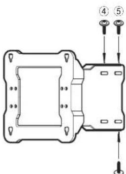
③
natural_image
Technical line drawing of a rectangular device with internal components and mounting holes (no text or symbols)natural_image
Technical line drawing of a mechanical component with two views: top view shows a curved blade, bottom view shows a bracket with arrows indicating direction (no text or symbols)
natural_image
Technical line drawing of a mechanical assembly with two downward arrows indicating motion or force directions (no text or symbols present)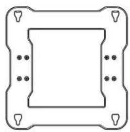
natural_image
Pure geometric diagram of a square frame with corner holes and dots, no text or symbols present.
natural_image
Technical line drawing of a mechanical bracket assembly (no text or symbols)
元件
* 請務必使用產品隨附的元件和零件。
MDF = Medium Density Fiberboard (中密度纖維板或密集板)
PW = Plywood(夹板)
③

6
natural_image
Diagram showing four different types of screw and drill bit configurations (no text or labels)使用 9X70 鑽頭鏡孔
(WMN-2370:4X25)
清潔孔洞內部
將隨附的固定器插入孔洞。
對齊可調式安裝座與孔洞,並鎖緊螺絲①。
natural_image
Technical line drawing of a rectangular frame with internal components and alignment markers (no text or symbols)natural_image
Technical line drawing of a mechanical component with two views: top view shows a curved blade, bottom view shows a bracket assembly (no text or symbols)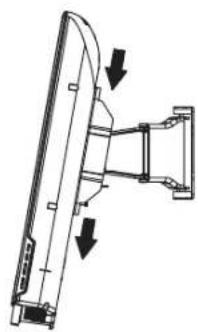
natural_image
Technical line drawing of a mechanical assembly with two downward arrows indicating motion or force directions (no text or symbols present)
natural_image
Pure technical diagram of a square frame with corner holes and mounting holes (no text or symbols)
natural_image
Technical line drawing of a mechanical bracket assembly (no text or symbols)
구성품
MDF = Medium Density Fiberboard
PW = Plywood
③
⑥
natural_image
Four-panel diagram showing different types of screw and drill bit configurations (no text or labels)natural_image
Technical line drawing of a rectangular device with internal components and mounting holes (no text or symbols)natural_image
Technical line drawing of a mechanical component with two views: one showing a curved top and the other showing a bracket with arrows indicating direction (no text or symbols)
natural_image
Diagram of a mechanical assembly with two arrows indicating direction (no text or symbols present)
natural_image
Pure geometric diagram of a square frame with corner holes and dots, no text or symbols present.