ALF 2600-2 - Mechanical chipper ATIKA - Free user manual and instructions
Find the device manual for free ALF 2600-2 ATIKA in PDF.

| Product type | Mechanical shredder (garden shredder) |
| Brand | ATIKA |
| Model | ALF 2600-2 |
| Motor | 230 V~, 50 Hz, 2600 W (S6-40%) / 2000 W (S1) |
| Cutting cylinder speed | 40 min⁻¹ |
| Maximum branch diameter | 40 mm (fresh wood) |
| Weight | 26 kg |
| Sound pressure level (LPA) | 77.8 dB(A) |
| Guaranteed sound power level (LWA) | 92 dB(A) |
| Protection class | I |
| Protection type | IP X4 |
| Mains protection | 16 A time-delay |
| Operating mode | S1 (continuous) / S6-40% (10 min cycle) |
| Collection bag | With lock and safety stop |
| Reversible rotation direction | Yes, for unblocking |
| Motor protection | Protective circuit breaker with reset button |
| Intended use | Branches, wilted garden waste (no glass, metal, plastic) |
| Wear parts | Cutting roller and counter blade (adjustable) |
| Maintenance | Clean with damp cloth, no pressure washer |
| Warranty | See enclosed warranty declaration |
Frequently Asked Questions - ALF 2600-2 ATIKA
User questions about ALF 2600-2 ATIKA
0 question about this device. Answer the ones you know or ask your own.
Ask a new question about this device
Download the instructions for your Mechanical chipper in PDF format for free! Find your manual ALF 2600-2 - ATIKA and take your electronic device back in hand. On this page are published all the documents necessary for the use of your device. ALF 2600-2 by ATIKA.
USER MANUAL ALF 2600-2 ATIKA
Original instructions – Safety instructions – Spare parts
natural_image
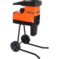
Exterior view of a gray and black ATIKA portable tool with wheels (no visible text or symbols)ALF 2600-2
D
Inbetriebnahme
natural_image
Three black-and-white illustrations: a rectangular eraser, a pen, and a textured oval (no text or symbols)89331 Burgau – Germany
Burgau, 17.11.2016
① Keep the operating instructions in a safe place for future use.
① Pass the operating instructions on to all persons who work with the machine.
You may not start to operate the machine until you have read these operating instructions, observed all the instructions given and installed the machine as described!
This machine must not be operated / used by children, persons with restricted physical, sensory or mental abilities or a lack of experience and/or know-how or by persons who are not familiar with the instructions.
The machine must not be operated by children or young people under 16 years of age.
National and local regulations may determine a different age restriction for the user.
Contents
| Extent of delivery | 11 |
| Description of the device | 11 |
| Operating times | 11 |
| Symbols on the device | 11 |
| Symbols in the operating manual | 12 |
| Proper use | 12 |
| Residual risks | 12 |
| Safety instructions | 13 |
| Assembly | 14 / 163 |
| Start-up | 14 |
| Working with the garden shredder | 15 |
| Adjusting the fixed counter blade | 16 |
| Maintenance / Cleaning / Storage | 16 |
| Operational faults | 17 |
| Technical data | 18 |
| EC Declaration of Conformity | 19 |
| Guarantee | 19 |
| Spare parts | 157 |
Extent of delivery
After unpacking, check the contents of the box
▶ That it is complete
▶ Check for possible transport damage
Report any damage or missing items to your dealer, supplier or the manufacturer immediately. Complaints made at a later date will not be acknowledged.
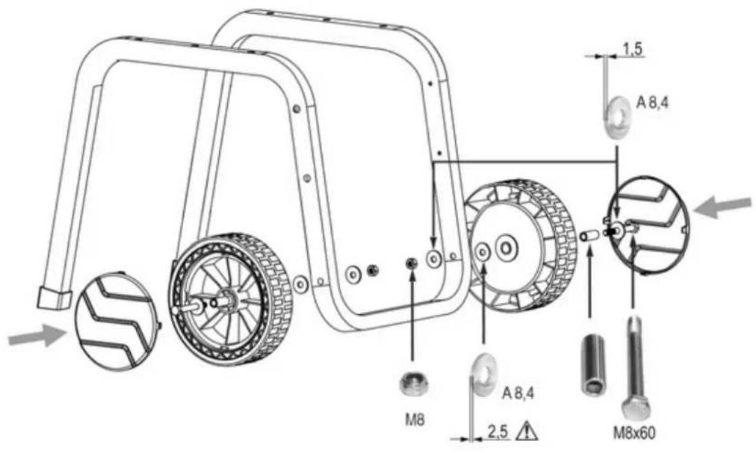
• 1 pre-assembled device unit
- 1 base frame
- 2 wheels
- 2 wheel covers
- 2 feet
- 1 screw bag
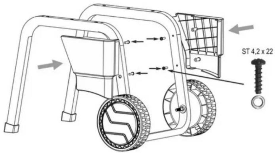
• 1 retaining basket
• 1 operating manual
• 1 warranty declaration
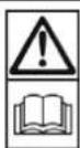
Description of the device
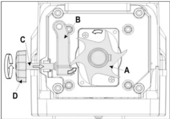
A. Direction of rotation selector switch
B. On / Off switch
C. Reset button / motor protection
D. Handle
E. Power supply plug
F. Retaining basket locking
G. Cover left
H. Hopper opening for material to be shredded
I. Upper enclosure part
J. Adjusting knob for cutting roller
K. Cover right
L. Retaining basket
M. Base frame with wheels and feet
Operating times
Please observe as well the regional regulations for noise protection.
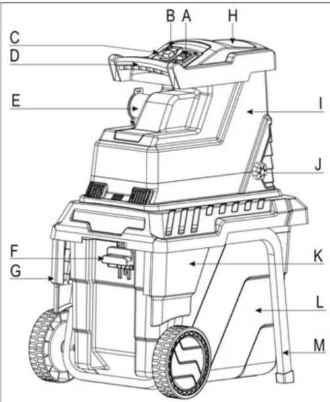
Symbols on the device
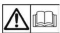
Carefully read the operating manual and the safety instructions before starting the machine and observe the instructions when operating.
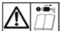
Switch off the machine and pull the mains plug before performing settings, cleaning the machine or if the cable is entangled or damaged.
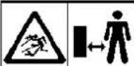 | Danger – objects may be thrown out at high speed when motor is running. Keep bystanders, pets and domestic animals out of the danger area. |
 | Wait until all machine parts have come to a dead stop before touching them. |
 | Danger – rotating blades. Keep hands and feet out of openings while machine is running. |
 | eye and ear protection. |
 | protective gloves. |
 | ct against humidity. |
 | vt use as footstep. |
| Material is cut Material is not cut | |
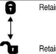 | ning basket lockedning basket unlocked |
 | product complies with European regulations fically applicable to it. |
| Electrical devices do not go into the domestic rubbish. Give devices, accessories and packaging ecofriendly recycling. | |
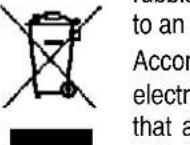 | ding to the European Directive 2012/19/EU onical and electronic scrap, electrical devices are no longer serviceable must be separately collected and brought to a facility for an environmentally compatible recycling. |
Symbols in the operating manual

Potential hazard or hazardous situation. Failure to observe this instruction may lead to injuries or cause damage to property.

Important information on proper handling. Failure to observe this instruction may lead to faults.

User information. This information helps you to use all the functions optimally.

Assembly, operation and servicing. Here you are explained exactly what to do.
Proper use
The proper use includes the shredding of
- all types of branches up to a max. diameter (depending on wood species and freshness)
- wilted, moist garden refuse that has already been stored for several days, alternating with branches
Shredding of glass, metal, plastic parts, plastic bags, stones, fabric cut-offs, roots with soil, waste without solid consistency (e.g. kitchen scraps) is explicitly excluded.
The garden shredders are suitable for private use in gardens and allotments.
As garden shredders for private gardens and allotments are considered such devices that are not applied in public facilities, parks, and sports facilities as well as in agriculture and forestry on a commercial basis.
The intended usage also includes compliance with the operating, servicing and repair conditions prescribed by the manufacturer and following the safety instructions included in the instructions.
Any other use is deemed not to be use as prescribed. The manufacturer is not liable for any type of damage resulting from this: the user bears the sole risk.
Unauthorised modifications on the garden shredder exclude a liability of the manufacturer for damages of any kind resulting from it.
Only persons who are familiarised with the device and informed about possible risks are allowed to prepare, operate and service this device. Repair works may only be carried out by us or by a customer service agent nominated by us.
Residual risks
Even if used properly, residual risks can exist even if the relevant safety regulations are complied with due to the design determined by the intended purpose.
Residual risks can be minimised if the “Safety instructions” and the “Intended usage” as well as the whole of the operating instructions are observed.
Observing these instructions, and taking proper care, will reduce the risk of personal injury or damage to the equipment.
- Risk of injury to the fingers and hands, if your hand grasps through an opening and reaches the blade unit.
- Risk of injury to the fingers and hands, when carrying out assembly work and cleaning on the blade unit.
- Injury by the chopped material spinning away near the hopper.
- Risk from electricity when using improper electrical connections.
■ Touching live parts of opened electrical components. - Impairment of hearing when working on the machine for longer periods of time without ear protection.
In addition, in spite of all the precautionary measures taken, non-obvious residual risks can still exist.
Safety instructions
Before commissioning this product, read and keep to the following advice. Also observe the preventive regulations of your professional association and the safety provisions applicable in the respective country, in order to protect yourself and others from possible injury.
i Pass the safety instructions on to all persons who work with the machine.
Keep these safety instructions in a safe place.
⚠️ Repair works on the shredder must be carried out by the manufacturer or by companies appointed by the manufacturer respectively.
■ Make yourself familiar with the equipment before using it, by reading and understanding the operating instructions.
- Do not use the machine for unsuitable purposes (see "Proper use" and "Working with the garden shredder").
■ Provide a safe standing position and keep at any time the balance. Do not lean forward. When placing material into the shredder, always stand on the same level as the machine.
- When working on slopes always make sure to have a safe standing position.
- Only move the machine at walking speed, never run with it (changing locations).
- Be observant. Attend to what you do. Start working with rationality. Do not use the device when you are tired or under the influence of drugs, alcohol or medicaments. One moment of carelessness when using the device can result in serious injuries.
■ Always wear safety goggles, work gloves and noise protection when working with the machine.
- Always wear suitable work clothing when operating the machine:
- do not wear loose-fitting clothes or jewellery; they can catch in moving parts.
- slip-proof shoes
– Trousers to protect the legs -
no loose clothing or such with hanging bands or drawstrings
-
Do not work with the device barfooted or only with thongs on your feet.
- Within his area of work the operator is responsible for third parties.
- Do not allow children to play with this machine.
- Keep children away form machine.
- Do not allow children to perform cleaning and maintenance tasks.
- Never operate the machine if other persons, especially children, or animals are in the immediate vicinity.
- The operator is responsible for accidents or hazards which occur to other persons or their properties.
■ Never leave the device unattended. - Keep your workplace in an orderly condition! Untidiness can result in accidents.
- Choose a working position alongside the equipment or behind it. Never stand near the ejection opening.
■ Never reach into the filling or ejection opening. -
Keep your face and body away from the filling opening.
-
Do not overload the machine! You work better and safer in the given performance range.
- Only operate the machine with complete and correctly attached safety equipment and do not alter anything on the machine that could impair the safety.
- Never try to bypass the interlocking function of the safety device.
- Do not alter the motor controller setting, since the rotary speed controls the safe maximum operating speed, and protects the motor and all rotating parts against damage due to excess speed. Contact the customer service in case of problems.
■ Do not operate without the funnel. - Do not modify the device or parts of the device respectively.
-
Do not hose down the device with water. (Origin of danger electric current).
■ Take into consideration environmental influences: -
Do not use the device in moist or wet ambience.
- Do not leave the machine standing in the rain.
- Do not work in bad weather conditions (e.g. rain, risk of lightning).
-
Provide for good illumination.
-
To prevent danger of injury to fingers during assembly or cleaning operations wear protecting gloves.
- Do not transport the device when the motor is running.
-
Switch off the machine and pull the mains plug from the socket and make sure that all moving parts have come to a complete standstill before:
-
attaching or removing the retaining basket
– performing maintenance and cleaning work - eliminating faults
-
checking the connection cable for damage and entanglement during operation
-
transporting
-
carrying out repair work
– leaving unattended (even during short interruptions) -
If the machine's filling funnel or ejection slot is blocked switch off the motor and disconnect the mains plug before removing material from the filling funnel or ejection slot.
- Do not touch dangerous moving parts before the machine has been isolated from the electric supply and such moving parts have come to a dead stop.
-
The power or extension cable must be separated from the supply mains immediately if they are damaged during use. Do not touch the cable before it is disconnected from mains. Do not use the machine if the cable is damaged or worn.
■ Check the machine for possible damage: -
Before further use of the machine the safety devices must be checked carefully for their proper and intended function.
- Check whether movable parts function perfectly and do not stick or whether parts are damaged. All parts must be correctly installed and fulfil all conditions to ensure perfect operation of the machine.
- Damaged safety devices and parts must be properly repaired or exchanged by a recognized, specialist workshop; insofar as nothing else is stated in the instructions for use.
– Damaged or illegible safety labels have to be replaced.
GB
- Store unused equipment in a dry, locked place out of the reach of children.
- Store the machine in a place where fuel vapours cannot come close to open flames or sparks. Always allow the machine to cool down before storing it.
- Maintain the machine with care and keep it clean.

Electrical safety
■ Design of the connection cable according to IEC 60 245 (H 07 RN-F) with a core cross-section of at least
- 1.5 mm ^2 for cable lengths up to 25 m
- 2.5 mm ^2 for cable lengths over 25 m
- Long and thin connection lines result in a potential drop. The motor does not reach any longer its maximal power; the function of the device is reduced.
- Plugs and coupler outlets on connection cables must be made of rubber, plasticised PVC or other thermoplastic material of same mechanical stability or be covered with this material.
- The connector of the connection cable must be splash-proof.
- When running the connection line observe that it does not interfere, is not squeezed, bended and the plug connection does not get wet.
- Keep the extension cable away from dangerous moving parts to prevent damages to the cable, which can result in touching live parts.
■ Wind off completely the cable when using a cable drum.
- Do not use the cable for purposes for which it is not meant. Protect the cable against heat, oil and sharp edges. Do not use the cable to pull the plug from the socket.
- Regularly check the extension cables and replace them if they are damaged.
- Please note that no damage cable must be connected to the power supply and no damaged cable may be touched before it was separated from the power supply since damaged cables may touch active components.
- Do not use any defective connection cables.
- When working outdoors, only use extension cables especially approved and appropriately labelled for outdoor use.
- Do not set up any provisional electrical connections.
■ Never bypass protective devices or deactivate them.
- Only hook up the machine by means of a fault-current circuit breaker (30 mA).

The electrical connection or repairs to electrical parts of the machine must be carried out by a certified electrician or one of our customer service points. Local regulations – especially regarding protective measures – must be observed.

If the power cord (if available) of this machine is damaged, it must be replaced by a specific power cord that can be purchased from the manufacturer or customer service.

Repairs to other parts of the machine must be carried out by the manufacturer or one of his customer service points.

Use only original spare. Accidents can arise for the user through the use of other spare parts. The manufacturer is not liable for any damage or injury resulting from such action.
Behaviour in an emergency situation
- Initiate all required first aid measures suited for the injury and seek qualified medical advice as quickly as possible.
- Protect the injured person against further injuries and immobilise the injured person.
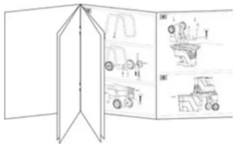
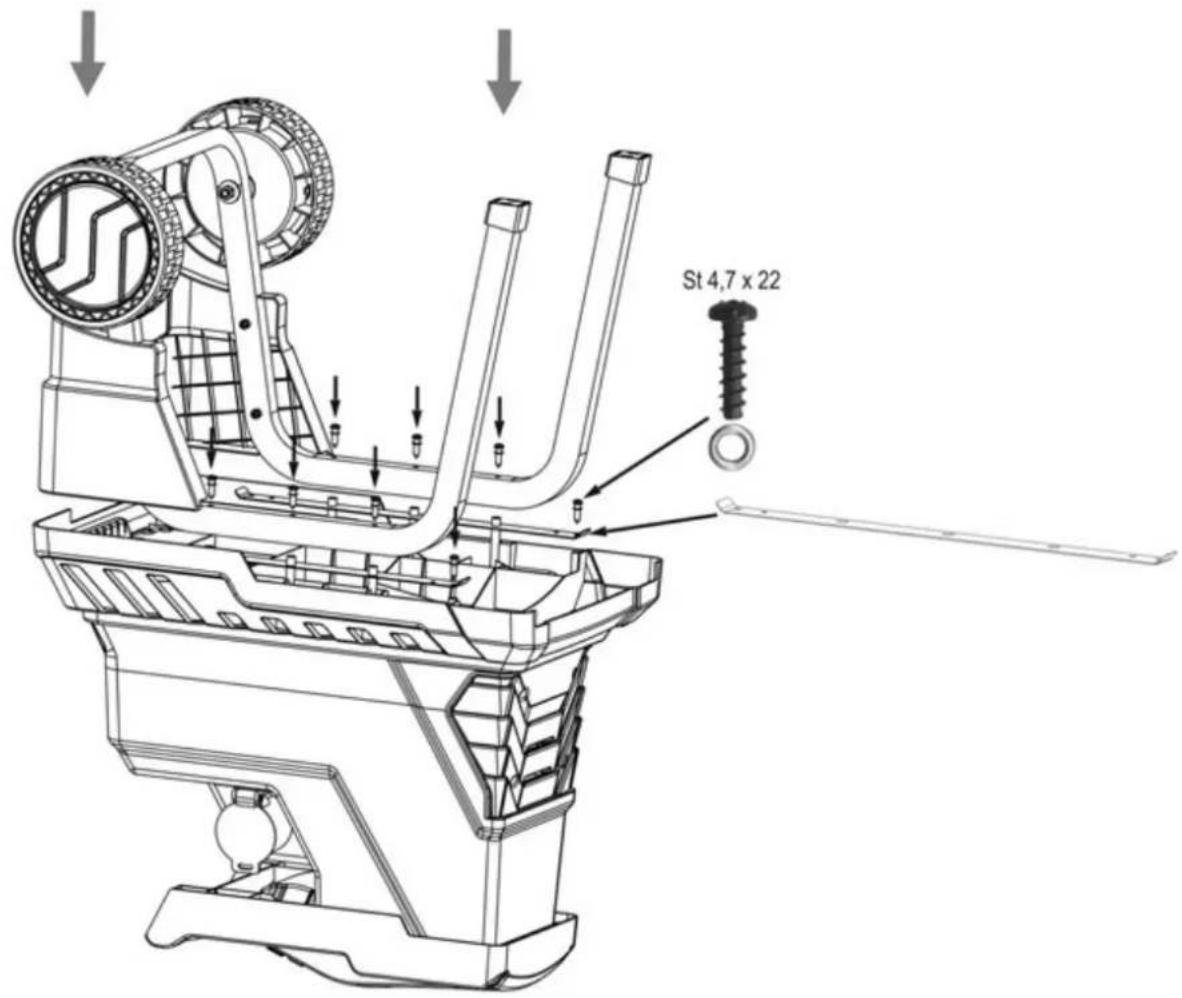
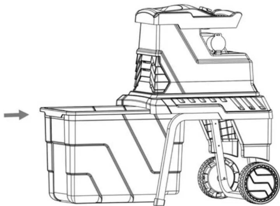
Assembly
See page 163
Start-up
- Check that the machine is completely and correctly assembled.
- Make sure before starting the machine that the feeding device (the filling hopper) is empty.
- To avoid toppling, place the shredder on a firm horizontal surface.
- Avoid working on moist surfaces. A moist surface affects the safe footing of the machine and increases the risk of accidents.
- Do not use this machine on a paved or gravel-covered area on which thrown out material can cause injury.
■ Do not work directly near swimming pools or garden ponds. - The machine should only be operated in the open. Always maintain a safe distance (at least 2 m) from walls or other fixed objects.
- Do not operate the machine in bad weather conditions.
■ Before each use, - Check the supply / extension cable for damages (cracks, cuts or the like) or ageing (brittleness).
⚠️ Do not use defective supply or extension cables. - Check there are no damage at the machine (see safety instructions).
- Make sure that the shredder tool is neither worn out nor damaged and that it is properly secured.
- Check that all screws, nuts and bolts as well as other fasteners are securely tightened.
- Check that covers, deflectors and protective shields are on their correct position and in good working condition.
Mains connection
- Compare the voltage given on the machine model plate e.g. 230 V with the mains voltage and connect the machine to the relevant and properly earthed plug.
- Connect the machine via a circuit breaker switch (residual-current-operated circuit switch) 30 mA.
- Always use three-conductor extension cables with connected earthing conductor and sufficient cross section.
Mains fuse
2600 W
16 A time-lag

Electrical mains supply impedance
When conditions in the electrical mains supply are unfavourable, voltage reductions for short periods can occur during the process of turning on the equipment, which can adversely affect other equipment (e.g., the flickering of a lamp).
No breakdowns are to be expected if the maximum, electrical mains supply impedances given in the table are met.
| Power consumption P_1 (W) | Electrical mains supply impedance Zmax ( ) |
| 2600 | 0.268 |
On / Off switch
Do not use any device where the switch can not be switched on and off. Damaged switches must be repaired or replaced immediately by the customer service.
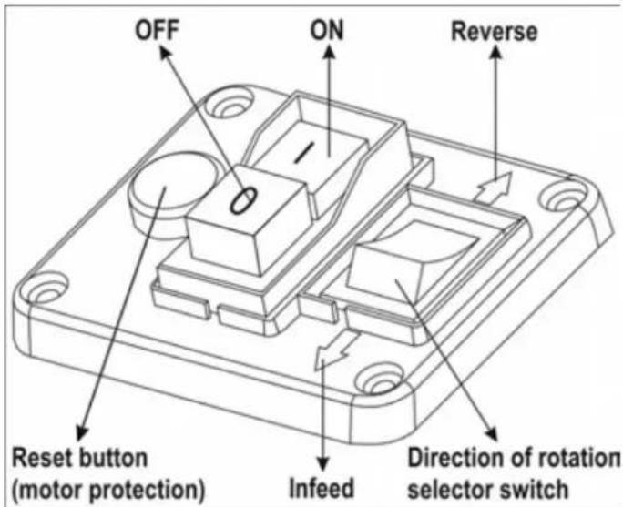

Switch on
Press the green button .1

Switch off
Press the red button.

Restart protection in case of power failure
In case of a power failure, the device switches off automatically (zero-voltage initiator). To restart, press the green button again.

Motor protection
The motor is equipped with a safety switch and switches off automatically when overloaded. After a cooling-down break (approx. 5 min), the motor may be restarted. Press the
- reset button (motor protection)
- green button ☐ to restart.
Direction of rotation selector switch
⚠️ Only actuate the direction of rotation selector switch while the shredder is switched off.
Position

The material is drawn in by the cutting roller and shredded.
Position

The blades operate in the opposite direction and jammed material is released.
Keep depressing the green button of the on/off switch once you have placed the direction of rotation selector switch into the position. The cutting roller is placed into the opposite direction. If you release the on/off switch, the shredder automatically stops.
Hints
● Large objects or pieces of wood may be removed after the shredder has been operated several times both in cutting and in release direction.
- Use a tamper or hook to remove jammed objects from the hopper or ejection slot.
⚠️ Always wait until the shredder has come to a complete standstill before restarting it.
Retaining basket
The integrated retaining basket is equipped with a locking lever and a safety cut-out device.
Power off the device before attaching or removing the retaining basket.
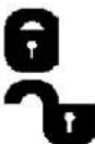
→ Retaining basket locked and fixed connected to the device.
→ Retaining basket unlocked and disconnected from the device. The device cannot be powered up.
① When the retaining basket is unlocked while the device is operating the device is automatically cut out.
Working with the garden shredder
- Choose a working position alongside the equipment or behind it. Never stand near the ejection opening.
■ Provide a safe standing position and keep at any time the balance. Do not lean forward. When placing material into the shredder, always stand on the same level as the machine.
■ Always keep away from the ejection area when starting the machine. - Longer material that is protruding from the device could spring back when it is drawn in by the blades! Observe safety distance!
■ Never reach into the filling or ejection opening. - Keep your face and body away from the filling opening.
- Never place hands, other parts of the body or clothing into the filler funnel, ejection channel or in the vicinity of other moving parts.
- Check before powering the device up that:
— no material residues are in the filling hopper,
— the retaining basket is locked.
- Do not tilt or transport the machine (relocation) while the motor is running.
GB
- Make sure that the motor is free from waste material and other material accumulation to protect it against damage and to prevent fire.
- When filling, be careful that no pieces of metal, stones, bottles or other objects unintended for processing, enter the filling hopper.
■ Power off the device before attaching or removing the retaining basket. - Immediately switch off the equipment and allow it to come to a stop, if foreign objects enter the filling hopper or if the equipment starts to make unusual noises or vibrates. Remove the mains plug and carry out the following checks:
– inspect for damage,
– replace or repair damaged parts,
– check the equipment and tighten loose parts.

You must not repair the equipment yourself if you are authorized to do so.

What can I shred?
Yes:
- all types of branches up to a max. diameter, depending on wood species and freshness.
- withered garden refuse which has lain a number of days. Only shred in alternation with branches.
No:
- glass, metal, plastic, plastic bags, stones, cloth, roots with soil
- refuse which does not have a solid consistency, e. g. kitchen waste

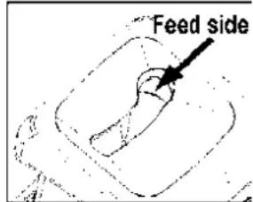
Special tips on shredding:
➢ Always fill the material to be shredded into the filling hopper from the right.
➢ Branches, twigs and wood should be broken down immediately after they have been cut
- material of this kinds gets very hard when it is dry, and the maximum allowed branch diameter to be processed has to be reduced.
➢ Remove any side shoots from branches with a large number of twigs.
How to shred garden waste with hight water content and a tendency to clog
- to prevent the machine from clogging, alternate waste with wood containing material.
Do not allow the shredded material to pile up too high in the area of the ejection opening. This can lead to shredded material blocking the ejection channel, and backing up to the filler opening. Empty the retaining basket on a regular basis.
Clean out the filler opening and ejection channel thoroughly if the machine becomes blocked. Before doing this, switch the motor off and disconnect the machine from the mains power supply.
➢ Please do not exceed the maximum branch diameter specified (cutting fresh wood) for your appliance (∅ see "Technical data"). Depending on the wood's nature and freshness the maximum branch diameter the machine can process may be smaller.
The cutter automatically draws the shredding material into the machine through the slow rotation of the cutting rollers.
➢ Automatic switch-over in the direction of rotation:
If the unit suddenly clogs, the blades may start to turn in the opposite direction and push the shredded material back out.
- Switch off unit
— Wait until the blades come to a standstill - Switch unit back on and use material which is easier to process.
If the machine is overloaded, a protective motor switch ensures that the machine turns itself off automatically.
— Turn the shredder on again after about 5 minutes.
- If you cannot turn on the machine after this waiting time refer to „Operational faults“.
Adjusting the fixed counter blade
It is possible to adjust the counter blade (B) at the cutting roller (A) free of clearance. For an effective operation, an as small as possible clearance should be maintained.
Soft material or wet branches may tear instead of being cut. A counter blade that is worn after repeated use may also lead to this problem.
Setting the clearance.
Switch on the device.
There is an adjustment device on the right hand side of the plastic housing. To adjust the distance turn the adjusting knob (D) clockwise so that the screw (C) moves toward the cutting roller. Turn until fine aluminium chips are falling from the ejection slot.
Maintenance / Cleaning / Storage
• Each time before starting maintenance work:
- Switch off the motor and pull out the mains plug.
- Allow the machine to cool down.
- Wear protective gloves to prevent injury.
When the machine is stopped for purpose of maintenance, storage or accessory replacement make sure that the energy source is isolated and the mains plug is disconnected. Make sure that all movable parts are stationary and the key (if applicable) is removed. Allow the machine to cool down before maintenance, adjustment etc.
The cutters will not come to a standstill immediately after cut-off. Before starting any service work wait until all parts are stationary.
When performing maintenance operations on the cutting tool be aware that it can still move due to the start mechanism even if the motor does not run by the cover interlocking.
Be sure to have removed any tools from the machine after completion of service work.
- Generally garden shredders require little maintenance. To maintain their efficiency and a long life, observe the following:
- Keep vent slits clean and free from obstructions.
- Check the locking screws (tighten where necessary).
– Clean the device after shredding.
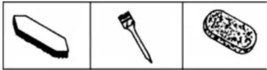
To clean your product only use a warm moist cloth and a soft brush.
Never use cleaning agents or solvents. Otherwise the device may be damaged irreversibly. Plastic parts may be corroded by chemicals.
natural_image
Three simple line drawings of erasers, a brush, and a textured object (no text or symbols)- Do not clean the machine with running water or high-pressure cleaners.
- After each operation treat bare metal parts with an environment-compatible biodegradable spray oil to protect them against corrosion.
- the cutting roller and shaving plate are expendable parts, though with normal use and correct adjustment they have a service life of many years.
- Replace worn and damaged single parts as a whole set to prevent any unbalance.
Operational faults
Before each fault elimination:
- Switch off device.
— Wait for standstill of the device.
— Pull out mains plug.
| Fault | Possible cause | Remedy |
| Motor does not start | No power supply | Check fuses |
| Mains cable defective | have these checked (electrician) | |
| Machine overloaded (motor protection) | Allow the device to cool down. Press the 1. reset button (motor protection) 2. green button ☐ to restart. | |
| Retaining basket unlocked (safety cut-out device of the retaining basket has tripped) | Lock the retaining basket ☑ | |
| Motor hums but does not start | Cutting roller blocked | Switch off the device. Turn the direction of rotation selector switch into position ↑Switch on device until the jam has been cleared. Switch device off again. Turn back the direction of rotation selector switch to position ↓. |
| Capacitor faulty | Bring machine to manufacturer or authorised workshop for repair | |
| Shredding material is not drawn into the shredder | The cutting roller is running in reverse. Wrong switch position | Switch off device and switch over direction of rotation selector switch. |
| Shredding material caught in funnel | Switch off device. Switch the direction of rotation selector switch into position ↑. Switch on device to release the material to be shredded, remove any foreign matter. Switch off device again. To continue work, place the direction of rotation selector switch back into position ↓. Re-insert thick branches so that the cutting roller does not re-engage in existing notches. | |
| Shredding material is not drawn into the shredder | Shredding material too soft or wet | Push down with a branch and shred |
| Cutting roller worn | Adjust fixed counter blade as described under „adjusting the fixed counter blade“. In case of severe wear, replace cutting roller.Have the cutting roller replaced by the customer service. | |
| Shredding material not cut cleanly. | Fixed counter blade not adequately adjusted. | Adjust fixed counter blade. |
| Device starts but blocks under as slight load and switches off via protective motor switch. | Extension cable too long or cross-section to small.Socket too far from mains supply and cross-section of mains cable too small. | Extension cable at least 1.5 mm^2 , maximum 25 m long. If a longer cable is used, minimum cross-section 2.5 mm^2 . |
In case of further failures please contact our customer service.
Technical data
| Type / Model | ALF 2600-2 |
| Year of construction | see last page |
| Motor | AC-Motor 230 V~, 50 Hz, 2800 rpm |
| Motor rating P1 S6 - 40 % | 2600 W |
| Motor rating P1 S1 | 2000 W |
| Rotational speed cutting roller | 40 min ^-1 |
| ON/OFF-switch with | overload protection; cutting and reverse function, zero-voltage initiator |
| Weight | 26 kg |
| Sound pressure level at work LPA (measured to 2000/14/EC) | 77.8 dB (A) |
| Measured sound power level LWA (measured to 2000/14/EC) | 91.8 dB (A)K = 0.5 dB (A) |
| Guaranteed sound power level LWA (measured to 2000/14/EC) | 92 dB (A) |
| Max. branch diameter (only for freshly cut wood) | ∅ max. 40 mm |
| Safety class | I |
| Protection class | IP X4 |
| Mains fuse | 16 A time-lag |
| Operating mode: | S1 | S 6 – 40 % |
| Continuous operation | Continuous intermittent operationFor 10 min.:4 min. continuous operation6 min. operation at no or low load |
EC Declaration of Conformity
No. (S-No.): 15393
according to EC directive: 2006/42/EC
We,
ATIKA GmbH
Josef-Drexler-Str. 8, 89331 Burgau - Germany
herewith declare under our sole responsibility that the product
Gartenhäcksler (Garden Shredder) type ALF 2600-2
Serial number: 000001 - 020000
is conform with the above mentioned EC directives as well as with the provisions of the guidelines below:
2014/30/EU, 2011/65/EU and 2000/14/EC+2005/88/EG.
Following harmonized standards have been applied:
EN 60335-1:2012+A11; EN 50434:2014; EN 62233:2008; EN 55014-1:2006/A2:2011; EN 55014-2:2015; EN 61000-3-2:2014; EN 61000-3-11:2000
Conformity assessment procedure: 2000/14/EC - Appendix V and 2005/88/EC.
Measured level of the acoustic output L_WA 91.8 dB (A).
Guaranteed level of the acoustic output L_WA 92 dB (A).
Duly authorised person for the compilation of technical documents:
ATIKA GmbH – Technical department – Josef-Drexler-Str. 8 – 89331 Burgau – Germany
i.A.
Burgau, 17.11.2016

Guarantee
Please observe the enclosed terms of guarantee.
F
Mise en service
natural_image
Three black-and-white illustrations: eraser, pen, and textured object (no text or symbols)Пускане в действие
natural_image
Three simple 3D-rendered objects: a rectangular block, a pen-like tool, and a textured oval object (no text or symbols)Uvedení do provozu
natural_image
Three black-and-white illustrations of erasers: a rectangular block, a pen, and a textured rectangular object (no text or symbols)Ibrugtagning
natural_image
Three black-and-white illustrations: a rectangular eraser, a pen, and a textured rectangular object (no text or symbols)Käyttöönotto
natural_image
Three simple line drawings: eraser, pen, and textured object (no text or symbols)Üzembe helyezés
natural_image
Three simple line drawings of erasers: a rectangular block, a pen, and a textured rectangular block (no text or symbols)Puštanje u pogon
natural_image
Three black-and-white illustrations of erasers: a rectangular block, a pen, and a textured rectangular block (no text or symbols)- Vrtnu sjeckalicu ne čistite tekućom vodom niti uređajima za čišćenje pod visokim tlakom.
Messa in funzione
natural_image
Three black-and-white illustrations: eraser, nail, and textured stone (no text or symbols)Ibruktaking
Ingebruikname
natural_image
Three black-and-white illustrations: eraser, pen, and textured object (no text or symbols)Uruchomienie
natural_image
Three black-and-white illustrations: a rectangular block, a pen-like tool, and a textured oval (no text or symbols)89331 Burgau – Germany
natural_image
Three black-and-white illustrations: a rectangular block, a pen, and a textured oval (no text or symbols)conform directivei 2006/42/UE
Prin prezenta, noi
ATIKA GmbH
Josef-Drexler-Str. 8, 89331 Burgau - Germany
Conformity assessment procedure:
Ввод в эксплуатацию
natural_image
Abstract line drawing with a curved shape and an arrow, no text or symbols presentIdrifttagning
natural_image
Three simple line drawings of erasers, a pen, and a textured object (no text or symbols)89331 Burgau – Germany
i.A.
Burgau, 17.11.2016

Garanti
natural_image
Three black-and-white illustrations: a rectangular block, a pen, and a textured oval (no text or symbols)A. Stikalo za smer vitja
B. Stikalo za vklop/izklop
C. Povratni gumb / Zaščitje motora
D. Ročaj
E. Vtič
F. Zapah lovilne košare
G. Pokrov levo
H. Žrelo za rezalno blago
I. Gornji del ohišjal
J. Nastavni gumb za rezalni valj
K. Pokrov desno
L. Lovilna košara
M. Podvozje s kolesi in nogami
Obratovalni časi
Zagon
2000/14/ES - Dodatek V in 2005/88/ES.
Izmerjen nivo hrupa LWA 91,8 dB (A).
Garantirani nivo hrupa LWA 92 dB (A).
natural_image
Technical line drawing of a U-shaped metal frame with two mounting holes and directional arrows indicating assembly or movement (no text or symbols)2
3
4
5
natural_image
Technical line drawing of a mechanical device with wheels and a ramp, showing no text or symbols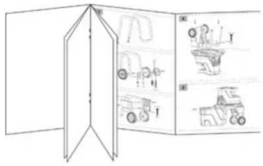
D
Baujahr
GB
Year of construction
F