DW075 - Laser pointer DEWALT - Free user manual and instructions
Find the device manual for free DW075 DEWALT in PDF.

| Product Type | Rotary Laser Level |
| Brand | DEWALT |
| Model | DW075 |
| Laser Class | 3R |
| Laser Power | 5 mW, 600-680 nm |
| Accuracy | ± 0.2 mm/m |
| Self-Leveling Range | ± 5° |
| Protection Rating | IP54 |
| Power Source | 2 LR20 batteries (D type) |
| Weight (without batteries) | 2.0 kg |
| Operating Temperature | -5°C to +50°C |
| Mounting Thread | 5/8" - 11 |
| Package Contents | Rotary laser, 2 LR20 batteries, wall mount, remote control, visual card, laser glasses, detector, 2 9V batteries, detector mount, case, grade rod, tripod, manual |
| Maintenance and Cleaning | Clean with a soft, dry cloth. Do not use solvents. Clean the lens with a damp cotton swab. |
| Safety | Do not look directly into the beam. Use only DEWALT accessories. Keep out of reach of children. |
| Warranty | 1 year against material and workmanship defects |
Frequently Asked Questions - DW075 DEWALT
User questions about DW075 DEWALT
0 question about this device. Answer the ones you know or ask your own.
Ask a new question about this device
Download the instructions for your Laser pointer in PDF format for free! Find your manual DW075 - DEWALT and take your electronic device back in hand. On this page are published all the documents necessary for the use of your device. DW075 by DEWALT.
USER MANUAL DW075 DEWALT
English (original instructions)
EAAnviKa (eT4paaan aio npi npwirotuies oynies) 130
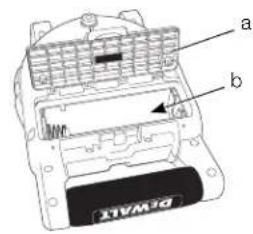
Figure 1
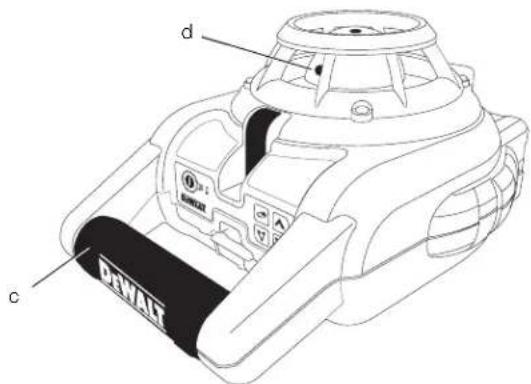
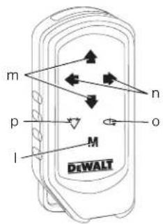
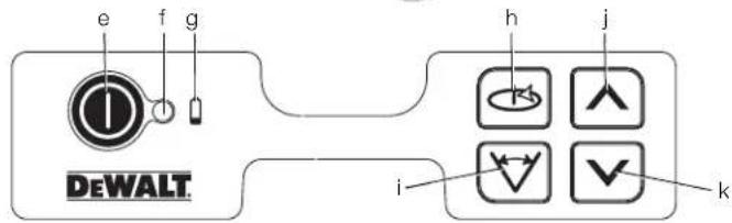
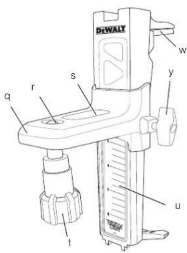
Figure 2
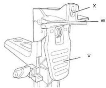
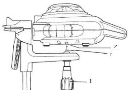
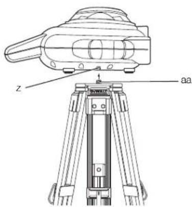
Figure 3
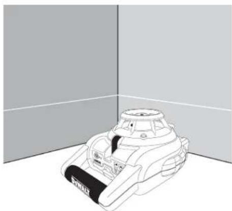
Figure 4
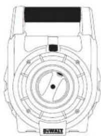
Figure 6Figure 5
A

B

Figure 7
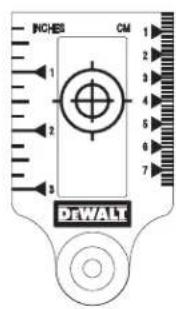
Figure 8
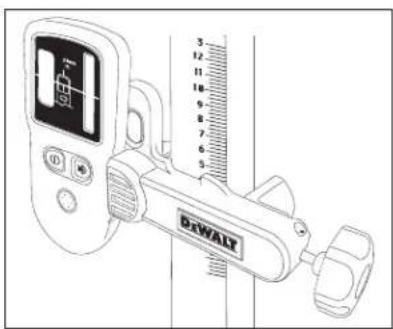
Figure 9
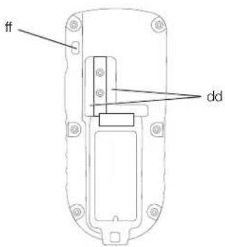
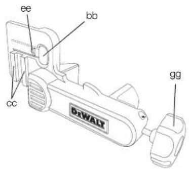

Figure 10
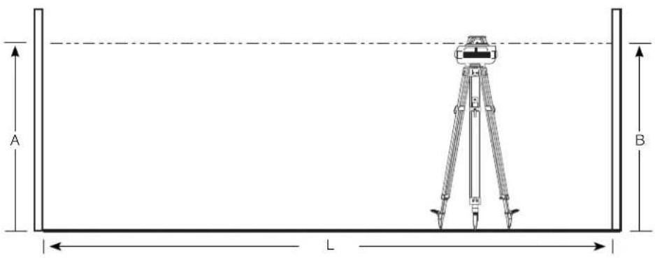
Figure 11
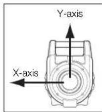
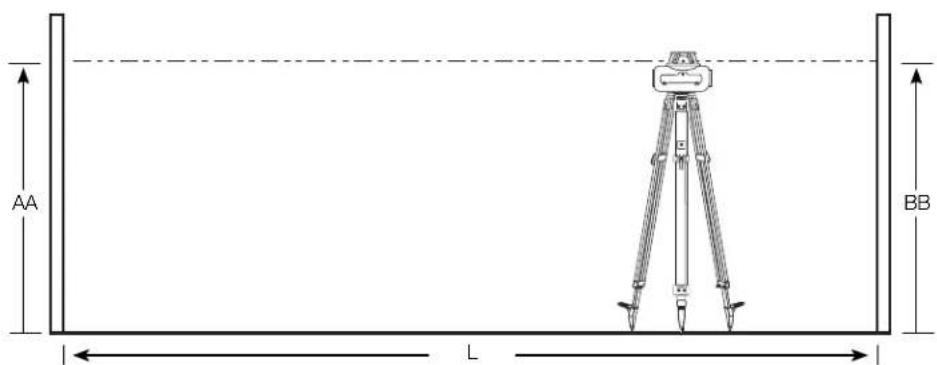
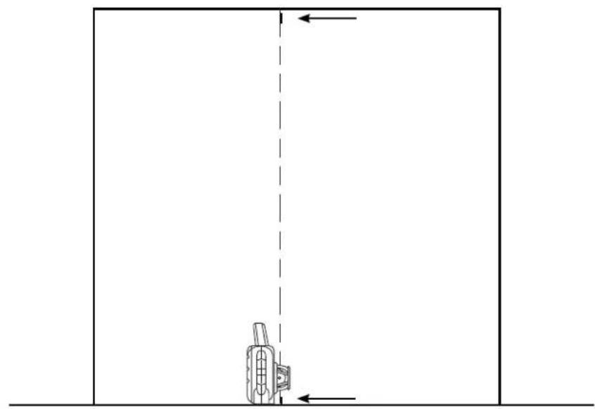
Figure 12
DANSK
ROTERENDE LASER DW075
Tillykke!
MANUEL HOVEDROTATION (FIG.1)
FORSIGHTIG: Sorg for, at skinner
eller vinklen sidder ordentigt fast, for lasevaterpasset monteres pa en vaegskinne eller loftsvinkel.
- Placer laseren pa monteringssoklen (q), sa hullet (z) i bunden at laseren flugter med hullet (r) i monteringssoklen. Placer den bagerste gummifod i monteringsssoklens abning (s). Drej pa monteringesgrebet (t) for at fastgore laseren.
- Tryk pa klemmegrebet (v) for at abne klemmekaebeme (w), mens vaegbeslagets maleskala (u) vender ud mod dig.
- Placer klemmekaebeme (w) rundt om vægskinnen aller loftsvinklen og slip klemmegrebet (v) for at lukke klemmekaeberne omkring skinner. Sorg for, at vaegbeslaget sidder fast, for du fortsaelter.
FORIGTIG: Brug altid en
KONSTRUKTIONSMÄLEPIND (FIG. 6)
You have chosen a DEWALT laser. Years of experience, thorough product development and innovation make DEWALT one of the most reliable partners for professional power tool users.
Technical Data
| DW075 | ||
| Voltage | V | |
| 2 x LR20 (D-size) | ||
| Type | ||
| Rotary speed min | -1 | 0-600 |
| Laser class 3R | ||
| Protection class IP54 | ||
| Accuracy | mm/m | ± 0.2 |
| Self-leveling range | ° | ± 5 |
| Operating temperature | °C | -5 to +50 |
| Receptacle thread | 5/8"-11 | |
| Weight (without battery pack) | kg | 2.0 |
Definitions: Safety Guidelines
The definitions below describe the level of severity for each signal word. Please read the manual and pay attention to these symbols.

DANGER: Indicates an imminently hazardous situation which, if not avoided, will result in death or serious injury.

WARNING: Indicates a potentially hazardous situation which, if not avoided, could result in death or serious injury.

CAUTION: Indicates a potentially hazardous situation which, if not avoided, may result in minor or moderate injury.
CAUTION: Used without the safety alert symbol indicates a potentially hazardous situation which, if not avoided, may result in property damage.

Denotes risk of electric shock.

Denotes risk of fire.
Safety Instructions for Lasers

WARNING! Read and understand all instructions. Failure to follow all instructions listed below may result in electric shock, fire and/or serious personal injury.
SAVE THESE INSTRUCTIONS
- Do not operate the laser in explosive atmospheres, such as in the presence of flammable liquids, gases or dust. Power tools create sparks which may ignite the dust or fumes.
- Use the laser only with the specifically designated batteries. Use of any other batteries may create a risk of fire.
- Store idle laser out of reach of children and other untrained persons. Lasers are dangerous in the hands of untrained users.
- Use only accessories that are recommended by the manufacturer for your model. Accessories that may be suitable for one laser, may create a risk of injury when used on another laser.
- Tool service MUST be performed only by qualified repair personnel. Repairs, service or maintenance performed by unqualified personnel may result in injury. For the location of your nearest authorised DEWALT repair agent, refer to the list of authorised DEWALT repair agents on back of this manual or visit www.2helpU.com on the Internet.
- Do not use optical tools such as a telescope or transit to view the laser beam. Serious eye injury could result.
- Do not place the laser in a position which may cause anyone to intentionally or unintentionally stare into the laser beam. Serious eye injury could result.
- Do not position the laser near a reflective surface which may reflect the laser beam toward anyone's eyes. Serious eye injury could result.
- Turn the laser off when it is not in use.
Leaving the laser on increases the risk of staring into the laser beam. - Do not operate the laser around children or allow children to operate the laser. Serious eye injury may result.
- Do not remove or deface warning labels. If labels are removed, user or others may inadvertently expose themselves to radiation.
ENGLISH
- Position the laser securely on a level surface. Damage to the laser or serious injury could result if the laser falls.
- Dress properly. Do not wear loose clothing or jewellery. Contain long hair. Keep your hair, clothing and gloves away from moving parts. Loose clothing, jewellery or long hair can be caught in moving parts. Air vents often cover moving parts and should also be avoided.

WARNING: Use of controls or adjustments or performance of procedures other than those specified herein may result in hazardous radiation exposure.
WARNING! DO NOT DISASSEMBLE THE ROTARY LASER. There are no user serviceable parts inside. Disassembling the rotary laser will void all warranties on the product. Do not modify the product in any way. Modifying the tool may result in hazardous laser radiation exposure.
Additional Safety Instructions for Lasers
- This laser complies with class 3R according to DIN EN 60825-1:2007-11 (max 5 mW, 600-680 nm). Do not replace a laser diode with a different type. If damaged, have the laser repaired by an authorised repair agent.
- Only qualified and trained persons are allowed to install, adjust and operate the laser equipment. Areas in which class 3R lasers are used have to be posted with an appropriate laser warning sign.
- Do not use the laser for any purpose other than projecting laser lines.
- Before first use, check that the safety warnings on the label have been formulated in your language. Do not use the tool if it does not carry the warnings in your language!
- As the beam of a class 3R laser provides high visibility over longer distances, the potential risk of damage to the eye remains unchanged within the radius of application.
- Always set up the tool at a position where the laser beam cannot cross any person at eye level. Be extra alert for the presence of stairs and specular surfaces.
Residual Risks
The following risks are inherent to the use of these machines:
Injuries caused by staring into laser beam.
Markings on Tool
The following pictographs are shown on the tool:


Read instruction manual before use.

Laser warning.

Class 3R laser.

Protection class: IP54.
DATE CODE POSITION
Date Code, which also includes the year of manufacture, is printed on the bottom of the laser near the mounting threads.
Example:
2010 XX XX
Year of Manufacture
Important Safety Instructions for Battery
WARNING: Batteries can explode, or leak, and can cause injury or fire. To reduce this risk:
- Carefully follow all instructions and warnings on the battery label and package.
Always insert batteries correctly with regard to polarity (+ and -), marked on the battery and the equipment. - Do not short battery terminals.
- Do not charge batteries.
- Do not mix old and new batteries. Replace all of them at the same time with new batteries of the same brand and type.
- Remove dead batteries immediately and dispose of per local codes.
- Do not dispose of batteries in fire.
- Keep batteries out of reach of children.
- Remove batteries if the device will not be used for several months.
Batteries (fig. 1)
BATTERY TYPE
The DW075 operates on two LR20 (D-size) batteries.
Package Contents
The package contains:
1 Rotary laser
2 LR20 (D-size) batteries
1 Wall mount
1 Remote control
1 Target card
1 Pair of laser enhancement glasses
1 Detector
2 6LR61 (9V) batteries
1 Detector clamp
1 Kitbox
1 Grade rod
1 Tripod
1 Instruction manual
- Check for damage to the tool, parts or accessories which may have occurred during transport.
Take the time to thoroughly read and understand this manual prior to operation.
Description (fig. 1, 2)
WARNING: Never modify the power tool or any part of it. Damage or personal injury could result.
INTENDED USE
The DW075 rotary laser has been designed to project laser lines to aid in professional applications. The tool can be used both inside and outside for horizontal (level) and vertical (plumb) alignment. The tool can also produce a stationary laser dot that can be directed manually to establish or transfer a mark. The applications range from drop-ceiling installation and wall layout to foundation leveling and deck building.
DO NOT use under wet conditions or in presence of flammable liquids or gases.
This laser is a professional tool. DO NOT let children come into contact with the unit. Supervision is required when inexperienced operators use this laser.
LASER (FIG. 1)
a. Battery compartment
b. Battery icon
c. Carrying handle
d. Rotary laser head
e. Power button
f. Power/low battery LED indicator
g. Low battery icon
h. Speed/rotation button
i. Scan mode button
j. Directional arrow: up
k. Directional arrow: down
REMOTE CONTROL (FIG. 1)
- Manual mode button
m. Directional arrows: up/down
n. Directional arrows: left/right
o. Speed/rotation button
p. Scan mode button
WALL MOUNT (FIG. 2)
q. Mounting base
r. Base mounting hole
s. Base mounting slot
t. Mounting knob
u. Scale
v. Clamp lever
w. Clamp jaws
x. Mounting hole
y. Locking knob
Unpacking
FITTING THE WARNING LABEL
The safety warnings on the label shown on the laser must be formulated in the language of the user.
For that purpose, a separate sheet of self-adhesive labels has been supplied with the tool.
WARNING: Check that the safety warnings on the label have been formulated in your language.
The warnings should read as follows:
LASER RADIATION AVOID DIRECT EYE EXPOSURE CLASS 3R LASER PRODUCT
If the warnings are in a foreign language, proceed as follows:
- Remove the required label from the sheet.
ENGLISH
-
Carefully place the label over the existing label.
-
Press the label in place.
ASSEMBLY
Inserting and Removing the Batteries (fi g. 1)
NOTE: This tool is powered by two LR20 (D-size) batteries.
INSTALLING THE BATTERY PACK
- Lift up the battery compartment cover (a) as shown in Figure 1.
- Insert two fresh LR20 (D-size) batteries in the battery compartment. Place the batteries according to the embossed icon (b) inside of the compartment.
Setting Up the Laser
The laser facilitates various set-ups, making it useful for several applications.
MANUAL HEAD ROTATION (FIG. 1)
The laser is designed with a protective alloy cage around the rotary head (d) to prevent accidental damage from work site activities. You can still access the rotary head and manually direct the beam to establish or transfer a mark.
WALL SET-UP (FIG. 2)
The wall mount is used for mounting the laser to a wall track to aid in drop ceiling installation and other specialty leveling projects.

CAUTION: Before attaching the laser level to wall track or ceiling angle, be sure that the track or angle is properly secured.
- Place the laser on the mounting base (q) aligning the hole (z) on the bottom of the laser with the hole (r) in the mounting base. Place rear rubber foot into the base mounting slot (s). Turn the mounting knob (t) to secure the laser.
- With the wall mount measuring scale (u) facing you, push the clamp lever (v) in to open the clamp jaws (w).
- Position the clamp jaws (w) around the wall track or ceiling angle and release the clamp lever (v) to close the clamp jaws on the track. Be sure that the wall mount is secure before proceeding.

CAUTION: Always use a ceiling wire hanger or equivalent material, in addition to the wall mount clamp locking knob.
to help secure the laser level while mounting it to a wall. Thread the wire through the handle of the laser level. DO NOT thread the wire through the protective metal cage. Additionally, screws may be used to fasten the wall mount directly to the wall as a back-up. A screw hole (x) is located at the top of the wall mount.
- The tool can be adjusted up and down to the desired offset height for working. To change the height, loosen the locking knob (y) located on the side of the wall mount to move the laser level up and down to the desired height. Support the mounting base when adjusting the height.
- Use the wall mount measuring scale (u) to pinpoint your mark.
NOTE: The DEWALT target card is marked at 38mm (1 - 1 / 2^) therefore, it may be easiest to set the offset of the laser to 38~mm (1 - 1 / 2^*) below the track.
- Once you have positioned the laser at the desired height, tighten the locking knob (y) to maintain this position.
TRIPOD SET-UP (FIG. 3)
- Position the tripod securely and set it to the desired height.
- Make sure that the top of the tripod is roughly level. The laser will self-level only if the top of the tripod is within ± 5^ of level. If the laser is set up too far out of level, it will beep when it reaches the limit of its leveling range. No damage will be done to the laser, but it will not operate in an "out of level" condition.
- Secure the laser to the tripod by screwing the threaded knob (aa) on the tripod into the female thread (z) on the bottom of the laser.
NOTE: Be sure that the tripod you are working with has a 5/8"–11 threaded screw to ensure secure mounting.
- Tum the laser on and adjust the rotation speed and controls as desired.
FLOOR SET-UP (FIG. 4, 5)
The laser level can be positioned directly on the floor for leveling and plumbing applications such as framing walls.
- Place the laser on a relatively smooth and level surface where it will not be disturbed.
- Position the laser for a level (fig. 5A) or plumb (fig. 5B) setting as shown.
- Tum the laser on and adjust the rotation speed and controls as desired.
NOTE: The laser will be easier to set up for wall applications if the rotation speed is set to 0 rpm and if the remote control is used to line up the laser with control marks. The remote allows one person to set up the laser.
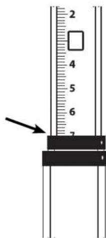
CONSTRUCTION GRADE ROD (FIG. 6)
DANGER:NEVER attempt to use a grade rod in a storm or near overhanging electric wires. Death or serious personal injury will occur.
The DEWALT Grade Rod is marked with measurement scales on both sides and is constructed in telescoping sections. A spring-loaded button actuates a lock to hold the grade rod at various lengths.
The front of the grade rod has the measurement scale starting at the bottom. Use this for measuring from the ground up when grading or leveling jobs. The back of the grade rod is designed to measure the height of ceilings, joists, etc. Fully extend the top section of the grade rod until the button locks into the previous section. Extend that section either until it locks into the adjacent section or until the grade rod touches the ceiling or joist. The height is read where the last extended section exits the previous lower section, as shown in Figure 6.
OPERATION
WARNING: Always observe the safety instructions and applicable regulations.
To extend battery life, remove batteries when the laser is not in use.
To ensure the accuracy of your work, check the laser calibration often. Refer to Field Calibration Check under Laser Maintenance.
- Before attempting to use the laser, make sure the tool is positioned on a relatively smooth, secure surface.
Always mark the center of the laser line or dot. If you mark different parts of the beam at different times you will introduce error into your measurements.
To increase working distance and accuracy, set up the laser in the middle of your working area.
- When attaching to a tripod or wall, mount the laser securely.
- When working indoors, a slow rotary head speed will produce a visibly brighter line; a faster rotary head speed will produce a visibly solid line.
To increase beam visibility, wear Laser Enhancement Glass es and/or use a Laser Target Card to help find the beam.
- Extreme temperature changes can cause movement or shifting of building structures, metal tripods, equipment, etc., which can effect accuracy. Check your accuracy often while working.
- When working with the DEWALT Digital Laser Detector, set the laser's rotation speed to the fastest setting.
- If the laser is dropped or suffers a sharp blow, have the calibration system checked by a qualified service centre before using the laser.
Laser Control Panel (fi g. 1)
The laser is controlled by the power button (e), the speed/rotation button (h), the scan mode button (j), and two arrows (j, k). The arrows control the movement of the laser head left and right when the laser is being used in the plumb mode.
TURNING THE LASER ON (FIG.1)
- Be sure that the batteries are properly installed and the battery door is securely closed.
CAUTION: The laser will operate even if battery door is not fully latched. To secure the batteries, always ensure battery door is closed and latched.
- Gently press the power button (e) to power the laser on. The power LED light (f) will illuminate and the unit will self-level.
NOTE: The LED indicator is used to indicate power-on (steady) and low battery (flashing).
NOTE: The head will begin or resume rotation once the laser is level.
TURNING THE LASER OFF
Gently press the power button to turn the laser off. The power LED indicator will no longer be illuminated.
Laser Control Panel Buttons (fi g. 1)
POWER BUTTON ①
Press the power button (e) to power the unit on and off.
ARROW BUTTONS
The arrow buttons (j, k) are used for different functions depending on the operating mode of the laser unit.
In Horizontal Mode:
The arrow buttons adjust the direction of the laser beam in Scan Mode or Pointing Mode (0 rpm).
In Vertical Mode:
The arrow buttons move the laser beam left and right.
ENGLISH
SPEED/ROTATION BUTTON
The speed/rotation button (h) is used to adjust the rotation speed of the laser beam through its 3 preset speeds.
The head speed will cycle through 3 speeds, then repeat the sequence as the speed/rotation button is pressed.
REMEMBER:
Slow Speed = Bright Beam Fast Speed = Solid Beam
NOTE: The speed/rotation button performs the same function as the speed/rotation button on the remote control.
SCAN MODE BUTTON
The scan mode button (i) is used to make the laser head sweep back and forth, creating a short, bright laser line. This short line is much brighter and more visible than when the unit is in full rotation mode.
Using Scan Mode:
To enter scan mode, push and release the scan mode button. To exit scan mode, push and release the button again.
The size and direction of the scan zone can be controlled with the arrow buttons on the laser unit control panel or the remote control. For a more detailed explanation, refer to Using the Wireless Remote Control.
The size and direction of the scan zone can also be controlled manually with the User Defined Scan Mode:
-
Set the laser unit at 0 rpm (pointer mode).
-
Manually rotate the laser head to po the laser beam at one edge of the desired scan zone.
-
Press and hold the scan button on the laser unit control panel. While holding down the scan button, manually rotate the laser head to the opposite edge of the desired scan zone.
-
Release the scan button.
- The laser will scan between the two selected points.
IMPORTANT: The remote control cannot be used for User Defined Scan Mode.
LOW BATTERY INDICATION
When the batteries approach end of life (g), the power LED (f) will begin to flash. When this signal is observed, only a short period of runtime is left before the unit will completely shut down. The batteries should be replaced with new batteries as soon as possible.
Using the Wireless Remote Control (fi g. 1)
The remote control allows one person to operate and setup the laser from a distance. The remote control features four arrows (m, n), speed/rotation button (o), scan mode button (p) and a manual mode button (j).
REMOTE CONTROL: ARROW BUTTONS

The arrow buttons (m, n) are used for different functions depending on the operating mode of the laser unit.
In Self-Leveling Horizontal Mode:
The up and down arrows (m) adjust the length of the laser line in Scan Mode.
The left and right arrows (n) adjust the direction of the laser beam in Scan Mode or Pointing Mode (0 rpm).
In Self-Leveling Vertical Mode:
The up and down arrows (m) adjust the position of the laser line in Scan Mode.
The left and right arrows (n) move the laser beam left and right.
REMOTE CONTROL: SPEED/ROTATION BUTTON
The speed/rotation button (o) is used to adjust the speed of the laser beam through its 3 preset speeds.
NOTE: The speed/rotation button performs the same function as the speed/rotation button on the control panel of the laser unit.
REMOTE CONTROL: SCAN MODE BUTTON

The scan mode button (p) is used to make the laser head sweep back and forth, creating a short, bright laser line. This short line is much brighter and more visible than when the unit is in full rotation mode.
Using Scan Mode:
To enter scan mode, push and release the scan mode button. To exit scan mode, push and release the button again.
The size and direction of the scan zone can be controlled with the arrow buttons on the laser unit control panel or the remote control. For a more detailed explanation, refer to Arrow Buttons under Laser Control Panel Buttons.
IMPORTANT: The remote control cannot be used for User Defined Scan Mode.
ENGLISH
Laser Accessories
LASER EN HANCEMENT GLASSES (FIG. 7)
These red lens glasses improve the visibility of the laser beam under bright light conditions or over long distances when the laser is used for interior applications. These glasses are not required to operate the laser.

DANGER: To reduce the risk of serious personal injury, never stare directly into the laser beam, with or without these glasses.

CAUTION: These glasses are not approved safety glasses and should not be worn while operating other tools. These glasses do not keep the laser beam from entering your eyes.
TARGET CARD (FIG. 8)
The Laser Target Card aids in locating and marking the laser beam. The target card enhances the visibility of the laser beam as the beam crosses over the card. The card is marked with standard and metric scales. The laser beam passes through the red plastic and reflects off of the reflective tape on the reverse side. The magnet at the top of the card is designed to hold the target card to ceiling track or steel studs to determine plumb and level positions. For best performance when using the Target Card, the DEWALT logo should be facing you.
DIGITAL LASER DETECTOR (FIG. 9)
The detector helps in locating the position of a laser beam in bright light conditions or over long distances. It produces both visual and audio signals as the rotating laser beam crosses the detector.
The detector can be used both indoors and outdoors whenever it is difficult to locate the laser beam.
The detector is not for use with non-rotating lasers but is compatible with most rotary red-beam or infrared (invisible) beam lasers on the market.
The DEWALT Digital Laser Detector can be used with or without the detector clamp. When used with the clamp, the detector can be positioned on a grade rod, leveling pole, stud or post.
Accuracy
When the laser is operated using the detector, the accuracy level of the detector needs to be added to that of the laser.
Nominal accuracy ± 3.0mm
Mounting Detector on a Grade Rod (fig. 9)
- To secure your detector to a grade rod, first attach the detector to the clamp by pushing in on the clamp latch (bb). Slide the tracks (cc) on
the clamp around the rail (dd) on the detector until the latch (ee) on the clamp pops into the latch hole (ff) on the detector.
- Open the jaws of the clamp by turning the clamp knob (gg) counterclockwise.
- Position the detector at the height needed and turn the clamp knob clockwise to secure the clamp on the rod.
- To make adjustments in height, slightly loosen the clamp, reposition and retighten.
Optional Accessories

WARNING: Since accessories, other than those offered by DeWALT, have not been tested with this product, use of such accessories with this laser could be hazardous. To reduce the risk of injury, only DeWALT-recommended accessories should be used with this product.
These are:
- DE0772 DEWALT Digital laser detector
DE0734 DEWALT Grade rod
DE0735 DEWALT Tripod
DE0736 DEWALT Tripod - DE0737 DEWALT Grade rod
- DE0738 DEWALT Gradient bracket
Consult your dealer for further information on the appropriate accessories.
MAINTENANCE
Your DEWALT laser unit has been designed to operate over a long period of time with a minimum of maintenance. Continuous satisfactory operation depends upon proper laser care and regular cleaning.
- To maintain the accuracy of your work, check the calibration of the laser often. Refer to Field Calibration Check.
- Calibration checks and other maintenance repairs can be performed by DEWALT service centres.
- When the laser is not in use, store it in the kit box provided.
- Do not store your laser in the kit box if the laser is wet. Dry exterior parts with a soft, dry cloth and allow the laser to air dry.
- Do not store your laser at temperatures below -18^ (0°F) or above 41^ (105°F).
ENGLISH
Field Calibration Check (fi g. 10-12)

WARNING: Always have the laser head calibrated by a qualified repair agent.
Field calibration checks should be done frequently.
NOTE: As part of the DEWALT guarantee, the owner is entitled to one FREE calibration service within the first year. Simply complete the enclosed voucher and return along with the laser and proof of purchase to an authorised DEWALT agent. A certificate will be awarded at no additional charge.
Field calibration checks do not calibrate the laser. These checks indicate whether or not the laser is providing a correct level and plumb line and do not correct errors in the leveling or plumbing capability of the laser.
These checks cannot take the place of professional calibration performed by a DeWALT service centre.
LEVEL CALIBRATION CHECK (X-AXIS)
- Set up a tripod between two walls that are at least 50 feet (15 m) apart. The exact location of the tripod is not critical.
- Mount the laser unit on the tripod so that the X-axis points directly toward one of the walls.
- Turn the laser unit on and allow it to self-level.
- Mark and measure points A and B on the walls as shown in Figure 10.
- Turn the entire laser unit 180^ so the X-axis points directly toward the opposite wall.
- Allow the laser unit to self-level, and mark and measure points AA and BB on the walls as shown in Figure 11.
- Calculate the total error using the equation:
Total Error = ( AA - A) - ( BB - B)
- Compare total error to the allowable limits shown in the following table.
| Distance between walls | Allowable Error |
| L = 15 m (50") 6 mm | (0.25") |
| L = 25 m (80") 10 mm | (0.4") |
| L = 50 m (160") 20 mm | (0.8") |
LEVEL CALIBRATION CHECK (Y-AXIS)
Repeat the procedure above, but with the laser unit positioned so the Y-axis is pointed directly toward the walls.
PLUMB ERROR CHECK (FIG. 12)
- Using a standard plumb bob as a reference, mark the top and bottom of a wall. (Be sure to mark the wall and not the floor and ceiling.)
- Position the rotary laser securely on the floor approximately 1m (3') from the wall.
- Turn the laser on, and point the dot at the mark on the bottom of the wall. Then, using the up/down arrows on the remote control, rotate the dot upwards. If the center of the dot scans over the mark on the top of the wall, the laser is properly calibrated.
NOTE: This check should be done with a wall no shorter than the tallest wall for which this laser will be used.

Cleaning

WARNING:
- Remove the batteries before cleaning your laser unit.
- Never use solvents or other harsh chemicals for cleaning the nonmetallic parts of the laser. Use a cloth dampened only with water and mild soap.
- Never let any liquid get inside the unit; never immerse any part of the unit into a liquid.
- Never use compressed air to clean the laser.
- Keep the ventilation slots clear and regularly clean the housing with a soft cloth.
The flexible rubber shield can be cleaned with a wet lint-free cloth such as a cotton cloth. USE WATER ONLY - DO NOT use cleansers or solvents. Allow the unit to air dry before storing.
Under some conditions, the glass lens inside the rotary head may collect some dirt or debris. This will affect beam quality and operating range. The lens should be cleaned with a cotton swab moistened with water.
Protecting the Environment

Separate collection. This product must not be disposed of with normal household waste.
Should you find one day that your DEWALT product needs replacement, or if it is of no further use to you, do not dispose of it with household waste. Make this product available for separate collection.

Separate collection of used products and packaging allows materials to be recycled and used again. Re-use of recycled materials helps prevent environmental pollution and reduces the demand for raw materials.
Local regulations may provide for separate collection of electrical products from the household, at municipal waste sites or by the retailer when you purchase a new product.
DEWALT provides a facility for the collection and recycling of DEWALT products once they have reached the end of their working life. To take advantage of this service please return your product to any authorised repair agent who will collect them on our behalf.
You can check the location of your nearest authorised repair agent by contacting your local DEWALT office at the address indicated in this manual. Alternatively, a list of authorised DEWALT repair agents and full details of our after-sales service and contacts are available on the Internet at: www.2helpU.com.
GUARANTEE
DEWALT is confident of the quality of its products and offers an outstanding guarantee for professional users of the product. This guarantee statement is in addition to and in no way prejudices your contractual rights as a professional user or your statutory rights as a private non-professional user. The guarantee is valid within the territories of the Member States of the European Union and the European Free Trade Area.
30 DAY NO RISK SATISFACTION GUARANTEE
If you are not completely satisfied with the performance of your DEWALT tool, simply return it within 30 days, complete with all original components, as purchased, to the point of purchase, for a full refund or exchange. The product must have been subject to fair wear and tear and proof of purchase must be produced.
- ONE YEAR FREE SERVICE CONTRACT
If you need maintenance or service for your DeWALT tool, in the 12 months following purchase, you are entitled to one service free of charge. It will be undertaken free of charge at an authorised DeWALT repair agent. Proof of purchase must be produced. Includes labour. Excludes accessories and spare parts unless failed under warranty.
- ONE YEAR FULL WARRANTY
If your DEWALT product becomes defective due to faulty materials or workmanship within 12 months from the date of purchase, DEWALT guarantees to replace all defective parts free of charge or - at our discretion - replace the unit free of charge provided that:
The product has not been misused;
The product has been subject to fair wear and tear;
- Repairs have not been attempted by unauthorised persons;
Proof of purchase is produced;
The product is returned complete with all original components.
If you wish to make a claim, contact your seller or check the location of your nearest authorised DEWALT repair agent in the DEWALT catalogue or contact your DEWALT office at the address indicated in this manual. A list of authorised DEWALT repair agents and full details of our after-sales service is available on the Internet at: www.2helpU.com.
ESPANOL
LASER ROTATIVO DW075
Enhorabuena!
ROTATION MANUELLE DE LA Tête (FIG. 1)
INSTALLATION AU SOL (FIG. 4, 5)
SCHEDA TARGET (FIG. 8)
AFSTANDSBEDIERING (AFB.1)
- Knop handmatige modus
WANDBEVESTIGING (AFB.2)
WANDBEVESTIGING (AFB.2)
KNOP SNELHEID/ROTATIE
DIGITALE LASERDETECTOR (AFB. 9)
(D-storrese)-batterier.
INSTALLERE BATTERIPAKKEN
SLA PÁ LASEREN (FIG. 1)
- Nominell nayaktiget ± 3,0 mm
Montere detektoren pa en gradestang (fig. 9)
-
For a feste detektoren til en gradestang fester du forst detektoren til klemmen ved a skyve den inn pa klemmens lasemekanisme (bb).For sporene (cc) pa klemmen rundt sporet (dd) pa detektoheten helt til lasemekanismen (ee) pa klemmen smelter inn i lasehullet (ff) pa detektoren.
-
Apne kjevene pa klemmen ved a vri klemmeknotten (gg) mot klokken.
-
Plasser detektoren i onsket hoyde og vri klemmeknotten med klokken for a sikre klemmen pa stangen.
- For à gîiore justeringer i hoyden losner du sá véd t à klemmen, posisjonerer den og strammer til à nytt.
Tilleggsutstyr

SE INTE INI STRÄLEN KCLASS 3R LASERPRODUKT
MANUELL ROTATION AV HUVUDET (FIG.1)
SKALSTAV FOR KONSTRUKTIONER (FIG. 6)
SLA PÁ LASERN (FIG. 1)
- ETT ARS FULLSTANDIG GARANTI
MANUEL KAFADONUSU (SEK.1)
Osnyies aopaaeia yia leizep

IPOEIOHOH!AiaBaoTe KAI kaVorOte oLc nC oNiyEc. H mI npoN OAW TWv OOnyiw Tou avaPepovTai napakatw EvExetai va OOnyaei OE NkTpoTTnEla, TnpKayia h/Kai oBapo npooWntiko TpaumiaJIo.
AIATHPSTE AYTEETOADHIE
MnV aeIoupyeIe To aeIeep Oe EKpnKTiKcEs aIIOOpaIeC, otw osrav uApxouv eUpEKA UyP, aiaP n Okov. Ta nAekpiKa epyaiaea oNMIoupyoV oNIVthpe TPO mOpov va Ippokaleou ov avapEeN OTnOkovn nTic avaBuaiaeIc.
Xpnoiopoieire to aeicep mov oE nC EIOIKA Oeioaoue cmuatape. H XpOJn pntapiwv aalou tounu npopei va Tpokaeaipukayia.
AtoBnkeoTe to lepou dev XpoJIOeIrae pocou dev npopoovva npoeyyioov raiaia Ka aaaa n EKtaieeuva atop. Ta lecp evai etikivova oTa xepia n EKtaieevvovxepiOTw.
Xpnoiopoioite Movo Eapntma tou auotuvta ano tv kataeuaotni yia to movrlo oac. Eapntma tou eivai katalna iya eva leicep, mtopei va 6niouoyov Kivduvo taupanoiou otav xpoioioioovtai oe aLo kiEep.
To epiou epyaieiou penta va ekiauiu ovo aopio npoawntikoeivw. H kteean ekeuw, oepic n ouvtipnoc an ovapoiogio npoosniokmuopevi odynoe i
paumio.ia va evtonie TE Tnnaeato eo gouaoofo nevo avinpopoawto oepic nC DEWALT,avapelte ot Niaota Tuv eouaootnevw avnpooow oepic nC DEWALT OTO mwo hpcos Tou npovtoc yxeiploou n EIOKEpTe IT OElaa www.2helpU.com 0to diaiktu.
Mynxpoaiomoiire ontka opyava, onwrcnlaekonia n biopcs, yia va deire ngdeaun aeep. Mtopei va npokanthetaapn baaonota maia.
Mv tototheite to aleep eTeToia 8e, Tou mtopei va npokalaeoi katoiov va koitalei, okotima n m, anf saeun aeip. Mtopei va npoklnei oBapn bAaBn Ota maia.
Mny toTOnotheTeItoLeicepKovTaOE avaklaotikn Emapaveia Toumuopei vaavakaoei thdosemuLeicep npocra paiaaAouatouu. Mtopei vaipokAnee oobapn bAaBn Oa pana.
OeTeTo AeiEep EKTOS AEioupyiaotav 6ev To xpoaioioe. Apivovtac to AeiEep OE AEioupyia auqavetai o kivuvoc va KOiTaeI KATIOc Tn Dcun AeiEep.
Mynxpnoiomtoie to aeep kovta o Tnaiia kai mny eniipentere o naiia va to xeiipotouv. Mnpoei va npokAnthei oBapn bAaBn Oa pna.
Mv aapaieTe kai mny kataotpeTe Tn poeiDtoointkEs tikTeEs. Eav apaepoov oi tkeTEs, o xpiotns n aaA atoua μtopevi ae kteoov akouia σe AKtivoBolia.
ToTOnoTeiToAeIepMaopalaia eE TIneBn Etnapaeia. Se nepinnwn nwn on Tou Aeiep, Evexetai va npokAntheta Baaon oTo Aeiep nOoapoc rpaunianos.
Na eioe vtuevoi katalnnla. Mny
opate papia evdujata n kounmuata.
MaieTre ta yapkiia paalia. Diatnpie ra
paalia, ta evdujata kai ta yavnia oac
pakia ano kivoumeva nepn. Ta papia
evdujata, ta kouniura n ta yapkiia paalia
muropovvaaykwoovcKivoumeva nepn.
Othupioe aepiaou ouxva kaluntiou
kivoumeva nepn kai tpeTt ETIanS va
aTOPEUYOTAI.
IPOEIOIHJH XpOg XepiOnpiW,oi Pooapouyec n EKTEeON Tuv diaikawu EPoTdoiaopetiko aot auov TOU pEPYpaeTAt OTo npov MTOpeVa oNynoeI eKthetaon 2 ENIIKIVDUnn AKTIVoBolia.
PPOEIIOIHSH! MHN
AINOESYNAPMOAOITE TO
NEPIPTPOIKO AIEZEP. Utapxouv oTo eovteipko Tumuata
Tou mtopei va emdiopwoei o
XeipiohC.H aTOOuvapmoAoynon
Tou npiotpoqikou aecep
0a kataohtaei akupecs
TcEyyuaneis Tou pIoovtoc
Mny tpoonoiie ro poiov
Kara otioiovnonre tpno. H
tpoTOnoiNtou epyaleiou mtopei
va odnyoei oe ekthetaon se Etnikivovn
AKTVoBOLia aeep.
IpoeiOoiinon yia to Aiecep.

AeEepKannyopia3R.

Katnyopia ppooTaiaq: IP54.
OEsH KQAIKOY HMEPOMHNIAZ
O Kwoikoc nepoyniac, o otioos Tepiaaabve ETTIOg TO EOC kataoekunS, EivaektutwEvos OTo KAtW Hepos Tou aeEep, KovTa OTo OTeipuata toTtoeTnns.
Napadéiyua:
2010 XX XX
EtoCATAOKEUN