
N1923B - Plane MAKITA - Free user manual and instructions
Find the device manual for free N1923B MAKITA in PDF.

User questions about N1923B MAKITA
0 question about this device. Answer the ones you know or ask your own.
Ask a new question about this device
Download the instructions for your Plane in PDF format for free! Find your manual N1923B - MAKITA and take your electronic device back in hand. On this page are published all the documents necessary for the use of your device. N1923B by MAKITA.
USER MANUAL N1923B MAKITA
Explanation of general view
① Bolt
② Drum
③ Planer blade
④ Drum cover
⑤ Adjust plate
⑥ Blade edge
⑦ Screws
⑧ Heel
9 Back side of gauge base
10 Inside edge of gauge plate
① Gauge plate
⑫ Gauge base
13 Pan head screw
14 Planer blade locating lugs
Heel of adjust plate
16 Set plate
⑦ Inside flank of gauge plate
18 Mini planer blade
19 Hex. flange head bolt
Groove
② Knob
2 Switch trigger
23 Lock button/ Lock-off button
24 Start
25 End
26 Blade edge
⑦ Cutting line
28 Screw
29 Edge fence
30 "V" groove
③1 Front base
③ Align the "V" groove with the edge of the workpiece.
33 Nozzle assembly
Chip cover screw
Chip cover
Fit pin on nozzle assembly into this hole.
37 Sharpening holder
38 Wing nut
39 Blade (A)
40 Blade (B)
41 Side (C)
42 Side (D)
Chip cover
44 Makita vacuum cleaner
45 Limit mark
46 Screwdriver
47 Brush holder cap
SPECIFICATIONS
Model 1923B/N1923B
Planing width 82 mm
Planing depth 1 mm
Shiplapping depth 23 mm
No load speed (RPM) 16,000
Overall length 293 mm
Net weight 2.9 kg
- Due to the continuing program of research and development, the specifications herein are subject to change without prior notice.
- Note: Specifications may differ from country to country.
Power supply
The machine should be connected only to a power supply of the same voltage as indicated on the 9 nameplate, and can only be operated on single-phase AC supply. They are double-insulated in accordance with European Standard and can, therefore, also be used from sockets without earth wire.
Safety hints
For your own safety, please refer to enclosed Safety2 instructions.
These symbols mean:

Read instruction manual.

DOUBLE INSULATION
ADDITIONAL SAFETY RULES
- Rags, cloth, cord, string and the like should never be left around the work area.
- Avoid cutting nails. Inspect for and remove all nails from the workpiece before operation.
- Handle the blades very carefully.
- Be sure the blade installation bolts are securely tightened before operation.
- Hold the machine firmly with both hands.
- Keep hands away from rotating parts.
- Before using the machine on an actual workpiece, let it run for a while. Watch for vibration or wobbling that could indicate poor installation or a poorly balanced blade.
- Make sure the blade is not contacting the workpiece before the switch is turned on.
9 Wait until the blade attains full speed before cutting. - Keep at least 200 mm away from the machine at all times.
- Always switch off and wait for the blades to come to a complete stop before any adjusting.
ty2. Never stick your finger into the chip chute.
Chute may jam when cutting damp wood.
Clean out chips with a stick. - Do not leave the machine running. Operate the machine only when hand-held.
- When leaving the planer, switch off and set it with the front base up on a wooden block, so that the blades do not contact anything.
- Always change both blades or covers on the drum, otherwise the resulting imbalance will cause vibration and shorten machine life.
- Wait for complete run-down before putting the machine aside.
- Use only Makita blades specified in this manual.
SAVE THESE INSTRUCTIONS.
OPERATING INSTRUCTIONS
Removing or installing planer blades
Important:
- Always be sure that machine is switched off and unplugged before removing or installing the blade.
- Use the following planer blades.
Part Nos. 793004-6 793007-0 793322-2
P-04226 P04282 P-04298
820044-1 820045-1 820043-1
Blades with * mark are available in European countries only. Consult your dealer or the Makita Service Center when purchasing blades. 5.
For machine with standard planer blades (Fig. 1, 3 & 4)
To remove the blades on the drum, unscrew the three installation bolts with the socket wrench. The drum cover comes off together with the blades.
To install the blades, first clean out all chips or foreign matter adhering to the drum or blades. Use blades of the same dimensions and weight, or drum oscillation/vibration will result, causing poor planing action and, eventually, machine breakdown.
Place the blade on the gauge base so that the blade edge is perfectly flush with the inside edge of the gauge plate. Place the adjust plate on the blade, then simply press in the heel of the adjust plate flush with
the back side of the gauge base and tighten two 9. screws on the adjust plate. Now slip the heel of the adjust plate into the drum groove, then fit the drum cover on it. Tighten the three installation bolts evenly and alternately with the socket wrench. The
For machine with mini planer blades (Fig. 1, 5 & 8)
- Remove the existing blade, if the machine has been in use, carefully clean the drum surfaces the drum cover. To remove the blades on the drum, unscrew the three installation bolts with socket wrench. The drum cover comes off together with the blades.
-
To install the blades, loosely attach the adjust plate to the set plate with the pan head screws and set the mini planer blade on the gauge base so that the cutting edge of the blade is perfectly flush with the inside flank of the gauge plate.
-
Set the adjust plate/set plate on the gauge base so that the planer blade locating lugs on the set plate rest in the mini planer blade groove, then press in the heel of the adjust plate flush with the back side of the gauge base and tighten the pan head screws.
- It is important that the blade sits flush with the inside flank of the gauge plate, the planer blade locating lugs sit in the blade groove and the heel of the adjust plate is flush with the back side of the gauge base. Check this alignment carefully to ensure uniform cutting.
- Slip the heel of the adjust plate into the groove of the drum.
- Set the drum cover over the adjust plate/set plate and screw in the three hex flange head bolts so that a gap exists between the drum and the set plate to slide the mini planer blade into position. The blade will be positioned by the planer blade
Reigrlocating lugs on the set plate.
of The blade's lengthwise adjustment will need to be manually positioned so that the blade ends are clear and equidistant from the housing on one side and the metal bracket on the other.
8 Tighten the three hex flange head bolts (with the blade socket wrench provided) and hand rotate the when drum to check clearances between the blade ends with and the machine body.
19. Check the three hex flange head bolts for finally tightness.
10. Repeat procedures 1 - 9 for other blade.
for shiplapping (Fig. 7).
The blade edge should be made to protrude outside slightly (0.3mm - 0.6mm) . Otherwise, nicks and generally poor shiplapping results.
ACQUATION:
Tighten the blade installation bolts carefully when attaching the blades to the machine. A loose installation bolt can be dangerous. Always check to see they are tightened securely.
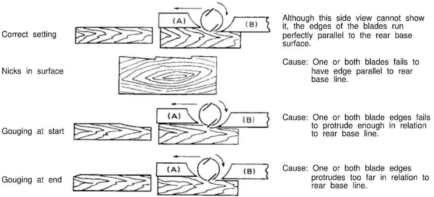
For the correct planer blade setting
Your planing surface will end up rough and uneven, unless the blade is set properly and securely. The blade must be mounted so that the cutting edge is absolutely level, that is, parallel to the surface of the rear base. Below are some examples of proper and improper settings.
(A) Front base (Movable shoe)
(B) Rear base (Stationary shoe)
Adjusting the depth of cut (Fig. 8)
Depth of cut may be adjusted by simply turning the knob on the front of the machine.
Switch action
CAUTION:
Before plugging in the machine, always check to see that the switch trigger actuates properly and returns the "OFF" position when released.
For machine without lock button and lock-off button (Fig. 9)
To start the machine, simply pull the trigger. Release the trigger to stop.
For machine with lock button (Fig. 10)
To start the machine, simply pull the trigger. Release the trigger to stop. For continuous operation, pull the trigger and then push in the lock button. To stop the machine from the locked position, pull the trigger fully, then release it.
For machine with lock-off button (Fig. 10)
To prevent the trigger from being accidentally pulled, a lock-off button is provided. To start the machine, press the lock-off button and pull the trigger. Release the trigger to stop.
Planing operation (Fig. 11)
First, rest the machine front base flat upon the workpiece surface without the blades making any contact. Switch on and wait until the blades attain full speed. Then move the machine gently forward. Apply pressure on the front of machine at the start of planing, and at the back at the end of planing. Planing will be easier if you incline the workpiece in stationary fashion, so that you can plane somewhat downhill. The speed and depth of cut determine the kind of finish. The power planer keeps cutting at a speed that will not result in jamming by chips. For rough cutting, the depth of cut can be increased, while for a good finish you should reduce the depth of cut and advance the machine more slowly.
Shiplapping (Fig. 12, 13, 14 & 15)
To make a stepped cut as shown in Fig. 12, use edge fence.
- Draw a cutting line on the workpiece. Insert the edge fence into the hole in the front of the machine. Also, the blade edge with the cutting line.
Adjust the edge fence until it comes in contact with side of the workpiece, then secure it by tightening screw.
You may wish to add to the length of the fence by attaching an extra piece of wood. Convenient holes are provided in the fence for this purpose, and also attaching an extension guide (optional accessory).
NOTE:
When planing, move the machine with the edge face flush with the side of the workpiece. Otherwise uneven planing may result.
Max. shiplapping depth is 23mm
Chamfering (Fig. 16, 17 & 18)
To make a cut as shown in Fig. 16, align the "V groove in the front base with the edge of the work piece and plane it as shown in the Fig. 18.
Nozzle assembly (optional accessory) (Fig. 19 & 20)
Use of the special nozzle assembly will minimize or scatter, making for a cleaner work area.
The nozzle assembly may be attached after the chip cover on the machine body is removed. When slipping on the assembly, fit the pin on it into the recover hole. Use the chip cover screws to fasten it place.
Sharpening the planer blades (Fig. 21, 22 & 23)
For standard blades only
Always keep your blades sharp for the best performance possible. Use the sharpening holder to remove nicks and produce a fine edge.
First, loosen the two wing nuts on the holder and insert the blades (A) and (B), so that they contact the sides (C) and (D). Then tighten the wing nuts.
Immerse the dressing stone in water for 2 or 3 minutes before sharpening. Hold the holder so that the blades both contact the dressing stone for simultaneous sharpening at the same angle.
Connecting a vacuum cleaner
the For European countries and areas (Fig. 24)
When you wish to perform clean planing operation, Ennect a Makita vacuum cleaner to your machine as shown in Fig. 24.
For other countries and areas
The nozzle and joint (optional accessories) are necessary to connect a Makita vacuum cleaner to your machine. Consult a Makita catalogue or representative on the nozzle and joint.
MAINTENANCE
CAUTION:
Always be sure that the machine is switched off and unplugged before carrying out any work on the machine.
Replacement of carbon brushes
(Fig. 25, 26 & 27)
Replace carbon brushes when they are worn down to the limit mark. First, remove the chip cover and then replace the carbon brushes. Both identical carbon brushes should be replaced at the same time.
To maintain product safety and reliability, repairs, maintenance or adjustment should be carried out by Makita Authorized Service Center.
GUARANTEE
We guarantee Makita machines in accordance with statutory/country-specific regulations. Damage attributable to normal wear and tear, overload or improper handling will be excluded from the guarantee. In case of complaint, please send the machine, undismantled, with the enclosed GUARANTEE CERTIFICATE, to your dealer or the Makita Service Center.
FRANÇAIS
Descriptif
Modello 1923B/N1923B
Max.schaafdiepe 1 mm
Sponningdiepe 23 mm
Toerental onbelast/min. 16000
m = 311 ;
fei
16
dr
( 2) S_ APQ = 12 · AQ · PQ = 12 × 2t × 4t = 42
1
D3
P
Ar
1
C
10 × 12
CC
C
…
as
m = 311 ;
m
。
V
05
63
- Repita os procedimentos indicados nos nu'meros 1 a 9 para colocar a outra la'mina.
Endast for standardknivar (HSS)
3-11-8, Sumiyoshi-cho,
Anjo, Aichi 446 Japan