
1806B - Plane MAKITA - Free user manual and instructions
Find the device manual for free 1806B MAKITA in PDF.


| Product type | Portable electric planer |
| Brand | Makita |
| Model | 1806B |
| Power supply | 230 V ~ 50 Hz |
| Rated power | 620 W |
| Planing width | 82 mm |
| Adjustable planing depth | 0 to 2 mm |
| Rebate depth (notch) | 0 to 25 mm |
| No-load speed | 16,000 rpm |
| Number of blades | 2 |
| Dimensions (L x W x H) | 290 x 165 x 160 mm |
| Weight | 3.5 kg |
| Parallel guide | Included |
| Protection class | Double insulation (class II) |
| Safety switch | With lock |
| Maintenance and cleaning | Clean after use, lubricate guides, replace blades if worn |
| Safety | Turn off and unplug before any adjustment or blade change |
| Spare parts | Replacement blades type Makita A-16706, A-16707 |
Frequently Asked Questions - 1806B MAKITA
User questions about 1806B MAKITA
0 question about this device. Answer the ones you know or ask your own.
Ask a new question about this device
Download the instructions for your Plane in PDF format for free! Find your manual 1806B - MAKITA and take your electronic device back in hand. On this page are published all the documents necessary for the use of your device. 1806B by MAKITA.
USER MANUAL 1806B MAKITA


1

2

3
4
5
6
7
8
9

10

11
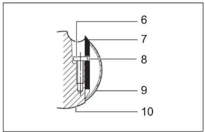
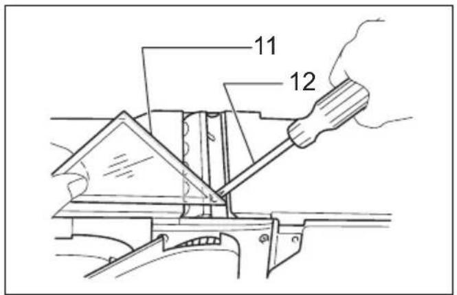
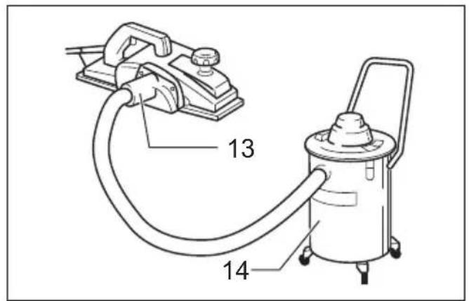
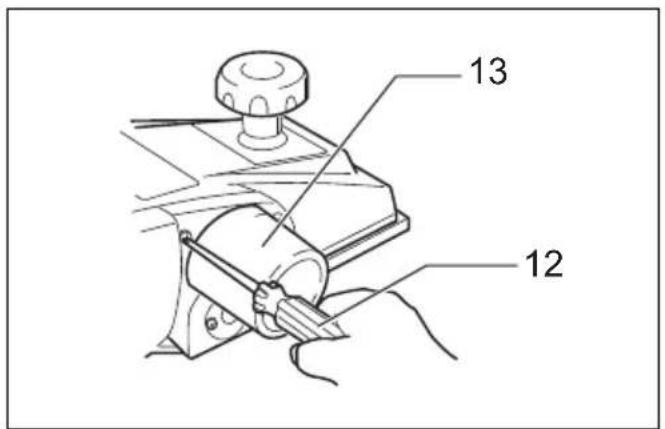
Explanation of general view
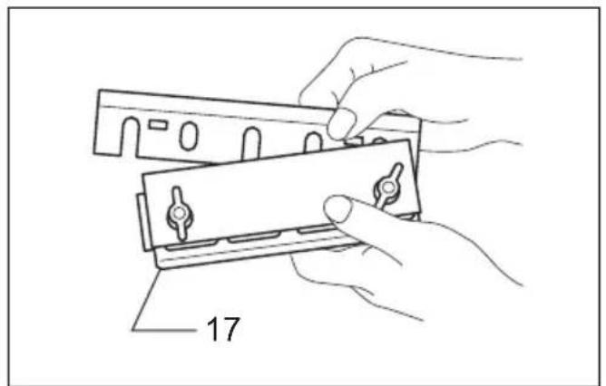
| 1 Knob | 9 Drum cover | 17 Sharpening holder |
| 2 Switch trigger | 10 Drum | 18 Wing nut |
| 3 Lock button/Lock-off button | 11 Triangular rule | 19 Blade (A) |
| 4 Hex wrench | 12 Screwdriver | 20 Blade (B) |
| 5 B o l t | 13 Nozzle | 21 Side (C) |
| 6 Adjusting screw | 14 Vacuum cleaner | 22 Side (D) |
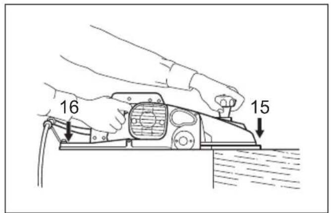
| 7 Planer blade | 15 Start | |
| 8 Notch in the blade | 16 End |
SPECIFICATIONS
GEB167-1
Model 1806B
Planing width 170 mm
Planing depth 2 mm
No load speed (min -1 ) 15,000
Overall length 529 mm
Net weight 8.8 kg
Safety class ....[1]
- Due to our continuing program of research and development, the specifications herein are subject to change without notice.
- Specifications may differ from country to country.
- The net weight value includes the attachment(s) for normal and safe use which are specified in the instruction manual.
ENE001-1
Intended use
The tool is intended for planing wood.
ENF002-2
Power supply
The tool should be connected only to a power supply of the same voltage as indicated on the nameplate, and can only be operated on single-phase AC supply. They are double-insulated and can, therefore, also be used from sockets without earth wire.
ENF100-1
For public low-voltage distribution systems of between 220 V and 250 V
Switching operations of electric apparatus cause voltage fluctuations. The operation of this device under unfavorable mains conditions can have adverse effects to the operation of other equipment. With a mains impedance equal or less than 0.41 Ohms it can be presumed that there will be no negative effects.
The mains socket used for this device must be protected with a fuse or protective circuit breaker having slow tripping characteristics.
GEA010-2
General power tool safety warnings
⚠ WARNING Read all safety warnings, instructions, illustrations and specifications provided with this power tool. Failure to follow all instructions listed below may result in electric shock, fire and/or serious injury.
Save all warnings and instructions for future reference.
The term “power tool” in the warnings refers to your mains-operated (corded) power tool or battery-operated (cordless) power tool.
PLANER SAFETY WARNINGS
- Wait for the cutter to stop before setting the tool down. An exposed rotating cutter may engage the surface leading to possible loss of control and serious injury.
- Hold the power tool by insulated gripping surfaces, because the cutter may contact its own cord. Cutting a "live" wire may make exposed metal parts of the power tool "live" and could give the operator an electric shock.
- Use clamps or another practical way to secure and support the workpiece to a stable platform. Holding the workpiece by your hand or against the body leaves it unstable and may lead to loss of control.
- Rags, cloth, cord, string and the like should never be left around the work area.
- Avoid cutting nails. Inspect for and remove all nails from the workpiece before operation.
- Use only sharp blades. Handle the blades very carefully.
- Be sure the blade installation bolts are securely tightened before operation.
- Hold the tool firmly with both hands.
- Keep hands away from rotating parts.
- Before using the tool on an actual workpiece, let it run for a while. Watch for vibration or wobbling that could indicate poor installation or a poorly balanced blade.
- Make sure the blade is not contacting the workpiece before the switch is turned on.
- Wait until the blade attains full speed before cutting.
- Always switch off and wait for the blades to come to a complete stop before any adjusting.
- Never stick your finger into the chip chute. Chute may jam when cutting damp wood. Clean out chips with a stick.
- Do not leave the tool running. Operate the tool only when hand-held.
- Always change both blades or covers on the drum, otherwise the resulting imbalance will cause vibration and shorten tool life.
- Use only Makita blades specified in this manual.
- Always use the correct dust mask/respirator for the material and application you are working with.
SAVE THESE INSTRUCTIONS.
WARNING:
DO NOT let comfort or famili (gained from repeated use) replace strict adherence to safety rules for the subject product.
MISUSE or failure to follow the safety rules stated in this instruction manual may cause serious personal injury.
FUNCTIONAL DESCRIPTION
CAUTION:
- Always be sure that the tool is switched off and unplugged before adjusting or checking function on the tool.
Adjusting the depth of cut (Fig. 1)
Depth of cut may be adjusted by simply turning the knob on the front of the tool.
Switch action (Fig. 2)
CAUTION:
- Before plugging in the tool, always check to see that the switch trigger actuates properly and returns to the "OFF" position when released.
For tool with lock button
To start the tool, simply pull the switch trigger. Release the switch trigger to stop.
For continuous operation, pull the switch trigger and then push in the lock button.
To stop the tool from the locked position, pull the switch trigger fully, then release it.
For tool with lock-off button
To prevent the switch trigger from being accidentally pulled, a lock-off button is provided.
To start the tool, depress the lock-off button and pull the switch trigger. Release the switch trigger to stop.
ASSEMBLY
CAUTION:
- Always be sure that the tool is switched off and unplugged before carrying out any work on the tool.
Removing or installing planer blades (Fig. 3, 4 & 5)
CAUTION:
- Tighten the blade installation bolts carefully when attaching the blades to the tool. A loose installation bolt can be dangerous. Always check to see they are tightened securely.
- Handle the blades very carefully. Use gloves or rags to protect your fingers or hands when removing or installing the blades.
- Use only the Makita wrench provided to remove or install the blades. Failure to do so may result in over-tightening or insufficient tightening of the installation bolts. This could cause an injury.
To remove the blades on the drum, unscrew the five installation bolts with the den wrench. The drum cover comes off together with the blades.
To install the blades, first clean out all chips or foreign matter adhering to the drum or blades. Use blades of the same dimensions and weight, or drum oscillation /vibration will result, causing poor planing action and eventually tool breakdown.
There are two adjusting screws for each blade. When installing the blade, the notch in the blade should fit over the head of the adjusting screw. Then fit on the drum cover and secure the five bolts only finger-tight.
Turn the drum until the blade edge is right in the middle between the front and rear bases.
Place the triangular rule flat on the rear base and run it out over and across the blade edge. Turn the two adjusting screws to adjust the blade protrusion. The blade setting should be made so that the protrusion will be uniform all the way across. Thus the triangular rule should be flush with the entire width of the blade edge. After adjusting both blades, tighten all the installation bolts evenly and alternately with the hex wrench.
After tightening the bolts, secure the adjusting screws fully.
For the correct planer blade setting
Your planing surface will end up rough and uneven, unless the blade is set properly and securely. The blade must be mounted so that the cutting edge is absolutely level, that is, parallel to the surface of the rear base.
Refer to some examples below for proper and improper settings.
(A) Front base (Movable shoe)
(B) Rear base (Stationary shoe)

Dust
WARNING:
- Depending on the material being worked on and the accessory used, the dust created by use of the tool can be harmful. The user is recommended to use an appropriate dust extractor to reduce exposure.
See the "OPTIONAL ACCESSORIES" section in this instruction manual for all optional dust extractor attachments available.
Additional Warnings:
• To prevent dust inhalation, it is recommended to also wear an FFP2 dust mask or P2 respirator.
- Read the "MAINTENANCE" section of the instruction manual of the connected dust extractor to keep the dust collection effective.
- Follow all applicable regulatory requirements for dust control in the country where the work is being conducted.
- Do not use a dust extractor for metalworking with power tools. Metal particles produced during metalworking can ignite accumulated dust and damage the dust filter inside dust extractors, posing a serious fire hazard.
- For European countries only
The user is recommended to use an M or H dust class extractor (as defined in EN 60335-2-69).
For help and support regarding dust extractors, please contact your local Makita Service Center.
Connecting with a dust extractor (Fig. 6)
NOTE:
- In some countries, the nozzle may not be included in the tool package as standard accessory.
For tool with nozzle
Connect a hose of the vacuum cleaner to the nozzle.
Use the front cuff 38 to connect the hose.
The inner diameter of the nozzle for the hose connection is 45 mm.
For tool without nozzle (Fig. 7)
- Remove the chip cover from the tool.
- Install the nozzle on the tool using the screws.
- Connect a hose of the vacuum cleaner to the nozzle.
Use the front cuff 38 to connect the hose.
The inner diameter of the nozzle for the hose connection is 45 mm.
Nozzle cleaning
Clean the nozzle regularly.
Use a compressed air to clean the clogged nozzle.
OPERATION
WARNING:
- To reduce the risk of injury to persons, do not operate without nozzle or chip cover in place.
Planing operation (Fig. 8)
First, rest the tool front base flat upon the workpiece surface without the blades making any contact. Switch on and wait until the blades attain full speed. Then move the tool gently forward. Apply pressure on the front of tool at the start of planing, and at the back at the end of planing. Planing will be easier if you incline the workpiece in stationary fashion, so that you can plane somewhat downhill.
The speed and depth of cut determine the kind of finish. The power planer keeps cutting at a speed that will not result in jamming by chips. For rough cutting, the depth of cut can be increased, while for a good finish you should reduce the depth of cut and advance the tool more slowly.
MAINTENANCE
CAUTION:
- Always be sure that the tool is switched off and unplugged before attempting to perform inspection or maintenance.
- Never use gasoline, benzine, thinner, alcohol or the like. Discoloration, deformation or cracks may result.
To maintain product SAFETY and RELIABILITY, repairs, carbon brush inspection and replacement, any other maintenance or adjustment should be performed by Makita Authorized or Factory Service Centers, always using Makita replacement parts.
Sharpening the planer blades (Fig. 9, 10 & 11)
Always keep your blades sharp for the best performance possible. Use the sharpening holder to remove nicks and produce a fine edge.
First, loosen the two wing nuts on the holder and insert the blades (A) and (B), so that they contact the sides (C) and (D). Then tighten the wing nuts.
Immerse the dressing stone in water for 2 or 3 minutes before sharpening. Hold the holder so that the both blades contact the dressing stone for simultaneous sharpening at the same angle.
OPTIONAL ACCESSORIES
CAUTION:
• These accessories or attachments are recommended for use with your Makita tool specified in this manual. The use of any other accessories or attachments might present a risk of injury to persons. Only use accessory or attachment for its stated purpose.
If you need any assistance for more details regarding these accessories, ask your local Makita service center.
• High-speed steel Planer blade
- Sharpening holder assembly
- Blade gauge
- Edge fence (Guide rule)
- Extension guide set
- Dressing stone
- Nozzle assembly
- Hex wrench
NOTE:
- Some items in the list may be included in the tool package as standard accessories. They may differ from country to country.
ENG905-1
Noise
The typical A-weighted noise level determined according to EN62841-2-14:
Sound pressure level ( LpA ): 91 dB (A)
Sound power level ( LWA ): 99 dB (A)
Uncertainty (K): 3 dB (A)
NOTE:
- The declared noise emission value(s) has been measured in accordance with a standard test method and may be used for comparing one tool with another.
- The declared noise emission value(s) can also be used in a preliminary assessment of exposure.
WARNING:
- Wear ear protection.
- The noise emission during actual use of the power tool can differ from the declared total value(s) depending on the ways in which the tool is used.
- Be sure to identify safety measures to protect the operator that are based on an estimation of exposure in the actual conditions of use (taking account of all parts of the operating cycle such as the times when the tool is switched off and when it is running idle in addition to the trigger time).
Vibration
The continuous vibration total value (tri-axial vector sum) determined according to EN62841-2-14:
Work mode: planing softwood
Vibration emission ( ah ): 2.5 m/s 2
Uncertainty (K): 1.5 m/s 2
NOTE:
- The declared vibration total value(s) has been measured in accordance with a standard test method and may be used for comparing one tool with another.
- The declared vibration total value(s) can also be used in a preliminary assessment of exposure.
WARNING:
- The vibration emission during actual use of the power tool can differ from the declared total value(s) depending on the ways in which the tool is used.
- Be sure to identify safety measures to protect the operator that are based on an estimation of exposure in the actual conditions of use (taking account of all parts of the operating cycle such as the times when the tool is switched off and when it is running idle in addition to the trigger time).
The following shows the mean values of the peak amplitude of the acceleration from repeated shock vibrations, pF , with corresponding uncertainty (K) determined according to EN62841-2-14.
Work mode: planing softwood
pF : 249 m/s²
Uncertainty (K): 47 m/s 2
NOTE:
• These declared values should not be used to determine hand arm vibration exposure.
DECLARATIONS OF CONFORMITY
For European countries only
The EU Declaration of Conformity can be accessed from the following URL.

https://support.makita.biz/doc/doc_index.html
For the UK
Annex A to this instruction manual or in digital format using the above URL.
Descriptif
DÉCLARATIONS DE CONFORMITÉ
OPTIONELE ACCESSOIRES
LET OP:


- SPECIFICATIONS
- MODEL 1806B
- INTENDED USE
- POWER SUPPLY
- FOR PUBLIC LOW-VOLTAGE DISTRIBUTION SYSTEMS OF BETWEEN 220 V AND 250 V
- GENERAL POWER TOOL SAFETY WARNINGS
- SAVE ALL WARNINGS AND INSTRUCTIONS FOR FUTURE REFERENCE
- PLANER SAFETY WARNINGS
- SAVE THESE INSTRUCTIONS
- WARNING
- FUNCTIONAL DESCRIPTION
- CAUTION
- ADJUSTING THE DEPTH OF CUT (FIG. 1)
- SWITCH ACTION (FIG. 2)
- FOR TOOL WITH LOCK BUTTON
- FOR TOOL WITH LOCK-OFF BUTTON
- ASSEMBLY
- REMOVING OR INSTALLING PLANER BLADES (FIG. 3, 4 & 5)
- FOR THE CORRECT PLANER BLADE SETTING
- DUST
- ADDITIONAL WARNINGS
- CONNECTING WITH A DUST EXTRACTOR (FIG. 6)
- NOTE
- FOR TOOL WITH NOZZLE
- FOR TOOL WITHOUT NOZZLE (FIG. 7)
- NOZZLE CLEANING
- OPERATION
- PLANING OPERATION (FIG. 8)
- MAINTENANCE
- SHARPENING THE PLANER BLADES (FIG. 9, 10 & 11)
- OPTIONAL ACCESSORIES
- NOISE
- VIBRATION
- DECLARATIONS OF CONFORMITY
- FOR EUROPEAN COUNTRIES ONLY
- FOR THE UK
- DÉCLARATIONS DE CONFORMITÉ
- OPTIONELE ACCESSOIRES
- LET OP
Brand : MAKITA
Model : 1806B
Category : Plane