UniversalAngle - Measuring equipment BOSCH - Free user manual and instructions
Find the device manual for free UniversalAngle BOSCH in PDF.

| Product type | Angle measurer |
| Brand | Bosch |
| Model | UniversalAngle |
| Category | Measuring equipment |
| Measuring range | 0° to 220° |
| Measurement accuracy (angle) | ±0.2° |
| Measurement accuracy (vial) | 1.5 mm/m |
| Accuracy of angle calculation | ±0.1° |
| Operating temperature | -10 °C to +50 °C |
| Storage temperature | -20 °C to +70 °C |
| Max. operating altitude | 2000 m |
| Power supply | 2 x 1.5 V LR6 (AA) batteries |
| Battery life | Approx. 25 h |
| Auto-off | After approx. 5 min |
| Leg length | 400 mm |
| Weight (according to EPTA) | 0.89 kg |
| Dimensions (L × W × H) | 425 × 41 × 58 mm |
| Display | Backlit |
| Spirit levels | Horizontal and vertical |
| Main functions | Angle measurement and transfer, calculation of single and double miter angles, squareness check |
| Included accessories | Leg extension |
| Maintenance | Clean with a soft, damp cloth; do not use solvents |
| Safety | Do not use in explosive atmospheres; repair by qualified personnel only |
Frequently Asked Questions - UniversalAngle BOSCH
User questions about UniversalAngle BOSCH
0 question about this device. Answer the ones you know or ask your own.
Ask a new question about this device
Download the instructions for your Measuring equipment in PDF format for free! Find your manual UniversalAngle - BOSCH and take your electronic device back in hand. On this page are published all the documents necessary for the use of your device. UniversalAngle by BOSCH.
USER MANUAL UniversalAngle BOSCH
natural_image
3D technical illustration of a mechanical device with no visible text or symbolsEnglish ...... Page 22
natural_image
Interior view of a room with windows, a bench, and a window with a wooden scale (no text or symbols)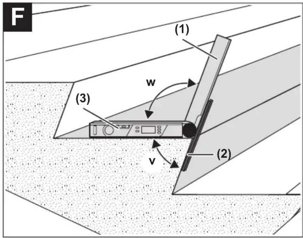
Bosch Power Tools 1 609 92A 85L | (14.11.2022)
8
Deutsch
Sicherheitshinweise

natural_image
Diagram showing a 3D object interacting with a wall, with an angle labeled X° and a power outlet symbol nearby (no text or symbols beyond basic geometry)www.bosch-pt.com/serviceaddresses
Entsorgung
All instructions must be read and observed. The safeguards integrated into the measuring tool may be compromised if the measuring tool is not used in accordance with these instructions. STORE THESE INSTRUCTIONS IN A SAFE PLACE.
▶ Have the measuring tool serviced only by a qualified specialist using only original replacement parts. This will ensure that the safety of the measuring tool is maintained.
▶ Do not use the measuring tool in explosive atmospheres which contain flammable liquids, gases or dust. Sparks may be produced inside the measuring tool, which can ignite dust or fumes.
When sawing workpieces for which you have determined the angle using this measuring tool, always strictly follow the safety instructions and working advice for the saws in use (including instructions on positioning and clamping the workpiece). When the required angles cannot be set on a certain saw or saw type, alternative sawing methods will need to be applied. Extremely acute (sharp) angles can be cut using a taper jig with a table saw or a circular saw.
Product Description and Specifications
Please observe the illustrations at the beginning of this operating manual.
Intended Use
The measuring tool is intended for measuring and transferring angles, calculating simple and compound mitre/bevel angles, and checking and aligning mitre and bevel angles.
The measuring tool is suitable for indoor use.
Product Features
The numbering of the product features shown refers to the illustration of the measuring tool on the graphic page.
(1) Fold-out leg
(2) Leg extension
(3) Base leg
(4) Illuminated display
(5) Level for horizontal alignment
(6) Level for vertical alignment
(7) Button for compound mitre COM
(8) Button for simple mitre MTR
(9) Hold/Clear button Hold
(10) Button for supplementary angle 180^
(11) On/off button
(12) Battery compartment
(13) Serial number
(14) Locking mechanism of the battery compartment cover
(15) Battery compartment cover
(16) Scale on leg extension
Display elements
(a) Measured value
(b) Battery charge indicator/battery warning
(c) Supplementary angle indicator SUP
(d) Spring angle indicator SPR
(e) Corner angle indicator CNR
24 | English
(f) Horizontal mitre angle indicator MTR
(g) Bevel angle indicator BVL
(h) Saved value indicator HOLD
Technical Data
| Digital angle measuring device UniversalAngle | |
| Article number | 3 603 F76 0.. |
| Measuring range 0°-220° | |
| Measuring accuracy | |
| - Angle ±0.2° | |
| - Spirit level 1.5 mm/m | |
| Calculated angle accuracy ±0.1° | |
| Operating temperature -10 °C to +50 °C | |
| Storage temperature -20 °C to +70 °C | |
| Max. altitude 2000 m | |
| Relative air humidity max. 90 % | |
| Pollution degree according to IEC 61010-1 2 | A) |
| Batteries 2 × 1.5 V LR6 (AA) | |
| Operating time, approx. 25 h | |
| Automatic switch-off after approx. 5 min | |
| Leg length 400 mm | |
| Weight according to EPTA-Procedure 01:2014 | 0.89 kg |
| Dimensions 425 × 41 × 58 mm | |
A) Only non-conductive deposits occur, whereby occasional temporary conductivity caused by condensation is expected.
The serial number (13) on the type plate is used to clearly identify your measuring tool.
Assembly
Inserting/replacing batteries (see figure A)
It is recommended that you use alkaline manganese batteries to operate the measuring tool.
Press the locking mechanism (14) to open the battery compartment cover (15) and remove the battery compartment cover. Insert the non-rechargeable batteries. When inserting the batteries, ensure that the polarity is correct according to the illustration on the inside of the battery compartment.
When the battery low indicator (b) is shown in the display for the first time during operation, measurements can be made for only about 1–2 hours.
When the battery low indicator (b) flashes, the batteries or rechargeable batteries must be replaced. It is no longer possible to carry out measurements.
Always replace all the batteries at the same time. Only use batteries from the same manufacturer and which have the same capacity.
▶ Take the batteries out of the measuring tool when you are not using it for a prolonged period of time. The batteries can corrode and self-discharge during prolonged storage in the measuring tool.
Attaching the Leg Extension (see figure B)
Slide the leg extension (2) from the front onto the fold-out leg (1). Push the leg extension as far as required over the joint of the measuring tool.
Operation
Starting Operation
▶ Protect the measuring tool from moisture and direct sunlight.
Do not expose the measuring tool to any extreme temperatures or variations in temperature. For example, do not leave it in a car for extended periods of time. In case of large variations in temperature, allow the measuring tool to adjust to the ambient temperature before putting it into operation. The precision of the measuring tool may be compromised if exposed to extreme temperatures or variations in temperature.
▶ Keep the supporting surfaces and contact edges of the measuring tool clean. Protect the measuring tool against shock and impact. Dirt particles or deformations can lead to faulty measurements.
Switching On and Off
To switch on the measuring tool, press the on/off button (11).
26 | English
After switching on, the measuring tool is in "normal measuring" operating mode.
To switch off the measuring tool, press the on/off button (11).
When no activity is performed on the measuring tool for approx. 5 minutes, the measuring tool automatically switches off to save the batteries.
Aligning with the Spirit Levels
The measuring tool can be aligned horizontally with spirit level (5) and vertically with spirit level (6).
The measuring tool can also be used as a carpenter's spirit level for checking vertical and horizontal lines. For this, place or hold the measuring tool against the surface subject to checking.
"Normal measuring" Operating Mode
After switching on, the measuring tool is always in "normal measuring" operating mode.
Measuring Angles (see figures C-E)
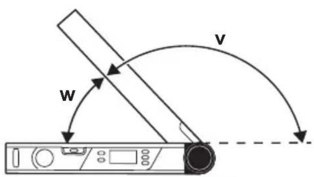
Place the fold-out leg (1) and the base leg (3) flat on the surfaces adjacent to the angle. The displayed measured value (a) corresponds with the interior angle w between the base leg and the fold-out leg.
This measured value is shown on the display (4) until you change the angle between fold-out leg (1) and base leg (3).
Transferring Angles (see figure C)
Measure the angle to be transferred by placing the fold-out leg and base leg on the target angle.
Place the measuring tool in the required position against the workpiece. Use the legs as a straight edge to transfer the angle.
Ensure that the fold-out and base legs are not moved during transfer.
Marking Angles (see figure D)
Open the fold-out leg and the base leg until the required angle is indicated in the measured value display (a).
Place the measuring tool in the required position against the workpiece. Use the legs as a straight edge to transfer the angle.
Storing the Measured Value
Press the Hold (9) button to store (HOLD) the current measured value (a).
The measured value is displayed, regardless of whether the base leg and fold-out leg are moved, until you press the Hold (9) button again.
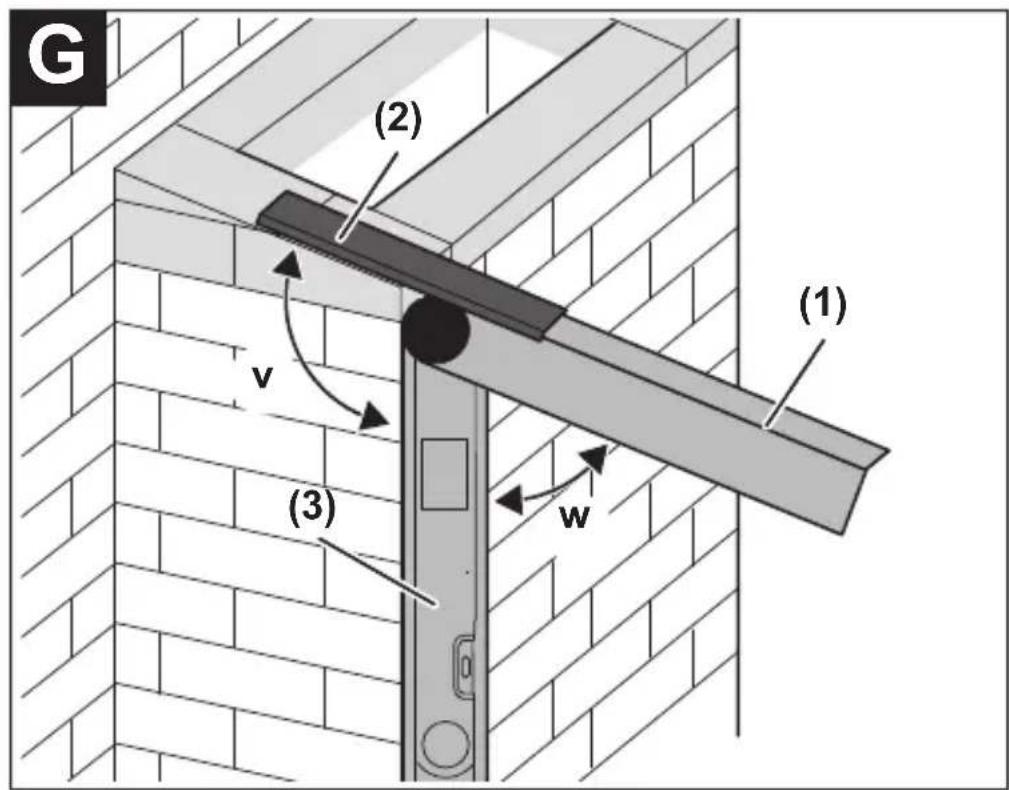
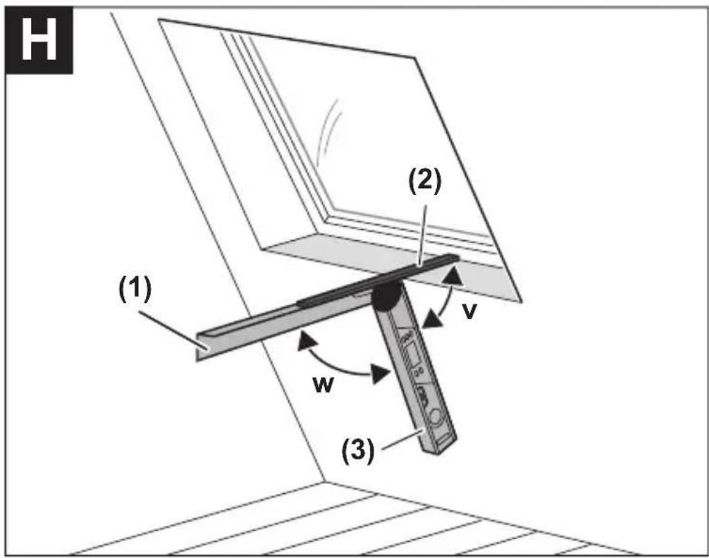
Measuring with Leg Extension (see figures F-H)
The leg extension (2) makes it possible to measure angles when the contact surface is shorter than the fold-out leg (1).
Attach the leg extension (2) (see "Attaching the Leg Extension (see figure B)", page 25). Place the base leg (3) and the leg extension (2) flat on the surfaces adjacent to the angle.
The measured value of the angle w between base leg and fold-out leg is indicated in the display. The required angle v between base leg and leg extension is calculated as follows:
$$ \mathbf {v} = 1 8 0 ^ {\circ} - \mathbf {w} $$
If you press the 180^ (10) button, the required angle v (supplementary angle) will be calculated and displayed.
"Simple Mitre" Measurement
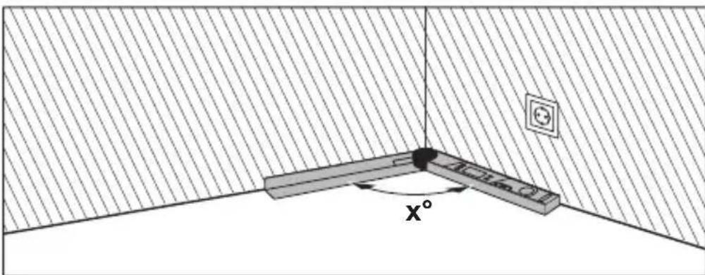
The "Simple mitre" measurement is used to calculate the cutting angle MTR when two workpieces with the same mitre have to form any outer angle x^ smaller than 180^ (e.g. for skirting boards, banister columns or picture frames).
28 | English
natural_image
Diagram showing a 3D object interacting with a wall, with an angle labeled X° and a power outlet symbol (no text or labels beyond basic geometry)When workpieces are to be fitted into a corner (e.g. for skirting boards), measure the corner angle x^ by positioning the fold-out leg and the base leg. For given angles (e.g. picture frames), open the fold-out leg and the base leg until the required angle is indicated in the display.
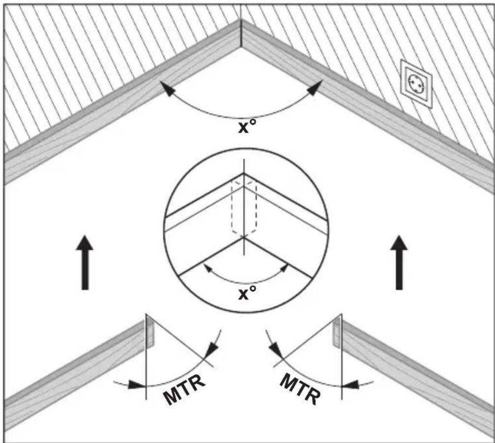
The mitre angle MTR, by which the two workpieces are to be shortened, is calculated. For these mitre/bevel cuts, the saw blade is perpendicular to the workpiece (the bevel angle is 0^ ).
Press the MTR (8) button. As long as you hold down the MTR (8) button, the calculated mitre angle MTR, which has to be set on the mitre saw, will be displayed. At the same time, the MTR indicator will light up in the display.
Note: The calculated mitre angle MTR can only be transferred for mitre saws, for which the setting for vertical cuts is 0^ . When the setting for vertical cuts is 90^ , the angle for the saw must be calculated as follows: 90^ – displayed angle MTR = angle to be set for the saw.
"Compound Mitre" Measurement
The "Compound mitre" ("Compound MTR") measurement is used to calculate mitre and bevel angles when two workpieces with multiple angles (e.g. crown mouldings) have to join precisely.
First measure the spring angle SPR and the corner angle CNR. The measuring tool will then calculate the mitre angle MTR and the bevel angle BVL.
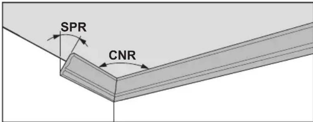
Carry out the worksteps exactly in the given sequence.
30 | English
1. SPR: Storing the spring angle
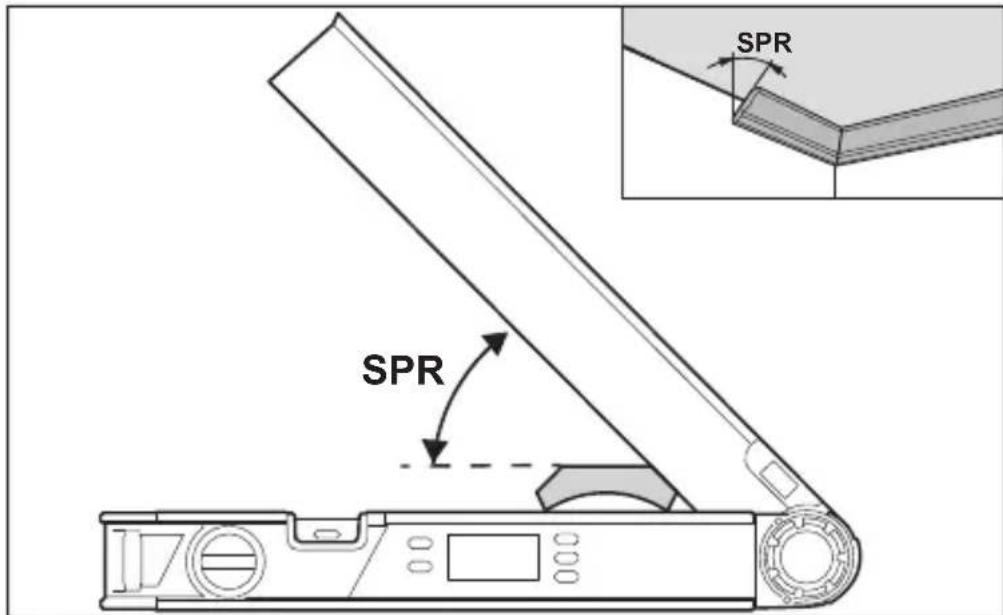
The spring angle can be saved as follows:
- Open the fold-out leg and base leg until the required spring angle is shown on the display.
- Measure the spring angle if it is unknown. For this, place the workpiece to be measured between the fold-out leg and the base leg.
When measuring particularly narrow or small workpieces with the measuring tool is not possible, use auxiliary equipment such as a bevel angle or mitre rule, and then adjust the angle on the measuring tool.
Press the COM (7) button to store the measured spring angle for the compound mitre. SPR and the current angle will appear on the display.
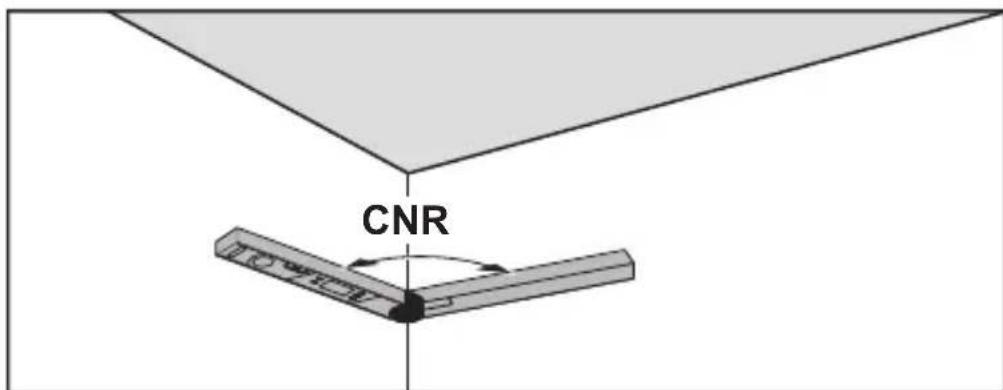
2. CNR: Storing the corner angle
1 609 92A 85L | (14.11.2022) Bosch Power Tools
To measure the corner angle, place the fold-out and base legs flat against the walls or set a known corner angle on the measuring tool.
Press the COM (7) button again to store the measured corner angle for the compound mitre. CNR and the current angle will appear on the display.
3. MTR: Calculating the mitre angle
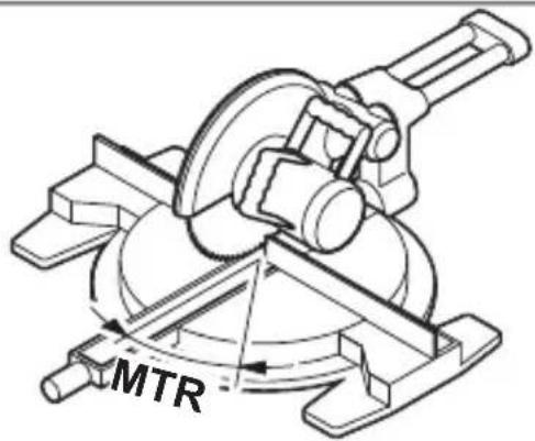
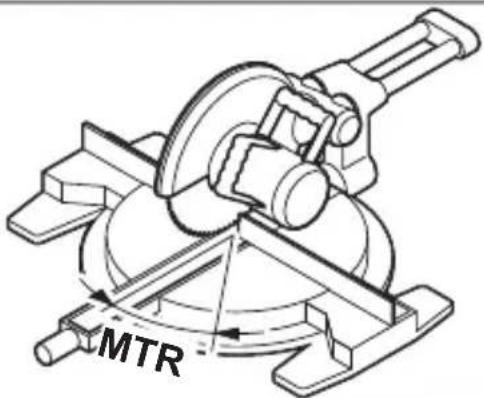
Press the COM (7) button again. MTR and the calculated mitre angle for the mitre saw are indicated on the display. The mitre angle is used to define the rotation of the saw table (MTR).
4. BVL: Calculating the bevel angle
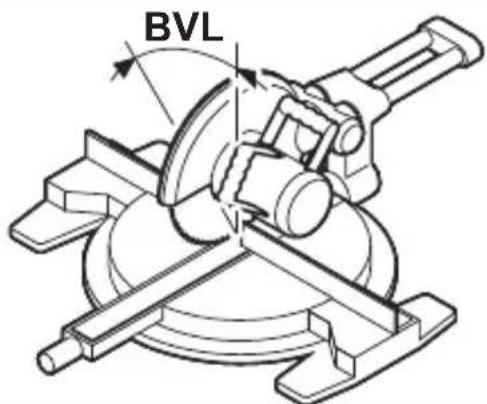
Press the COM (7) button again. BVL and the calculated bevel angle for the mitre saw are indicated on the display.
The bevel angle is used to define the incline of the saw blade (BVL).
Notes on "Compound Mitre" Operating Mode
The calculated mitre angle MTR can only be transferred for mitre saws, for which the setting for vertical cuts is 0^ . When the setting for vertical cuts is
32 | English
90^ , the angle for the saw must be calculated as follows: 90^ – displayed angle MTR = angle to be set for the saw.
Maintenance and Service
Maintenance and Cleaning
Keep the measuring tool clean at all times.
Never immerse the measuring tool in water or other liquids.
Wipe off any dirt using a damp, soft cloth. Do not use any detergents or solvents.
When the measuring tool is exposed to rain for an extended period, its function may be impaired. However, after completely drying off, the measuring tool is ready for operation. No calibration is required.
After-Sales Service and Application Service
Our after-sales service responds to your questions concerning maintenance and repair of your product as well as spare parts. You can find explosion drawings and information on spare parts at: www.bosch-pt.com
The Bosch product use advice team will be happy to help you with any questions about our products and their accessories.
In all correspondence and spare parts orders, please always include the 10-digit article number given on the nameplate of the product.
Great Britain
Robert Bosch Ltd. (B.S.C.)
P.O. Box 98
Broadwater Park
North Orbital Road
Denham Uxbridge
UB 9 5HJ
At www.bosch-pt.co.uk you can order spare parts or arrange the collection of a product in need of servicing or repair.
Tel. Service: (0344) 7360109
E-Mail: boschservicecentre@bosch.com
You can find further service addresses at:
www.bosch-pt.com/serviceaddresses
Disposal
Measuring tools, accessories and packaging should be recycled in an environmentally friendly manner.
Do not dispose of measuring tools or batteries with household waste.
Only for EU countries:
According to the Directive 2012/19/EU on waste electrical and electronic equipment and its transposition into national law, measuring tools that are no longer usable, and, according to the Directive 2006/66/EC, defective or drained batteries must be collected separately and disposed of in an environmentally correct manner.
If disposed incorrectly, waste electrical and electronic equipment may have harmful effects on the environment and human health, due to the potential presence of hazardous substances.
Only for United Kingdom:
According to The Waste Electrical and Electronic Equipment Regulations 2013 (SI 2013/3113) (as amended) and the Waste Batteries and Accumulators Regulations 2009 (SI 2009/890) (as amended), products that are no longer usable must be collected separately and disposed of in an environmentally friendly manner.
Français
natural_image
Diagram showing a 3D object with an angle labeled X°, set against a hatched background (no text or symbols beyond the angle marker)Robert Bosch (France) S.A.S.
www.bosch-pt.com/serviceaddresses
www.bosch-pt.com/serviceaddresses
Eliminación
natural_image
Diagram showing a 3D object with an angle labeled x°, set against a hatched background (no text or symbols beyond the angle marker)www.bosch-pt.com/serviceaddresses
Eliminação
www.bosch-pt.com/serviceaddresses
Smaltimento
natural_image
Diagram showing a 3D object with an angle labeled X°, set against a hatched background and an electrical outlet (no text or symbols beyond the angle label)www.bosch-pt.com/serviceaddresses
Afvalverwijdering
Man beregner den vandrette geringsvinkel MTR ("Miter Angle": vandret geringsvinkel), som de to emner skal afkortes med. Ved disse geringssnit er savklingen lodret i forhold til emnet (den lodrette geringsvinkel er 0°).
104 | Dansk

Bosch Service Center
Telegrafvej 3
2750 Ballerup
På www.bosch-pt.dk kan der online bestilles reservedele eller oprettes en reparations ordre.
Tlf. Service Center: 44898855
Fax: 44898755
E-Mail: vaerktoej@dk.bosch.com
www.bosch-pt.com/serviceaddresses
108 | Svensk
Bortskaffelse
Bosch Service Center
Telegrafvej 3
2750 Ballerup
Danmark
Tel.: (08) 7501820 (inom Sverige)
Fax: (011) 187691
www.bosch-pt.com/serviceaddresses
Avfallshantering
natural_image
Diagram showing a 3D object with an angle labeled X°, set against a hatched background (no text or symbols beyond the angle marker)126 | Norsk
www.bosch-pt.com/serviceaddresses
Kassering
www.bosch-pt.com/serviceaddresses
Hävitys
natural_image
Diagram showing a 3D object interacting with a wall, with an angle labeled X° and a power outlet symbol nearby (no text or symbols beyond basic geometry)www.bosch-pt.com/serviceaddresses
Απόσυρση
www.bosch-pt.com/serviceaddresses
Tasfiye
natural_image
Diagram showing a 3D object interacting with a wall, with an angle labeled X° and a power outlet symbol nearby (no text or symbols beyond basic geometry)Robert Bosch Morocco SARL
www.bosch-pt.com/serviceaddresses