DCM200 - Saw DEWALT - Free user manual and instructions
Find the device manual for free DCM200 DEWALT in PDF.

User questions about DCM200 DEWALT
0 question about this device. Answer the ones you know or ask your own.
Ask a new question about this device
Download the instructions for your Saw in PDF format for free! Find your manual DCM200 - DEWALT and take your electronic device back in hand. On this page are published all the documents necessary for the use of your device. DCM200 by DEWALT.
USER MANUAL DCM200 DEWALT
English (original instructions) 31
text_image
Technical diagram of a disassembled power strip with numbered parts and zoomed-in views for assembly or maintenance.Fig. B
text_image
14 13 16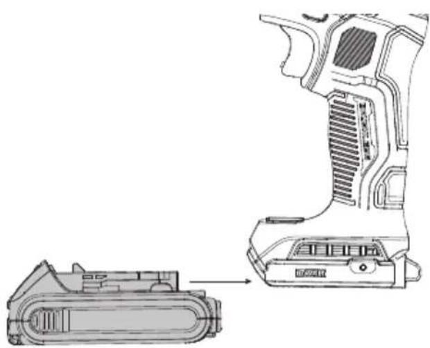
natural_image
Technical line drawing of a mechanical device with an exploded view showing internal components (no text or symbols)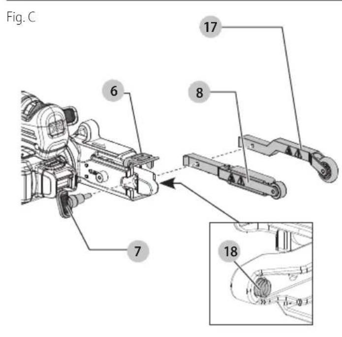
text_image
Fig. C 6 7 8 17 18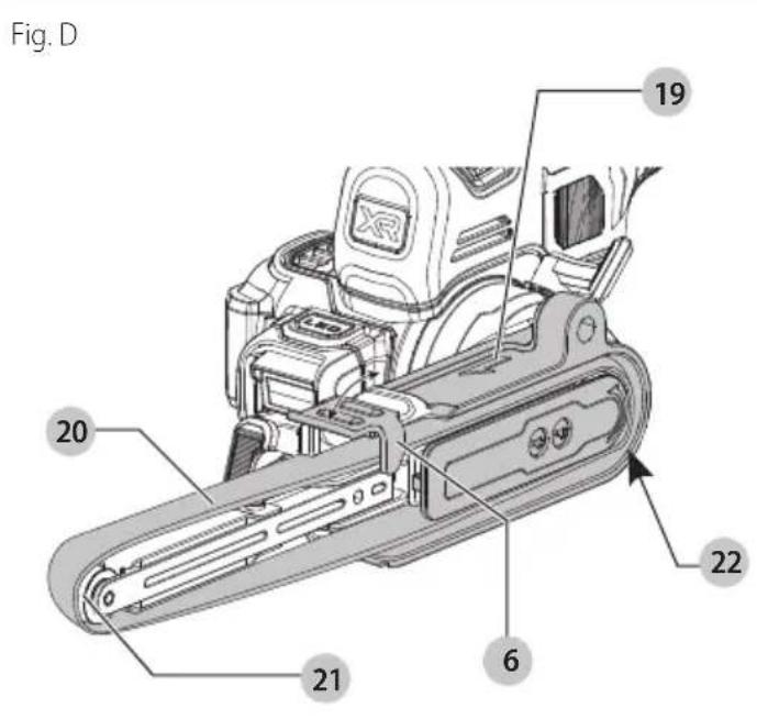
text_image
Fig. D 19 20 21 6 22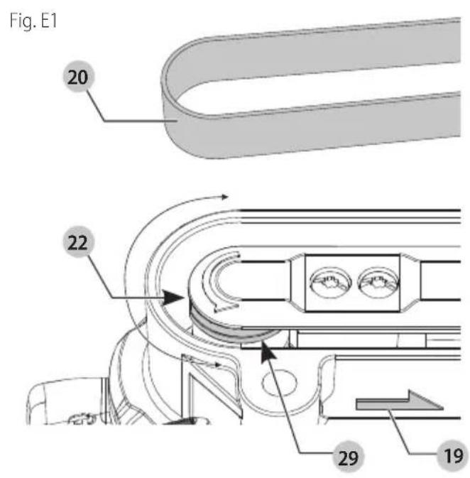
text_image
Fig. E1 20 22 29 19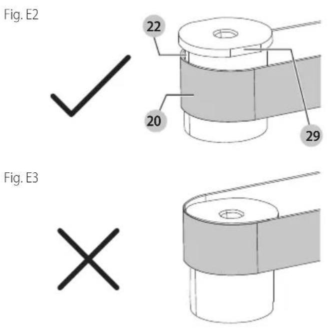
text_image
Fig. E2 22 20 29 Fig. E3 ×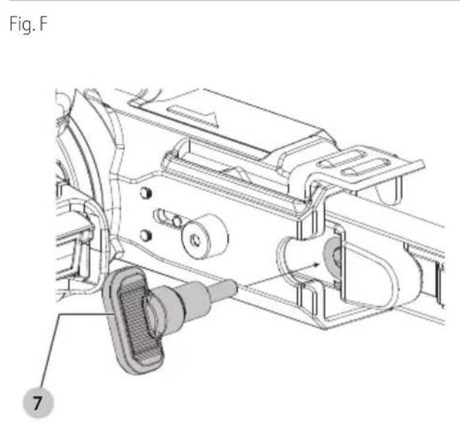
text_image
Fig. F 7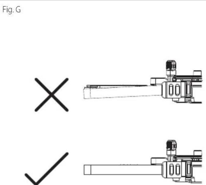
text_image
Fig. G × ✓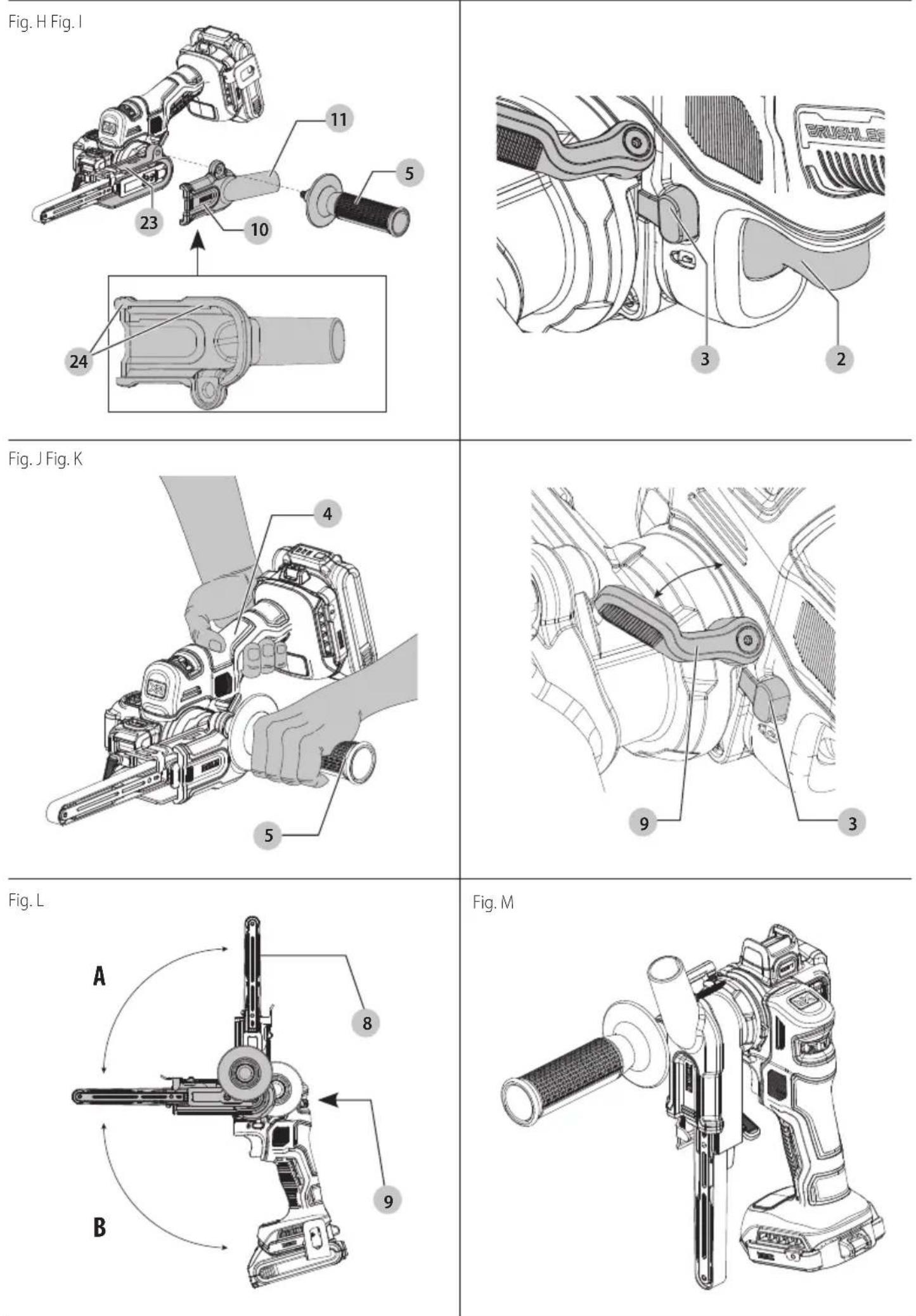
BÅNDFIL DCM200
Tillykke!
natural_image
Technical line drawing of a mechanical device with no visible text or symbolsInstallation of Tool Connect™ Chip
natural_image
Technical line drawing of a mechanical device with no visible text or symbolsYou have chosen a DEWALT tool. Years of experience, thorough product development and innovation make DEWALT one of the most reliable partners for professional power tool users.
Technical Data
| DCM200 | ||
| Voltage V | DC | 18 |
| Type 1 | ||
| Battery type Li-Ion | ||
| No-load speed m/min 600-1700 | ||
| Belt size | mm | 13 x 457 |
| Weight kg 1.3 | ||
Noise values and/or vibration values (triax vector sum) according to EN62841-2-4:
| L_PA (emission sound pressure level) dB(A) 74 | ||
| L_WA (sound power level) | dB(A) 82 | |
| K (uncertainty for the given sound level) | dB(A) | 3 |
| Vibration emission value a_h = | m/s2 | <2.5 |
| Uncertainty K = | m/s2 | 1.5 |
The vibration and/or noise emission level given in this information sheet has been measured in accordance with a standardised test given in EN62841 and may be used to compare one tool with another. It may be used for a preliminary assessment of exposure.
WARNING: The declared vibration and/or noise emission I represents the main applications of the tool. However, if the tool is used for different applications, with different accessories or is poorly maintained, the vibration and/or noise emission may differ. This may significantly increase the exposure level over the total working period.
An estimation of the level of exposure to vibration and/or noise should also take into account the times when the tool is switched off or when it is running but not actually doing the job. This may significantly reduce the exposure level over the total working period.
Identify additional safety measures to protect the operator from the effects of vibration and/or noise such as: maintain the tool and the accessories, keep the hands warm (relevant for vibration), organisation of work patterns.
EC-Declaration of Conformity
Machinery Directive
CE
Bandfile
DCM200
DEWALT declares that these products described under
Technical Data are in compliance with:
2006/42/EC, EN62841-1:2015+A11:2022, EN62841-2-4:2014 + AC:2015.
These products also comply with Directive 2014/30/EU and 2011/65/EU. For more information, please contact DEWALT at the following address or refer to the back of the manual.
The undersigned is responsible for compilation of the technical file and makes this declaration on behalf of DEWALT.

text_image
Mr. BergulMarkus Rompel
Vice-President Engineering, PTE-Europe
65510, Idstein, Germany
28.04.2023
DECLARATION OF CONFORMITY THE SUPPLY OF MACHINERY (SAFETY)
REGULATIONS 2008

Bandfile
DCM200
DEWALT declares that these products described under
Technical Data are in compliance with:
The Supply of Machinery (Safety) Regulations, 2008, S.I. 2008/1597 (as amended),
EN62841-1:2015+A11:2022, EN62841-2-4:2014 + AC:2015.
These products conform to the following UK Regulations:
Electromagnetic Compatibility Regulations, 2016, S.I.2016/1091 (as amended).
The Restriction of the Use of Certain Hazardous Substances in Electrical and Electronic Equipment Regulations 2012, S.I. 2012/3032 (as amended).
For more information, please contact DEWALT at the following address or refer to the back of the manual.
The undersigned is responsible for compilation of the technical file and makes this declaration on behalf of DEWALT.

natural_image
Simple line drawing of a curved line with intersecting strokes (no text or symbols)Karl Evans
Vice President Professional Power Tools EANZ GTS
DEWALT UK, 270 Bath Road, Slough
Berkshire, SL1 4DX
England
28.04.2023
| Batteries Chargers/Charge Times (Minutes)*** | |||||||||||||
| Cat # V | DC | Ah Weight (kg) | DCB104 DCB107 | DCB112/DCB1102 | DCB113 | DCB115/DCB1104 | DCB116 DCB117 DCB118 DCB132 DCB119 | ||||||
| DCB546 | 18/54 | 6.0/2.0 | 1.08 | 60 | 270 | 170 | 140 | 90 | 80 | 40 | 60 | 90 | X |
| DCB547/G | 18/54 | 9.0/3.0 | 1.46 | 75* | 420 | 270 | 220 | 135* | 110* | 60 | 75* | 135* | X |
| DCB548 | 18/54 | 12.0/4.0 | 1.46 | 120 | 540 | 350 | 300 | 180 | 150 | 80 | 120 | 180 | X |
| DCB181 | 18 | 1.5 | 0.35 | 22 | 70 | 45 | 35 | 22 | 22 | 22 | 22 | 22 | 45 |
| DCB182 | 18 | 4.0 | 0.61 | 60/40** | 185 | 120 | 100 | 60 | 60/45** | 60/40** | 60/40** | 60 | 120 |
| DCB183 | 18 | 2.0 | 0.40 | 30 | 90 | 60 | 50 | 30 | 30 | 30 | 30 | 30 | 60 |
| DCB184/B | 18 | 5.0 | 0.62 | 75/50** | 240 | 150 | 120 | 75 | 75/60** | 75/50** | 75/50** | 75 | 150 |
| DCB185 | 18 | 1.3 | 0.35 | 22 | 60 | 40 | 30 | 22 | 22 | 22 | 22 | 22 | 40 |
| DCB187 | 18 | 3.0 | 0.54 | 45 | 140 | 90 | 70 | 45 | 45 | 45 | 45 | 45 | 90 |
| DCB189 | 18 | 4.0 | 0.54 | 60 | 185 | 120 | 100 | 60 | 60 | 60 | 60 | 60 | 120 |
| DCBP034/G | 18 | 1.7 | 0.32 | 27 | 82 | 50 | 40 | 27 | 27 | 27 | 27 | 27 | 50 |
| DCBP518 | 18 | 5.0 | 0.75 | 50 | 240 | 150 | 120 | 75 | 60 | 50 | 50 | 75 | 150 |
*Date code 201811475B or later
**Date code 201536 or later
***Battery charge times matrix provided for guidance only; charge times will vary depending on temperature and condition of batteries.

WARNING: To reduce the risk of injury, read the instruction manual.
Definitions: Safety Guidelines
The definitions below describe the level of severity for each signal word. Please read the manual and pay attention to these symbols.
DANGER: Indicates an imminently hazardous situation which, if not avoided, will result in death or serious injury.
WARNING: Indicates a potentially hazardous situation which, if not avoided, could result in death or serious injury.
CAUTION: Indicates a potentially hazardous situation, if not avoided, may result in minor or moderate injury.
NOTICE: Indicates a practice not related to personal injury which, if not avoided, may result in property damage.
Diagnates risk of electric shock.
Diabetes risk of fire.
GENERAL POWER TOOL SAFETY WARNINGS
WARNING: Read all safety warnings, instructions, indications and specifications provided with this
power tool. Failure to follow all instructions listed below may result in electric shock, fire and/or serious injury.
SAVE ALL WARNINGS AND INSTRUCTIONS FOR FUTURE REFERENCE
The term "power tool" in the warnings refers to your mains-operated (corded) power tool or battery-operated (cordless) power tool.
1) Work Area Safety
a) Keep work area clean and well lit. Cluttered or dark areas invite accidents.
b) Do not operate power tools in explosive atmospheres, such as in the presence of flammable liquids, gases or dust. Power tools create sparks which may ignite the dust or fumes.
c) Keep children and bystanders away while operating a power tool. Distractions can cause you to lose control.
2) Electrical Safety
a) Power tool plugs must match the outlet. Never modify the plug in any way. Do not use any adapter plugs with earthed (grounded) power tools.
Unmodified plugs and matching outlets will reduce risk of electric shock.
b) Avoid body contact with earthed or grounded surfaces, such as pipes, radiators, ranges and refrigerators. There is an increased risk of electric shock if your body is earthed or grounded.
c) Do not expose power tools to rain or wet conditions. Water entering a power tool will increase the risk of electric shock.
d) Do not abuse the cord. Never use the cord for carrying, pulling or unplugging the power tool. Keep cord away from heat, oil, sharp edges or moving parts. Damaged or entangled cords increase the risk of electric shock.
e) When operating a power tool outdoors, use an extension cord suitable for outdoor use. Use of a cord suitable for outdoor use reduces the risk of electric shock.
f) If operating a power tool in a damp location is unavoidable, use a residual current device (RCD) protected supply. Use of an RCD reduces the risk of electric shock.
3) Personal Safety
a) Stay alert, watch what you are doing and use common sense when operating a power tool. Do not use a power tool while you are tired or under the influence of drugs, alcohol or medication. A moment of inattention while operating power tools may result in serious personal injury.
b) Use personal protective equipment. Always wear eye protection. Protective equipment such as a dust mask, non-skid safety shoes, hard hat or hearing protection used for appropriate conditions will reduce personal injuries.
c) Prevent unintentional starting. Ensure the switch is in the off position before connecting to power source and/or battery pack, picking up or carrying the tool. Carrying power tools with your finger on the switch or energising power tools that have the switch on invites accidents.
d) Remove any adjusting key or wrench before turning the power tool on. A wrench or a key left attached to a rotating part of the power tool may result in personal injury.
e) Do not overreach. Keep proper footing and balance at all times. This enables better control of the power tool in unexpected situations.
f) Dress properly. Do not wear loose clothing or jewellery. Keep your hair and clothing away from moving parts. Loose clothes, jewellery or long hair can be caught in moving parts.
g) If devices are provided for the connection of dust extraction and collection facilities, ensure these are connected and properly used. Use of dust collection can reduce dust-related hazards.
h) Do not let familiarity gained from frequent use of tools allow you to become complacent and ignore tool safety principles. A careless action can cause severe injury within a fraction of a second.
4) Power Tool Use and Care
a) Do not force the power tool. Use the correct power tool for your application. The correct power tool will do the job better and safer at the rate for which it was designed.
b) Do not use the power tool if the switch does not turn it on and off. Any power tool that cannot be controlled with the switch is dangerous and must be repaired.
c) Disconnect the plug from the power source and/or remove the battery pack, if detachable, from the power tool before making any adjustments, changing accessories, or storing power tools. Such preventive safety measures reduce the risk of starting the power tool accidentally.
d) Store idle power tools out of the reach of children and do not allow persons unfamiliar with the power tool or these instructions to operate the power tool. Power tools are dangerous in the hands of untrained users.
e) Maintain power tools and accessories. Check for misalignment or binding of moving parts, breakage of parts and any other condition that may affect the
power tool's operation. If damaged, have the power tool repaired before use. Many accidents are caused by poorly maintained power tools.
f) Keep cutting tools sharp and clean. Properly maintained cutting tools with sharp cutting edges are less likely to bind and are easier to control.
g) Use the power tool, accessories and tool bits, etc. in accordance with these instructions, taking into account the working conditions and the work to be performed. Use of the power tool for operations different from those intended could result in a hazardous situation.
h) Keep handles and grasping surfaces dry, clean and free from oil and grease. Slippery handles and grasping surfaces do not allow for safe handling and control of the tool in unexpected situations.
5) Battery Tool Use and Care
a) Recharge only with the charger specified by the manufacturer. A charger that is suitable for one type of battery pack may create a risk of fire when used with another battery pack.
b) Use power tools only with specifically designated battery packs. Use of any other battery packs may create a risk of injury and fire.
c) When battery pack is not in use, keep it away from other metal objects, like paper clips, coins, keys, nails, screws or other small metal objects, that can make a connection from one terminal to another. Shorting the battery terminals together may cause burns or a fire.
d) Under abusive conditions, liquid may be ejected from the battery; avoid contact. If contact accidentally occurs, flush with water. If liquid contacts eyes, additionally seek medical help. Liquid ejected from the battery may cause irritation or burns.
e) Do not use a battery pack or tool that is damaged or modified. Damaged or modified batteries may exhibit unpredictable behaviour resulting in fire, explosion or risk of injury.
f) Do not expose a battery pack or tool to fire or excessive temperature. Exposure to fire or temperature above 130 °C may cause explosion.
g) Follow all charging instructions and do not charge the battery pack or tool outside the temperature range specified in the instructions. Charging improperly or at temperatures outside the specified range may damage the battery and increase the risk of fire.
6) Service
a) Have your power tool serviced by a qualified repair person using only identical replacement parts. This will ensure that the safety of the power tool is maintained.
b) Never service damaged battery packs. Service of battery packs should only be performed by the manufacturer or authorised service providers.
Belt Sander Supplemental Safety Warnings
• Always use proper eye protection and a respirator when sanding.
- Use clamps or another practical way to secure and support the workpiece to a stable platform. Holding the workpiece by hand or against your body leaves it unstable and may lead to loss of control.
- Sanding of lead-based paint is not recommended. See Sanding Lead-Based Paint for additional information before sanding paint.
- Clean your tool out periodically.
- Do not wet sand with this sander. Liquids may enter the motor housing and cause damage to the belt sander.
- Static shocks are possible in dry areas or when the relative humidity of the air is low. This is only temporary and does not affect the use of the belt sander. To reduce the frequency of static shocks, add moisture to the air with a console, or installed humidifier.
- If included with tool, empty dust bag frequently. Especially when sanding resin-coated surfaces such as polyurethane, varnish, shellac, etc. The accumulation of fine sanding dust particles may self-ignite and cause fire.
- Do not operate this tool for long periods of time.
Vibration caused by the operating action of this tool may cause permanent injury to fingers, hands, and arms. Use gloves to provide extra cushion, take frequent rest periods, and limit daily time of use.
- Sanding of lead-based paint, chemically pressure treated lumber or other materials that may contain carcinogens is not recommended. Sanding of these materials should only be performed by a professional.
- ALWAYS disconnect tool from the power source before changing abrasive belts. Such preventive safety measures reduce the risk of starting the power tool accidentally.
- ALWAYS maintain a firm grip with both hands on the belt sander handles to prevent loss of control.
- ALWAYS keep fingers away from the moving belt and areas where the belt enters the housing to avoid severe abrasion.
- Do not operate belt sander without all guards and covers securely in place.
- To avoid injury, do not use this tool in a stand that would invert it for use as a stationary belt sander. This tool is not made for that application.
Specific Safety Warnings and Instructions: Sanders
Sanding Lead-Based Paint
Sanding of lead-based paint is NOT RECOMMENDED due to the difficulty of controlling the contaminated dust. The greatest danger of lead poisoning is to children and pregnant women.
Since it is difficult to identify whether or not a paint contains lead without a chemical analysis, we recommend the following precautions when sanding any paint:
Personal Safety
- No children or pregnant women should enter the work area where the paint sanding is being done until all clean-up is completed.
- A dust mask or respirator should be worn by all persons entering the work area. The filter should be replaced daily or whenever the wearer has difficulty breathing.
NOTE: Only those dust masks suitable for working with lead paint dust and fumes should be used. Ordinary painting masks do not offer this protection. See your local hardware dealer for the proper mask.
- NO EATING, DRINKING or SMOKING should be done in the work area to prevent ingesting contaminated paint particles. Workers should wash and clean up BEFORE eating, drinking or smoking. Articles of food, drink, or smoking should not be left in the work area where dust would settle on them.
Environmental Safety
- Paint should be removed in such a manner as to minimize the amount of dust generated.
- Areas where paint removal is occurring should be sealed with plastic sheeting of 4 mils thickness.
- Sanding should be done in a manner to reduce tracking of paint dust outside the work area.
Cleaning and Disposal
- All surfaces in the work area should be vacuumed and thoroughly cleaned daily for the duration of the sanding project. Vacuum filter bags should be changed frequently.
- Plastic drop cloths should be gathered up and disposed of along with any dust chips or other removal debris. They should be placed in sealed refuse receptacles and disposed of through regular trash pick-up procedures. During clean-up, children and pregnant women should be kept away from the immediate work area.
- All toys, washable furniture and utensils used by children should be washed thoroughly before being used again.
Residual Risks
In spite of the application of the relevant safety regulations and the implementation of safety devices, certain residual risks cannot be avoided. These are:
- Impairment of hearing.
- Risk of personal injury due to flying particles.
- Risk of burns due to accessories becoming hot during operation.
- Risk of personal injury due to prolonged use.
SAVE THESE INSTRUCTIONS
Chargers
DEWALT chargers require no adjustment and are designed to be as easy as possible to operate.
Electrical Safety
The electric motor has been designed for one voltage only. Always check that the battery pack voltage corresponds to the voltage on the rating plate. Also make sure that the voltage of your charger corresponds to that of your mains.

Your DEWALT charger is double insulated in accordance with EN60335; therefore, no earth wire is required.
If the supply cord is damaged, it must be replaced only by DEWALT or an authorised service organisation.
Mains Plug Replacement (U.K. & Ireland Only)
If a new mains plug needs to be fitted:
• Safely dispose of the old plug.
- Connect the brown lead to the live terminal in the plug.
- Connect the blue lead to the neutral terminal.
WARNING: No connection is to be made to the terminal.
Follow the fitting instructions supplied with good quality plugs. Recommended fuse: 3 A.
Using an Extension Cable
An extension cord should not be used unless absolutely necessary. Use an approved extension cable suitable for the power input of your charger (see Technical Data). The minimum conductor size is 1 mm^2 ; the maximum length is 30 m.
When using a cable reel, always unwind the cable completely.
Important Safety Instructions for All Battery Chargers
save THEsE InsTRUCTIONS: This manual contains important safety and operating instructions for compatible battery chargers (refer to Technical Data).
- Before using charger, read all instructions and cautionary markings on charger, battery pack, and product using battery pack.
WARNING: Shock hazard. Do not allow any liquid to get inside charger. Electric shock may result.
WARNING: We recommend the use of a residual current rating with a residual current rating of 30mA or less.
CAUTION: Burn hazard. To reduce the risk of injury, charge only DEWALT rechargeable batteries. Other types of batteries may burst, causing personal injury and damage.
CAUTION: Children should be supervised to ensure that they do not play with the appliance.
NOTICE: Under certain conditions, with the charger plugged into the power supply, the exposed charging contacts inside the charger can be shorted by foreign material. Foreign materials of a conductive nature such as, but not limited to, steel wool, aluminum foil or any buildup of metallic particles should be kept away from charger cavities. Always unplug the charger from the power supply when there is no battery pack in the cavity. Unplug charger before attempting to clean.
- DO NOT attempt to charge the battery pack with any chargers other than the ones in this manual. The charger and battery pack are specifically designed to work together.
• These chargers are not intended for any uses other than charging DEWALT rechargeable batteries. Any other uses may result in risk of fire, electric shock or electrocution. -
Do not expose charger to rain or snow.
-
Pull by plug rather than cord when disconnecting charger. This will reduce risk of damage to electric plug and cord.
- Make sure that cord is located so that it will not be stepped on, tripped over, or otherwise subjected to damage or stress.
- Do not use an extension cord unless it is absolutely necessary. Use of improper extension cord could result in risk of fire, electric shock, or electrocution.
- Do not place any object on top of charger or place the charger on a soft surface that might block the ventilation slots and result in excessive internal heat. Place the charger in a position away from any heat source. The charger is ventilated through slots in the top and the bottom of the housing.
- Do not operate charger with damaged cord or plug—have them replaced immediately.
- Do not operate charger if it has received a sharp blow, been dropped, or otherwise damaged in any way. Take it to an authorised service centre.
- Do not disassemble charger; take it to an authorised service centre when service or repair is required. Incorrect reassembly may result in a risk of electric shock, electrocution or fire.
- In case of damaged power supply cord, the supply cord must be replaced immediately by the manufacturer, its service agent or similar qualified person to prevent any hazard.
- Disconnect the charger from the outlet before attempting any cleaning. This will reduce the risk of electric shock. Removing the battery pack will not reduce this risk.
- NEVER attempt to connect two chargers together.
- The charger is designed to operate on standard 230V household electrical power. Do not attempt to use it on any other voltage. This does not apply to the vehicular charger.
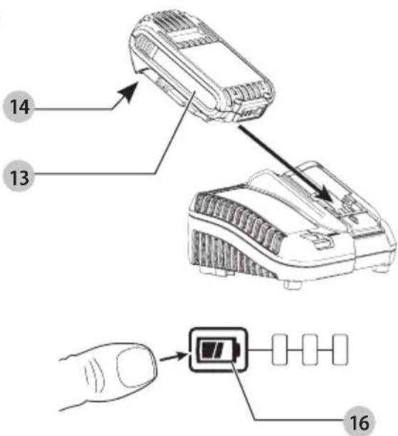
Charging a Battery (Fig. B)
NOTE: To ensure maximum performance and life of lithium-ion battery packs, charge the battery pack fully before first use.
- Plug the charger into an appropriate outlet before inserting battery pack.
- Insert the battery pack 13 into the charger, making sure the battery pack is fully seated in the charger. The red (charging) light will blink repeatedly indicating that the charging process has started.
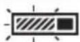
- The Stage 1 charging blink indicator represents the charge process that charges the majority of the battery's capacity. Stage 2 charging blink indicator represents the remainder, or top off charge process, for the battery to reach full capacity.
- The completion of charge for Stage 1 or Stage 2 will be indicated by the stage's light remaining ON continuously. The battery pack is fully charged when both Stage 1 and Stage 2 charging lights remain ON continuously, and it may be removed and used at this time or left in the charger.
NOTE: To remove the battery pack, some chargers require the battery pack release button 14 to be pressed.
Refer to the indicators below for the charge status of the battery pack.
Indicators
Stage 1 Charging


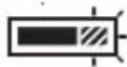
Stage 2 Charging


Fully Charged


Hot/Cold Pack Delay*


* The red light will continue to blink, but a yellow indicator light will be illuminated during this operation. Once the battery pack has reached an appropriate temperature, the yellow light will turn off and the charger will resume the charging procedure. The compatible charger(s) will not charge a faulty battery pack. The charger will indicate faulty battery by refusing to light.
NOTE: This could also mean a problem with a charger.
If the charger indicates a problem, take the charger and battery pack to be tested at an authorised service centre.
Hot/Cold Pack Delay
When the charger detects a battery pack that is too hot or too cold, it automatically starts a Hot/Cold Pack Delay, suspending charging until the battery pack has reached an appropriate temperature. The charger then automatically switches to the pack charging mode. This feature ensures maximum battery pack life.
A cold battery pack will charge at a slower rate than a warm battery pack. The battery pack will charge at that slower rate throughout the entire charging cycle and will not return to maximum charge rate even if the battery pack warms.
The DCB118 charger is equipped with an internal fan designed to cool the battery pack. The fan will turn on automatically when the battery pack needs to be cooled. Never operate the charger if the fan does not operate properly or if ventilation slots are blocked. Do not permit foreign objects to enter the interior of the charger.
Electronic Protection System
XR Li-Ion tools are designed with an Electronic Protection System that will protect the battery pack against overloading, overheating or deep discharge.
The tool will automatically turn off if the Electronic Protection System engages. If this occurs, place the lithium-ion battery pack on the charger until it is fully charged.
Wall Mounting
These chargers are designed to be wall mountable or to sit upright on a table or work surface. If wall mounting, locate the charger within reach of an electrical outlet, and away from a corner or other obstructions which may impede air flow. Use the back of the charger as a template for the location of the mounting screws on the wall. Mount the charger securely using drywall screws (purchased separately) at least 25.4 mm long with a screw head diameter of 7–9 mm, screwed into wood to an optimal depth leaving approximately 5.5 mm of the screw exposed. Align the slots on the back of the charger with the exposed screws and fully engage them in the slots.
Charger Cleaning Instructions
WARNING: Shock hazard. Disconnect the charger from the AC outlet before cleaning. Dirt and grease may be removed from the exterior of the charger using a cloth or soft non-metallic brush. Do not use water or any cleaning solutions. Never let any liquid get inside the tool; never immerse any part of the tool into a liquid.
Battery Packs
Important Safety Instructions for All Battery Packs
When ordering replacement battery packs, be sure to include catalogue number and voltage.
The battery pack is not fully charged out of the carton. Before using the battery pack and charger, read the safety instructions below. Then follow charging procedures outlined.
READ ALL INSTRUCTIONS
- Do not charge or use battery in explosive atmospheres, such as in the presence of flammable liquids, gases or dust. Inserting or removing the battery from the charger may ignite the dust or fumes.
- Never force battery pack into charger. Do not modify battery pack in any way to fit into a non-compatible charger as battery pack may rupture, causing serious personal injury.
• Charge the battery packs only in DEWALT chargers.
• DO NOT splash or immerse in water or other liquids. - Do not store or use the tool and battery pack in locations where the temperature may fall below 4 °C (39.2 °F) (such as outside sheds or metal buildings in winter), or reach or exceed 40 °C (104 °F) (such as outside sheds or metal buildings in summer).
- Do not incinerate the battery pack even if it is severely damaged or is completely worn out. The battery pack can explode in a fire. Toxic fumes and materials are created when lithium-ion battery packs are burned.
- If battery contents come into contact with the skin, immediately wash area with mild soap and water. If battery liquid gets into the eye, rinse water over the open eye for 15 minutes or until irritation ceases. If medical attention is needed, the battery electrolyte is composed of a mixture of liquid organic carbonates and lithium salts.
- Contents of opened battery cells may cause respiratory irritation. Provide fresh air. If symptoms persist, seek medical attention.
WARNING: Burn hazard. Battery liquid may be flammable if exposed to spark or flame.
WARNING: Never attempt to open the battery pack for any reason. If battery pack case is cracked or damaged, do not insert into charger. Do not crush, drop or damage battery pack. Do not use a battery pack or charger that
has received a sharp blow, been dropped, run over or damaged in any way (i.e., pierced with a nail, hit with a hammer, stepped on). Electric shock or electrocution may result. Damaged battery packs should be returned to service centre for recycling.
WARNING: Fire hazard. Do not store or carry the heavy pack so that metal objects can contact
exposed battery terminals. For example, do not place the battery pack in aprons, pockets, tool boxes, product kit boxes, drawers, etc., with loose nails, screws, keys, etc.
CAUTION: When not in use, place tool on its side on a double surface where it will not cause a tripping
or falling hazard. Some tools with large battery packs will stand upright on the battery pack but may be easily knocked over.
Transportation
WARNING: Fire hazard. Transporting batteries can possibly cause fire if the battery terminals inadvertently come into contact with conductive materials. When transporting batteries, make sure that the battery terminals are protected and well-insulated from materials that could contact them and cause a short circuit. NOTE: Lithium-ion batteries should not be put in checked baggage.
DEWALT batteries comply with all applicable shipping regulations as prescribed by industry and legal standards, which include UN Recommendations on the Transport of Dangerous Goods; International Air Transport Association (IATA) Dangerous Goods Regulations; International Maritime Dangerous Goods (IMDG) Regulations; and the European Agreement Concerning The International Carriage of Dangerous Goods by Road (ADR). Lithium-ion cells and batteries have been tested to section 38.3 of the UN Recommendations on the Transport of Dangerous Goods Manual of Tests and Criteria.
In most instances, shipping a DEWALT battery pack will be excepted from being classified as a fully regulated Class 9 Hazardous Material. In general, only shipments containing a lithium-ion battery with an energy rating greater than 100 Watt Hours (Wh) will require being shipped as fully regulated Class 9. All lithium-ion batteries have the Wh rating marked on the pack. Furthermore, due to regulation complexities, DEWALT does not recommend air shipping lithium-ion battery packs alone regardless of Wh rating. Shipments of tools with batteries (combo kits) can be air shipped as excepted if the Wh rating of the battery pack is no greater than 100 Wh.
Regardless of whether a shipment is considered excepted or fully regulated, it is the shipper's responsibility to consult the latest regulations for packaging, labeling/marking and documentation requirements.
The information provided in this section of the manual is provided in good faith and believed to be accurate at the time the document was created. However, no warranty, expressed or implied, is given. It is the buyer's responsibility to ensure that its activities comply with the applicable regulations.
Transporting the FLEXVOLT™ Battery
The DEWALT FLEXVOLT® battery has two modes: Use and Transport.
Use Mode: When the FLEXVOLT™ battery stands alone or is in a DEWALT 18V product, it will operate as an 18V battery. When the FLEXVOLT™ battery is in a 54V or a 108V (two 54V batteries) product, it will operate as a 54V battery.
Transport Mode: When the cap is attached to the FLEXVOLT™ battery, the battery is in Transport mode. Keep the cap for shipping.
When in Transport mode, strings of cells are electrically disconnected within the pack, resulting in 3 batteries with a
natural_image
Technical line drawing of a mechanical component with no visible text or symbolslower Watt hour (Wh) rating as compared to 1 battery with a higher Watt hour rating. This increased quantity of 3 batteries with the lower Watt hour rating can exempt the pack from certain shipping regulations that are imposed upon the higher Watt hour batteries.
For example, the Transport Wh rating might indicate
3 x 36 Wh, meaning
3 batteries of 36 Wh each.
The Use Wh rating might indicate 108 Wh (1 battery implied).
Example of Use and Transport Label Marking

Use: 108 Wh
Transport: 3x36 Wh
Storage Recommendations
- The best storage place is one that is cool and dry away from direct sunlight and excessive heat or cold. For optimum battery performance and life, store battery packs at room temperature when not in use.
- For long storage, it is recommended to store a fully charged battery pack in a cool, dry place out of the charger for optimal results.
NOTE: Battery packs should not be stored completely depleted of charge. The battery pack will need to be recharged before use.
Labels on Charger and Battery Pack
In addition to the pictographs used in this manual, the labels on the charger and the battery pack may show the following pictographs:

Read instruction manual before use.

Refer to Technical Data for charging time.

Do not probe with conductive objects.

Do not charge damaged battery packs.

Do not expose to water.


Have defective cords replaced immediately.

Charge only between 4 °C and 40 °C.

Only for indoor use.

Discard the battery pack with due care for the environment.

Charge DEWALT battery packs only with designated DEWALT chargers. Charging battery packs other than the designated DEWALT batteries with a DEWALT charger may make them burst or lead to other dangerous situations.

Do not incinerate the battery pack.

USE (without transport cap). Example: Wh rating indicates 108 Wh (1 battery with 108 Wh).

TRANSPORT (with built-in transport cap). Example: Wh rating indicates 3 x 36 Wh (3 batteries of 36 Wh).
Battery Type
These battery packs may be used: DCB181, DCB182, DCB183, DCB184, DCB184B, DCB185, DCB187, DCB189, DCBP034, DCBP034G, DCBP518, DCB546, DCB547, DCB547G, DCB548. Refer to Technical Data for more information.
Package Contents
The package contains:
1Bandfile
1 Side Handle
2 80 Grit Abrasive Belt
1 Offset Accessory Arm
1 Dust Shroud
1Charger
1 Li-lon battery pack (C1, D1, E1, G1, H1, L1, M1, P1, Q1, S1, T1, U1, X1, Y1, Z1 models)
2 Li-Ion battery packs (C2, D2, E2, G2, H2, L2, M2, P2, Q2, S2, T2, U2, X2, Y2, Z2 models)
3 Li-lon battery packs (C3, D3, E3, G3, H3, L3, M3, P3, Q3, S3, T3, U3, X3, Y3, Z3 models)
1 Instructionmanual
NOTE: Battery packs, chargers and kitboxes are not included with N models. Battery packs and chargers are not included with NT models. B models include Bluetooth® battery packs.
NOTE: The Bluetooth ^® word mark and logos are registered trademarks owned by the Bluetooth ^® , SIG, Inc. and any use of such marks by DEWALT is under license. Other trademarks and trade names are those of their respective owners.
- Check for damage to the tool, parts or accessories which may have occurred during transport.
• Take the time to thoroughly read and understand this manual prior to operation.
Markings on Tool
The following pictograms are shown on the tool:

Read instruction manual before use.

Wear ear protection.

Wear eye protection.

Wear respiratory protection.

Visible radiation. Do not stare into light.

Hot surface. Risk of burns. Do not touch.

Warning
Date Code Position (Fig. A)
The production date code 15 consists of a 4-digit year followed by a 2-digit week and is extended by a 2-digit factory code.
Description (Fig. A)
WARNING: Never modify the power tool or any part of it. Damage or personal injury could result.
1 Variable speed dial
2 Variable speed trigger
3 Lock-off button
4 Main handle
5 Side handle
6 Belt tensioning lever
7 Belt tracking screw
8 Straight arm
9 Lock lever
10 Dust shroud
11 Dust port
12 Rotatable LED light
13 Battery pack
14 Battery release button
15 Date code
Intended Use
This bandfile is designed for sanding wood, metal, plastic and painted surfaces.
For optimal balance, use 5Ah battery or smaller.
DO NOT use under wet conditions or in the presence of flammable liquids or gases.
This bandfile is a professional power tool.
DO NOT let children come into contact with the tool.
Supervision is required when inexperienced operators use this tool.
- Young children and the infirm. This appliance is not intended for use by young children or infirm persons without supervision.
- This product is not intended for use by persons (including children) suffering from diminished physical, sensory or mental abilities; lack of experience, knowledge or skills unless they are supervised by a person responsible for their safety. Children should never be left alone with this product.
ASSEMBLY AND ADJUSTMENTS
WARNING: To reduce the risk of serious personal injury, turn tool off and disconnect battery pack before making any adjustments or removing/installing attachments or accessories. An accidental start-up can cause injury.
WARNING: Use only DEWALT batteries and chargers.
Inserting and Removing the Battery Pack from the Tool (Fig. B)
nOTE: Make sure your battery pack 13 is fully charged.
To Install the Battery Pack into the Tool Handle
- Align the battery pack with the rails inside the tool's handle (Fig. B).
- Slide it into the handle until the battery pack is firmly seated in the tool and ensure that you hear the lock snap into place.
To Remove the Battery Pack from the Tool
- Press the battery release button 14 and firmly pull the battery pack out of the tool handle.
- Insert battery pack into the charger as described in the charger section of this manual.
Fuel Gauge Battery Packs (Fig. B)
Some DEWALT battery packs include a fuel gauge, which consists of three green LED lights that indicate the level of charge remaining in the battery pack.
To actuate the fuel gauge, press and hold the fuel gauge button 16. A combination of the three green LED lights will illuminate, designating the level of charge left. When the level of charge in the battery is below the usable limit, the fuel gauge will not illuminate and the battery will need to be recharged.
nOTE: The fuel gauge is only an indication of the charge left on the battery pack. It does not indicate tool functionality and is subject to variation based on product components, temperature and end-user application.
Fitting and Removing Sanding Arms (Fig. C, D)
13 mm x 457 mm (1/2" x 18") width belts can be installed with the optional arms that are designed for the corresponding belt widths.
Your tool is supplied with the following:
• A straight arm 8 (sanding width 13 mm).
• An offset arm 17 (sanding width 13 mm).
nOTE: Your tool comes with the straight arm already assembled.
Fitting
- Make sure that the belt tensioning lever 6 is in the position shown in Fig. C.
-
Loosen and remove the belt tracking screw 7.
-
Check that the spring 18 is located in its mounting hole.
- Position the arm 8 or 17 as shown.
- Fit the belt tracking screw and tighten it until the arm is aligned with the tool.
Removing
- Remove the sanding belt 20 (if present) as described in the Fitting and Removing Sanding Belts section.
- Loosen and remove the belt tracking screw 7.
- Remove the arm 8 or 17.
WARNING! Be careful not to lose the spring. WARNING: DO NOT touch the sanding arms after using as a high temperature may cause injury.
Fitting and Removing Sanding Belts
(Fig. D, E1–E3)
WARNING! The spring must be fitted. Be careful not to leave the spring.
Fitting
- Pull the belt tensioning lever 6 back.
- Make sure that the arrows on the inside of the sanding belt 20 face the same direction as the arrow 19 on the housing.
- Place the sanding belt over the rear pulley 22 first. The sanding belt should be placed under the shoulder 29 (Fig. E1, E2), then hook the other side over the front pulley 21.
- Move the belt tensioning lever to its original forward position.
- Adjust the belt tracking as described in the Adjusting the Sanding Belt Tracking section.
NOTE: The sanding belt should not ride on the shoulder of the rear pulley (Fig. E3). Be sure to place the sanding belt under the shoulder.
NOTE: The area surrounding the rear pulley 22 must be cleaned after each use due to the risk of gathering dust.
Removing
- Pull the belt tensioning lever 6 back to release the tension on the belt.
- Slide the sanding belt 20 off the pulleys.
Adjusting the Sanding Belt Tracking (Fig. C, D, F, G)
- Make sure that the sanding belt 20 is properly aligned with the straight arm 8.
- Switch the tool on and do a trial run at low speed.
- Turn the belt tracking screw 7 clockwise to move belt to right, or counterclockwise to move belt to left until the sanding belt runs straight along the length of the arm.
Adjusting the Arm Inclination (Fig. K, L)
The straight arm 8 or offset arm 17 can pivot and be fixed at any desired angle within the range A (102°) as shown in Fig. L. Make a comfortable working position by adjusting the angle.
- Loosen the lock lever 9 by flipping it downwards.
- Pivot the arm to the desired position.
- Secure the position of the arm firmly by flipping the lock lever up.
Attaching the Side Handle (Fig. H)
WARNING: This handle SHOULD BE USED AT ALL ITEMS to maintain complete control of the tool.
Always make sure the handle is tight.
Screw the side handle 5 tightly into the threaded mounting hole of the filehead body 23.
Attaching the Dust Shroud (Fig. H)
The DCM200DC dust shroud is included with this tool. This accessory connects to the tool's filehead body.
To attach the dust shroud 10, FIRST disconnect the battery from the tool.
- Place the ribs 24 of the dust shroud 10 along the groove of the filehead body 23.
- Position the dust port 11 against the filehead body to let the dust port hole align with the filehead body hole.
- Use the side handle 5 to tighten the dust shroud to the filehead body.
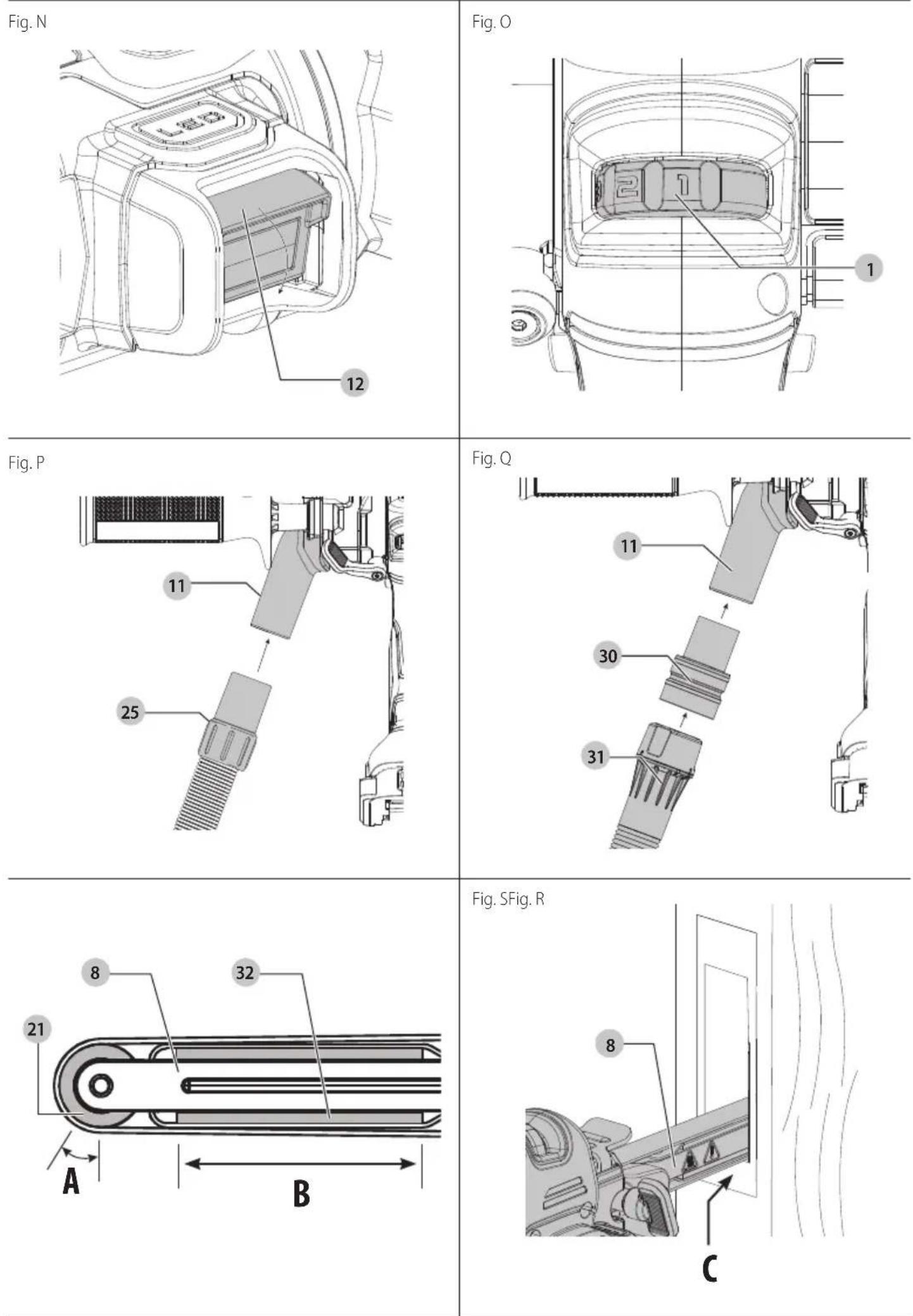
Attaching a Dust Extractor to the Dust Shroud (Fig. P, Q)
WARNING: Do not attach the dust port and connect the duct extractor when grinding or sanding metals.
WARNING: Risk of dust inhalation. To reduce the risk of personal injury, ALWAYS wear an approved dust mask.
WARNING: Collected sanding dust from sanding sander coatings (polyurethane, linseed oil, etc.) can self-ignite in dust extractor or elsewhere and cause fire. To reduce risk, strictly follow sander manual and coating manufacturer's instructions.
The DCM200DC dust shroud is compatible with the DWH161 DEWALT Universal Dust Extractor (sold separately).
- Friction-fit the dust port 11 to the hose 25 of the DWH161 Universal Dust Extractor.
If available, the DWV9170 adaptor 30 can be used to connect your tool to the DEWALT AirLock™ connection system (sold separately).
-
Push the AirLock™ connector 31 onto the DWV9170 adaptor.
-
Friction-fit the DWV9170 adaptor to the dust port.
OPERATION
Instructions for Use
WARNING: Always observe the safety instructions and applicable regulations.
WARNING: To reduce the risk of serious personal injury, turn tool off and disconnect battery pack before making any adjustments or removing/installing attachments or accessories. An accidental start-up can cause injury.
WARNING: DO NOT touch the filehead body during use as a high temperature may cause injury.
Proper Hand Position (Fig. J)
WARNING: To reduce the risk of serious personal injury, ALWAYS use proper hand position as shown.
WARNING: To reduce the risk of serious personal injury, ALWAYS hold securely in anticipation of a sudden reaction.
Proper hand position requires one hand on the main handle 4 and one hand on the side handle 5.
LED Worklight (Fig. A, N)
CAUTION: Do not stare into the LED worklight. Serious eye injury could result.
The rotatable LED worklight 12 can be adjusted at three levels through an angle of 60^ . When the tool is activated by depressing the variable speed trigger 2, the rotatable LED worklight will automatically turn on. The rotatable LED worklight will turn off 20 seconds after the variable speed trigger has been released.
NOTE: Be careful not to scratch the lens of the worklight as loss of illumination may occur. Use a dry cloth to wipe dirt off the lens of the worklight.
Variable Speed Dial (Fig. 0)
The variable speed dial 1 allows you to adapt the speed of the tool to the workpiece material.
The tool speed can be adjusted between 1 to 7.
Use a low speed setting when using a fine grit, when working with plastics or ceramics and when removing painted or varnished surfaces.
Use a high speed setting when using a coarse grit and when removing a lot of material.
- Set the variable speed dial 1 to the required setting.
Switching On and Off (Fig. A)
CAUTION: DO NOT pull the variable speed trigger hard without first unlocking the tool. Refer to the Lock-off Button section. This can cause a breakage to the variable speed trigger.
- To start the tool, pull the variable speed trigger 2.
- To turn the tool off, release the variable speed trigger.
Lock-off Button (Fig. I)
WARNING: To prevent accidental start-up, this tool is equipped with a lock-off button.
- To lock the tool, depress the lock-off button 3 to the locked position. When the lock-off button is in the locked position, the tool is locked and the variable speed trigger 2 cannot be pulled.
- To unlock the tool, depress the lock-off button 3 to the unlocked position.
NOTE: The tool is locked and the speed trigger can't be pulled while the arm is being pivoted to the storage position (beyond 102°).
Special Applications (Fig. A, R–V)
WARNING: To reduce the risk of fire or serious injury, understanding ignitable materials such as aluminum and magnesium.
WARNING! DO NOT allow bystanders in front of the tool warning in operation as there may be a risk of the sanding belt breaking and dislodging from the arm.
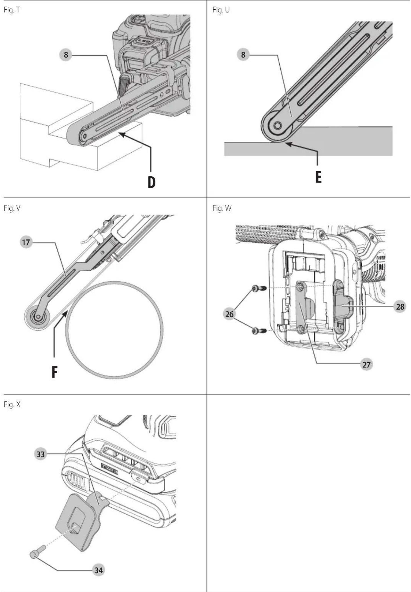
Straight Arm (Fig. R–U)
Use the straight arm 8 for general use, sanding, deburring, and slotting. Work should always be performed within range (A) of the front pulley 21 (Fig. R) or within range (B) of the platen 32, as shown on the straight arm (Fig. R).
- Refer to area C of the straight arm (Fig. S) for sanding in confined areas.
- Refer to areas D and E of the straight arm (Fig. T, U) for general sanding.
Offset Arm (Fig. V)
Where Supplied
- Use the offset arm 17 for sanding curved surfaces.
- Refer to area F (Fig. V) of the offset arm for sanding a curved surface.
Hints for Optimum Use
• Always hold the tool with both hands.
- Do not exert too much pressure on the tool.
- For best belt life, sand only with the bottom side of belt.
- Do not exert much force in line with the arm.
- Regularly check the condition of the sanding belt 20. Replace when necessary.
• Always sand with the grain of the wood.
- When sanding new layers of paint before applying another layer, use extra fine grit.
- Consult your retailer for more information on available accessories.
MAINTENANCE
Your power tool has been designed to operate over a long period of time with a minimum of maintenance. Continuous satisfactory operation depends upon proper tool care and regular cleaning.
WARNING: To reduce the risk of serious personal injury, turn tool off and disconnect battery pack before making any adjustments or removing/installing attachments or accessories. An accidental start-up can cause injury.
The charger and battery pack are not serviceable.
Tool Connect™ Chip (Fig. W)
WARNING: To reduce the risk of serious personal injury, turn unit off and remove the battery pack before making any adjustments or removing/installing attachments or accessories. An accidental start-up can cause injury.
Your tool is Tool Connect™ Chip ready and has a location for installation of a Tool Connect™ Chip.
Tool Connect™ Chip is an optional application for your smart device (such as a smart phone or tablet) that connects the device to utilize the mobile application for inventory management functions.
Refer to Tool Connect™ Chip Instruction Sheet for more information.
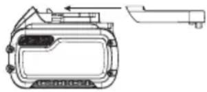
Installing the Tool Connect™ Chip
- Remove the retaining screws 26 that hold the Tool Connect™ Chip protective cover 27 into the tool.
- Remove the protective cover and insert the Tool Connect™ Chip into the empty pocket 28.
- Ensure that the Tool Connect™ Chip is flush with the housing. Secure it with the retaining screws and tighten the screws.
- Refer to Tool Connect™ Chip Instruction Sheet for further instructions.
Storage (Fig. K–M)
CAUTION: Be careful not to pinch your fingers when running the straight arm. Failure to do so may cause personal injury.
The straight arm 8 can be folded up to save on storage space as shown in Fig. M. The straight arm can move through an angle of up to 172°.
- Loosen the lock lever 9 by flipping it down. Pivot the arm at an angle of 102^ .
- Push the lock-off button 3, and then adjust the angle of the straight arm in the range B (102° to 172°) shown in Fig. L.
- Secure the lock lever by flipping it up to fix the arm.
NOTE: The tool is locked and the speed trigger can't be pulled while the arm is being pivoted to the storage position (beyond 102°).
Lubrication
Your power tool requires no additional lubrication.
Cleaning
WARNING: Electrical shock and mechanical hazard. Connect the electrical appliance from the power source before cleaning.
WARNING: To ensure safe and efficient operation, allows keep the electrical appliance and the ventilation slots clean.
WARNING: Never use solvents or other harsh chemicals for cleaning the non-metallic parts of the tool. These chemicals may weaken the materials used in these parts. Use a cloth dampened only with water and mild soap. Never let any liquid get inside the tool; never immerse any part of the tool into a liquid.
Ventilation slots can be cleaned using a dry, soft non-metallic brush and/or a suitable vacuum cleaner. Do not use water or any cleaning solutions. Wear approved eye protection and an approved dust mask.
Optional Accessories
WARNING: Since accessories, other than those offered by DEWALT, have not been tested with this product, use of such accessories with this tool could be hazardous. To reduce the risk of injury, only DEWALT-recommended accessories should be used with this product.
Consult your dealer for further information on the appropriate accessories.
Belt Hook (Fig. X)
Optional Accessory (Sold Separately)
WARNING: To reduce the risk of serious personal injury, ONLY use the tool's belt hook to hang the tool from a work belt. DO NOT use the belt hook for tethering or securing the tool to a person or object during use. DO NOT suspend tool overhead or suspend objects from the belt hook.
WARNING: To reduce the risk of serious personal injury, ensure the screw holding the belt hook is secure.
IMPORTanT: When attaching or replacing the belt hook, use only the mounting screw 34 that is provided. Be sure to securely tighten the screw.
The belt hook 33 can be attached to either side of the tool using only the screw provided, to accommodate left- or right-handed users. If the hook is not desired at all, it can be removed from the tool.
To move belt hook, remove the screw that holds the belt hook in place, then reassemble on the opposite side. Be sure to securely tighten the screw.
Protecting the Environment

Separate collection. Products and batteries marked with this symbol must not be disposed of with normal household waste.
Products and batteries contain materials that can be
recovered or recycled, reducing the demand for raw materials. Please recycle electrical products and batteries according to local provisions. Further information is available at www.2helpU.com.
Rechargeable Battery Pack
This long-life battery pack must be recharged when it fails to produce sufficient power on jobs that were easily done before. At the end of its technical life, discard it with due care for our environment:
- Run the battery pack down completely, then remove it from the tool.
- Li-lon cells are recyclable. Take them to your dealer or a local recycling station. The collected battery packs will be recycled or disposed of properly.
LIMA DE BANDA
DCM200
¡Enhorabuena!
natural_image
Technical line drawing of a mechanical device with no visible text or symbols| Charge phase 1 | — — | | [IMAGE] |
| Charge phase 2 | — | — | | [IMAGE] |
| Complètement rechargé | — | — | | [IMAGE] |
| Délai Bloc chaud/froid* | — — | — | | [IMAGE] |
natural_image
Technical line drawing of a mechanical component with no visible text or symbolsBloc-batterie rechargeable
natural_image
Technical line drawing of a mechanical device with no visible text or symbolsnatural_image
Technical line drawing of a mechanical component with mounting holes and a handle (no text or symbols)1 Li-ionaccu (modellen C1, D1, E1, G1, H1, L1, M1, P1, Q1, S1, T1, U1, X1, Y1, Z1)
2 Li-ionaccu's (modellen C2, D2, E2, G2, H2, L2, M2, P2, Q2, S2, T2, U2, X2, Y2, Z2)
3 Li-ionaccu's (modellen C3, D3, E3, G3, H3, L3, M3, P3, Q3, S3, T3, U3, X3, Y3, Z3)
1Gebruiksaanwijzing
Vice-President Engineering, PTE-Europe
natural_image
Technical line drawing of a mechanical component with no visible text or symbolsnatural_image
Technical line drawing of a mechanical component with no visible text or symbolsnatural_image
Technical line drawing of a mechanical component or housing with no visible text or symbolsVice-President Engineering, PTE-Europe