
Frigo EVP134A - Fridge DOMETIC - Free user manual and instructions
Find the device manual for free Frigo EVP134A DOMETIC in PDF.

| Brand | DOMETIC |
| Model | Frigo EVP134A |
| Product type | Refrigerator/Freezer for commercial vehicles |
| Intended use | Cooling of the loading area of commercial vehicles, stationary and while driving |
| Available variants | Refrigeration unit (+40 °C to 0 °C), constant temperature unit (+12 °C to 0 °C), freezing unit (+40 °C to -20 °C) |
| Power supply while driving | 12 V (via V-belt drive from vehicle engine) |
| Power supply stationary (optional) | 230 V (separate electric compressor, protected mains socket) |
| Main functions | Cooling, automatic and manual defrost, temperature control, keyboard lock, service hour display, alarm management |
| Control unit | Backlit display, adjustment keys, display of actual and setpoint temperatures |
| Setpoint temperature range (refrigeration) | 0 °C to +40 °C |
| Setpoint temperature range (freezing) | -20 °C to +40 °C |
| Setpoint temperature range (constant temperature) | 0 °C to +12 °C |
| Defrost | Automatic via air circulation or hot air (depending on version), manual defrost possible |
| Service and maintenance | Maintenance every 1000 service hours, fuse check, regular cleaning of door seals |
| Safety | Fuses, keyboard lock, 30 mA protection switch, instructions for mains connection |
| Displayed error messages | P1, P2, SEr, HR, LA (sensor failures, maintenance, temperature alarms) |
| After-sales service | Phone support +49 (0) 2572 879-966, repairs at authorized partners |
| Warranty | 24 months or 100,000 km (whichever comes first), requires regular maintenance |
| Disposal | Components to be returned to a disposal center at end of life |
Frequently Asked Questions - Frigo EVP134A DOMETIC
User questions about Frigo EVP134A DOMETIC
0 question about this device. Answer the ones you know or ask your own.
Ask a new question about this device
Download the instructions for your Fridge in PDF format for free! Find your manual Frigo EVP134A - DOMETIC and take your electronic device back in hand. On this page are published all the documents necessary for the use of your device. Frigo EVP134A by DOMETIC.
USER MANUAL Frigo EVP134A DOMETIC
natural_image
Interior view of a vehicle showing the front and rear compartments with no visible text or symbolsFrigo
EN Cooling and deep freeze unit
Operating manual....2
Our cooling systems are the result of many years of experience in producing air conditioning systems and applying the latest technology. A well-organised network of authorised dealers provides prompt and efficient maintenance and customer service.
To ensure that your cooling system works perfectly and for as long as possible, we request that you read this manual carefully. It contains information necessary for optimum use of the cooling system for the transport of fresh goods.
The materials used for the cooling system were selected with utmost care:
For this reason you should only use ORIGINAL spare parts that are available from authorised dealers.
Accessories and/or spare parts that have not been approved can damage the cooling system and the vehicle. For this reason we recommend only consulting authorised workshops.
We would like to wish you every success in your work with FRIGO!
Please read this instruction manual carefully before starting up the unit, and store it in a safe place. If the system is resold, this manual must be handed over to the purchaser along with the device.
Table of contents
1 Explanation of symbols....4
2 Safety instructions....4
2.1 General safety ....4
3 Intended use....5
4 Technical description ....6
4.1 Function description....6
4.2 Interior fittings....6
5 Operation....7
5.1 Control unit ....7
5.2 Switching on the cooling system .....9
5.3 Switching off the cooling system ..... 11
5.4 Locking and unlocking the keypad.....12
5.5 Controlling the loading area temperature .....13
5.6 Defrosting the cooling system .....15
5.7 Managing measured temperature values .....17
5.8 Displaying elapsed operating hours .....18
5.9 Standby cooling with electric motor (additional equipment) .....19
6 Fault messages....21
7 Troubleshooting ....22
7.1 Troubleshooting when the system breaks down.... 22
7.2 Troubleshooting when the standby cooling breaks down (additional equipment) 22
8 Notes on use....23
8.1 Notes on correct loading 23
8.2 Notes on correct cooling operation.... 24
8.3 Storing fresh food 25
9 Warranty....26
10 Disposal ....26
11 Service hotline ....27
1 Explanation of symbols

CAUTION!
Safety instruction: Failure to observe this instruction can lead to injury.

NOTICE!
Failure to observe this instruction can cause material damage and impair the function of the product.

NOTE
Supplementary information for operating the product.
2 Safety instructions
The manufacturer accepts no liability for damage in the following cases:
• Faulty assembly or connection
• Damage to the product resulting from mechanical influences and excess voltage
• Alterations to the product without express permission from the manufacturer
• Use for purposes other than those described in the operating manual
2.1 General safety
- Inspection and maintenance instructions must be observed. Failure to observe these instructions invalidates the warranty.
- Please remember that the insulation and cooling fittings change the maximum payload of the vehicle. If the maximum payload and the seat loads are in use, the maximum permissible front axle load must also be observed.
3 Intended use
The cooling system has been designed to cool the loading area of commercial vehicles during parking and driving.
Three versions are available:
• As a cooling unit for chilled goods
You can select temperatures between +40 °C and 0 °C for the cooling area.
- As a cooling unit for chilled goods with constant loading area temperature control (optional)
You can select temperatures between +12 °C and 0 °C for the cooling area.
• As a deep freeze unit
You can select temperatures between +40 °C and -20 °C for the cooling area.

CAUTION!
- Food may only be stored in its original packaging or in suitable containers.
- The cooling system only works when the vehicle engine is left running. Maintenance of the set loading area temperature is guaranteed only to a limited extent when the vehicle engine is off.
During standstill of the vehicle, it is possible to maintain the temperature in the loading area with the standby cooling (additional equipment) by 220 V mains operation.

NOTE
The cooling unit for chilled goods has a sticker labelled R134a on the evaporator.
The deep freeze unit has a sticker labelled R404a on the evaporator.
4 Technical description
4.1 Function description
Gaseous refrigerant emerging from the evaporator output is sucked up by the compressor, compressed and discharged. The hot gas, which is under high pressure, is fed to the condenser (a heat exchanger with a large surface) and discharges its heat into the atmosphere, whereby it transforms from gas into liquid.
The cooled refrigerant is now injected into the evaporator, where it loses pressure and turns back to gas. In this condition it extracts heat from the atmosphere of the evaporator (i.e. the cooling area).
With air circulation defrosting, de-icing of the evaporator is accomplished with the evaporator fans.
With hot gas defrosting, hot refrigerant is passed through the evaporator during defrosting. The temperature rises at the evaporator, which is freed of ice.
The compressor for cooling while driving is driven directly by the vehicle engine via a V-belt. For the standby cooling (accessory), a second compressor is used, which is powered by a 230 V mains supply.

NOTE
- The complete air conditioning functionality is still available for vehicles with original air conditioner. The air conditioning system can still be used when driving with the cooling system switched off. Please refer to the operating manual for your vehicle for information on the use and function of the air conditioning.
- On vehicles equipped with an automatic start/stop system, the function must be switched off during operation of the cooling system. Please refer to the operating manual for your vehicle for information on the use and function of the automatic start/stop system.
4.2 Interior fittings
The instructions of the company making the installations relating to loading should be followed.
5 O p e r a t i o n
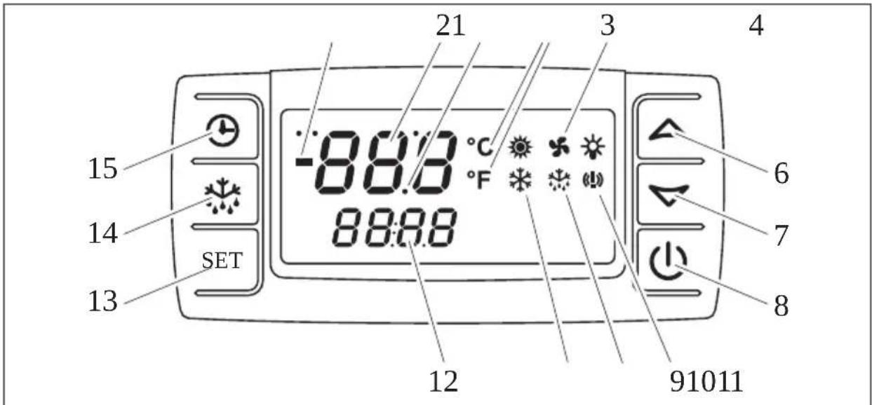
5.1 Control unit
All functions of the cooling system can be operated with the control unit. All relevant values and settings can be seen on the integrated display.
5
Figure 1: Control unit overview
The following functions are controlled with the buttons:
| Item Button Function description |
| 6 – Increases the value |
| 7 – Reduces the value |
| 8 – Switches the system on and off |
| 13 – Changes the target temperature– Confirms the set value |
| 14 – Starts manual defrosting |
| 15 – Displays the stored operating hours |
The display indicates the system status.

NOTE
The symbols and are displayed when the system is switched on, but have no function.
| Item | Symbol | Description | Function description |
| 1 | - | Minus sign - Display of a temperature value below 0 °C | |
| 2 Temperature [67X4] | Display of the current temperature (with a minus sign when combined with a temperature below 0 °C) - Displays additional information: SEr: Maintenance due | ||
| 3 | • | Decimal point - Displayed when decimal temperatures are displayed - Displayed when the cooling system is switched off | |
| 4 | [22T4] | Unit of measurement temperature | - °C: Display in degrees Celsius - °F: Display in degrees Fahrenheit |
5 Blowe  | splayed when the evaporator blower is on - Flashes if the activation of the blower is delayed - Flashes in heating mode | ||
| 9 Alarm | Displayed when there is a temperature alarm (see chapter “Fault messages” on page 21) | ||
| 10 |  | Defrosting | - Displayed in defrosting mode - Flashes during the drip period |
| 11 |  | Compressor - Displayed when the compressor is operating - Flashes in heating mode | |
| 12 |  | Information | - Displays the target temperature (with a minus sign when combined with a temperature below 0 °C) - Displays additional information: SEt: The target temperature can be set |
5.2 Switching on the cooling system

CAUTION!
Make sure that the 220 V mains connection cable of the standby cooling (additional equipment) is not connected!

NOTICE!
The cooling system remains activated when the vehicle ignition is switched off and the ignition key is removed.
▶Switch on the ignition.
▶ Start the engine.
▶Turn off the automatic start/stop system if present.
Refer to the operating manual for your vehicle for information on the use and function of the automatic start/stop system.
▶ After the loading indicator lamp of your vehicle has gone out, press ⏻.
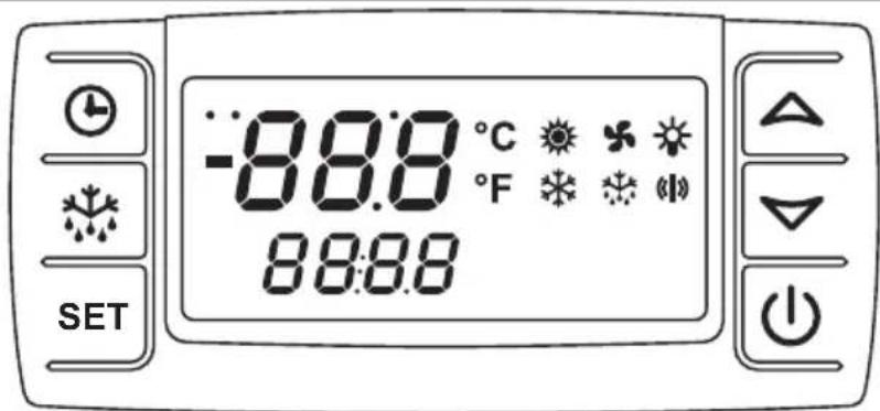
Figure 2: Switching on the cooling system, control test
√ Before switching on the cooling system, the control unit performs a check to ensure that the system is working properly. All symbols are indicated on the display for a few seconds.
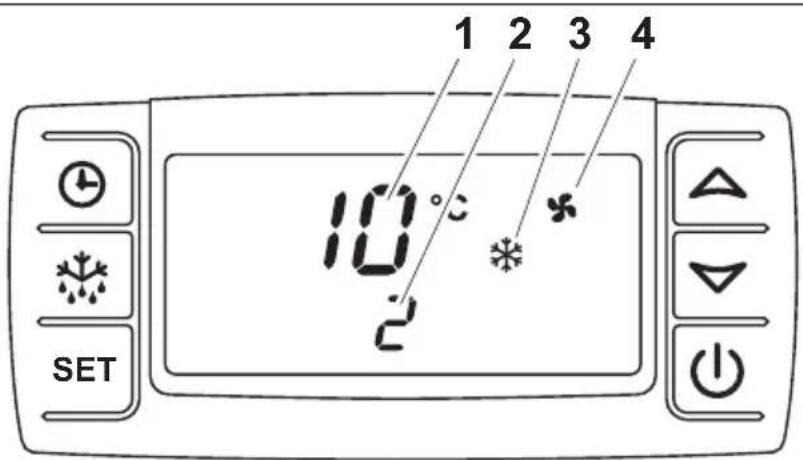
Figure 3: Switching on the cooling system, compressor
√ The display then shows the current loading area temperature (1) and the target temperature (2), and the cooling system is switched on as required, which is recognisable by the display of the symbols ✦ (3) and ✦ (4) on the display.

NOTE
With a loading area temperature above +15 °C, initially only the symbol is displayed.
After a delay, the evaporator blower is switched on, which is recognisable by the display of the symbol on the display.
5.3 Switching off the cooling system

CAUTION!
The cooling system should never be switched off during the defrosting process. Disconnect the mains cable from the mains supply during cooling when parked. Switching off the cooling system has no effect on the last target value set as this is saved automatically when changes are made.
The cooling system should only be switched off if it is not to be used for a longer period.
▶Press the button.
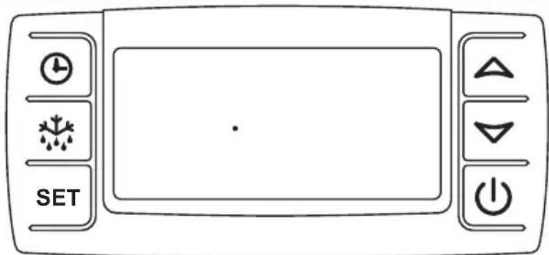
Figure 4: Switching off the cooling system
√"oFF" is displayed on the display for a few seconds.
√The display shows a dot.

NOTICE!
The cooling system must also be switched on for a few minutes every week (during all seasons) when it is not in use. The inspection and maintenance intervals must be adhered to in order to ensure that the system functions remain in perfect condition.
5.4 Locking and unlocking the keypad
The keypad can be locked to prevent any unintentional input with the keys. The keypad needs to be unlocked before any settings can be made using the keys.
▶Press the and buttons simultaneously for three seconds.
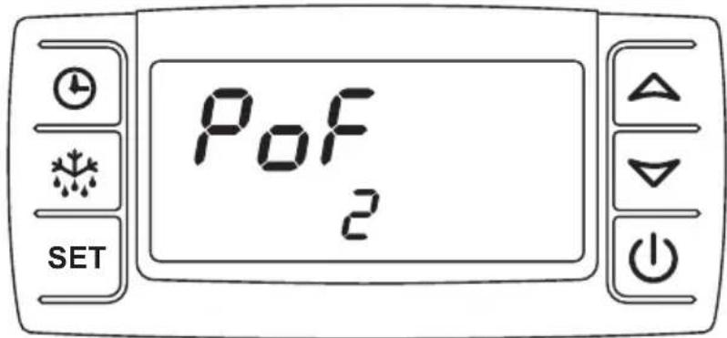
Figure 5: Keypad locked
√The message "PoF" is shown on the display.
√The keypad is locked.

NOTE
After the keypad is locked, the target value of the loading area temperature cannot be changed. Locking of the keypad is indicated by the message "PoF".
▶Press the and buttons simultaneously for three seconds.
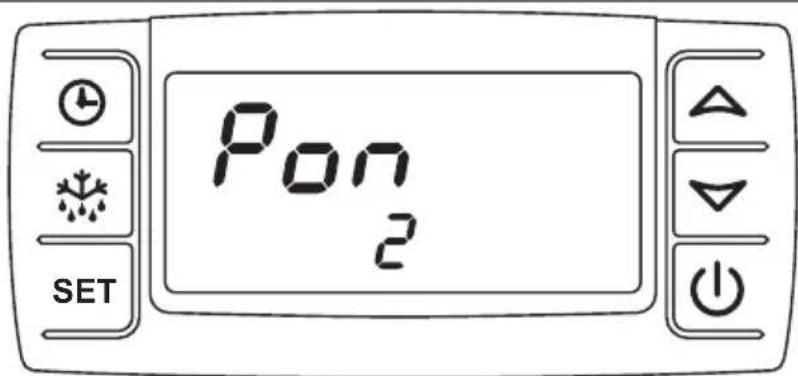
Figure 6: Keypad unlocked
√The message "Pon" is briefly shown on the display.
√The keypad is unlocked.
5.5 Controlling the loading area temperature
Reading off the actual and target temperature value
After the cooling system has been switched on, the display shows the loading area temperature (1) and the target temperature (2).
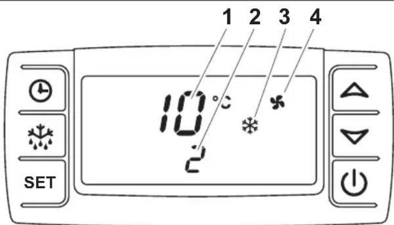
Figure 7: Temperature indication
Item Symbol Meaning
| 1 | 10 | The display indicates the current loading area temperature in °C. |
| 2 | 2 | The display indicates the target temperature in °C. |
| 3 The cooling system starts. | ||
| 4 The evaporator blowers run. | ||

NOTE
The evaporator blower switches on or off depending on the condition of the system.
Changing the target temperature in the loading area
▶Hold down the SET on for 2 seconds.
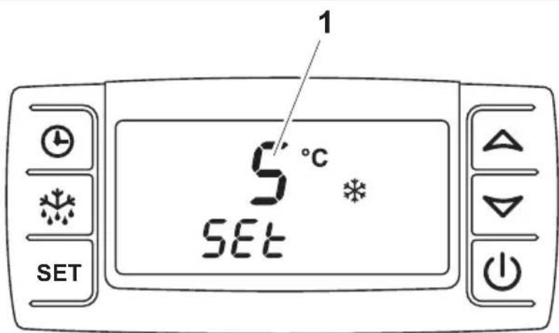
Figure 8: Changing the target temperature
√ The target temperature (1) appears on the display and the °C symbol flashes.

NOTE
If no button is pressed for 10 seconds, the control unit switches back to displaying the loading area temperature and the target temperature is not changed.
▶Within 15 seconds, change the target temperature in 1 °C steps using buttons △ and ▽
The target temperature can be set depending on the system:
System type Temperature range for the cooling area
Cooling unit for chilled goods: Between max. +40 °C and min. +0 °C
Deep freeze unit: Between max. +40 °C and min. -20 °C
Loading area temperature control:
Between max. +12 °C and min. +0 °C
▶Briefly press the SETton.
√The set temperature is saved and applied as the desired target temperature for the cooling area.

NOTE
The target temperature must be set to correspond to the storage temperature for foods (see chapter "Storing fresh food" on page 25).
5.6 Defrosting the cooling system
When the cooling area temperature drops, condensation forms. This condensation freezes on the surface of the evaporator. To obtain full cooling capacity, this ice needs to be removed. This is accomplished with a defrost cycle. If the cooling capacity drops, this is a certain sign that defrosting is necessary.

NOTICE!
The cooling system should never be switched off during manual or automatic defrosting. In the event of frequent interruptions (switching off the cooling system before automatic defrosting, e.g. loading and unloading), it may be necessary to start defrosting manually (see chapter “Manual defrosting” on page 16). Otherwise, the evaporator surface may freeze and the cooling capacity of the plant will be severely limited.

NOTE
The condensation is drained off through the vehicle's drainage line. A puddle may form under the vehicle when it is at a standstill. The drainage hose should be kept clear at all times.
Your cooling system is equipped with one of two defrosting mechanisms:
• Air circulation defrosting:
Only the evaporator blower, assisted by the ambient air, is used to defrost the evaporator.

NOTE
Extended periods of operation of the cooling system without external supply of heat can result in longer defrosting phases. This is not a defect. After a period of 10 minutes, the defrost cycle is terminated automatically.
• Hot gas defrosting: (additional equipment)
Heated refrigerant is used to defrost the evaporator.
Automatic defrosting
An electronic controller starts this process after every complete operating hour.

NOTE
When transporting or storing moist goods, we recommend using manual defrosting more often (see chapter "Manual defrosting" on page 16).
During the defrost cycle, the upper line of the display shows "deF". The bottom line of the display shows the target temperature. The following indicators appear on the display:
Air circulation defrosting Hot gas defrosting
| Symbol is visible Symbol is visible / flashes during the drip period | |
| Symbol not visible Symbol is visible | |
| Symbol is visible Symbol not visible/ flashes during the drip period |
After the defrosting process, the system switches back to cooling automatically. This process can also be seen on the display:
| Symbol not visible | |
| Symbol is visible | |
| Symbol flashes, activation of the blower is delayed after defrosting. After activation, the symbol is visible |
Manual defrosting
The manual defrosting process can be started via the control display as follows:
▶Press the button for at least 2 seconds.
√The defrosting process starts as described in chapter "Automatic defrosting" on page 16.
5.7 Managing measured temperature values

NOTE
The control unit stores the measured maximum and minimum temperatures. This gives you information about the storage conditions of the food in the loading area.
Displaying the measured maximum temperature
▶Press the button.
√On the display, Hi is briefly displayed, followed by the measured and stored temperature.
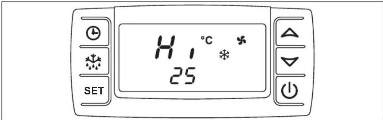
Figure 9: Displaying the measured max. temperature
Displaying the measured minimum temperature
▶Press the button.
√ On the display, "Lo" is briefly displayed, followed by the measured and stored temperature.
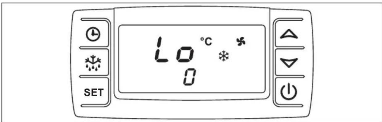
Figure 10: Displaying the measured min. temperature
Deleting the measured temperatures
▶Press the button or the button.
√ On the display, "Hi" or "Lo" is briefly displayed, followed by the measured and stored temperature.
▶Hold down the SET on for longer than 3 seconds.
√"rSt" flashes on the display.
√The current loading area temperature is shown on the display.
5.8 Displaying elapsed operating hours
▶Press the button.
√The display shows the ten thousand operating hours that have already elapsed. The number of operating hours is made up of the top line (steps of ten thousand) and the bottom line (steps of one).

Figure 11: Displaying the elapsed operating hours

NOTE
If "SEr" appears on the display, maintenance must be performed. Initial maintenance should be carried out 100 operating hours after start-up. All other maintenance should be carried out after every 1000 hours of operation. During maintenance, the operating hours are reset.
5.9 Standby cooling with electric motor (additional equipment)

CAUTION!
- The safety cap of the device plug on the vehicle must always be closed if the standby cooling function is not is use.
- Before connecting the cable, the available mains voltage must be checked. It should be fused with at least 16 amps.
- The extension cable should be as short as possible and have a cable cross-section of 3 × 2.5 mm^2 . The length of the extension cable should correspond to the distance between the vehicle and the mains socket. If a cable drum is used for the connection for standby cooling, it should be rolled out fully. Otherwise, the cable becomes very hot and a cable fire can be the result.

NOTE
Periods of low voltage and strong power fluctuations can lead to malfunction.
Switching on the standby cooling
The standby cooling may only be operated under the following conditions:
- The vehicle must be on even ground so that the condensation can drain away.
- The vehicle engine must be switched off and the ignition key removed.
• All loading area doors must be securely shut.

CAUTION!
- Before you start the vehicle again, you must disconnect the mains cable from the socket on the vehicle.
- The 230 V connection of the standby cooling may only be operated with a fault current protected switch with a nominal current of 30 mA and an earthed, splash water-protected mains socket.

NOTE
Observe the following guidelines for proper operation of the standby cooling:
- The car should be parked in the shade during operation of the standby cooling.
- The user is responsible for securing the vehicle during operation of the standby cooling!
- Prior to loading, cool the loading area for approx. 20 – 30 minutes.
- Open the loading area doors just a bit to reduce the entry of moist air.
- The standby cooling is used to maintain the cooling in the loading area. It is not suitable for long-term storage of foods.
- Third-party equipment with 230 V mains voltage may not be operated on the standby cooling! This may cause damage to the cooling system!
▶Turn off the vehicle engine.
▶Connect the mains cable for parking operation to a fused 230 V socket.
▶Switch on the cooling system (see chapter "Switching on the cooling system" on page 9).

NOTE
- The function of the cooling system and its corresponding operating elements in the interior correspond to the function during cooling when driving as described on the previous pages.
- With standby cooling in which the electric motor is in a seat console, sufficient ventilation must be ensured throughout the operation of the standby cooling.
To this end, fold up the passenger seat during operation of the standby cooling. Refer to the operating manual of your vehicle in regard to this function.
6 Fault messages
Faults in the cooling system are shown on the display.
| Display text Cause Result/measure | ||
| P1 | The room temperature sensor is defective. | The cooling system switches off automatically. Call the service hotline. |
| P2 | The evaporator sensor is defective. | The cooling system continues to run, but the fault remains indicated on the display. Call the service hotline. |
| SErThe (!!) symbol illuminates. | Maintenance is due. The cooling system continues to operate. However, the message continues to be shown on the display. Call the service hotline. During maintenance, the operating hours are reset. | |
| HR | High temperature alarm. The set target temperature was not reached. | Switch off the cooling system. Call the service hotline. |
| LA | Low temperature alarm. The set target temperature was not reached. | Switch off the cooling system. Call the service hotline. |
| Only for standby cooling with an electric motor: An acoustic signal sounds. | A fault has occurred during standby cooling operation. | See chapter “Troubleshooting” on page 22. |
| The (!!) symbol illuminates. | The temperature in the interior of the cooling system has exceeded or fallen below the target temperature. | Call the service hotline and provide a detailed description of the fault. |

NOTE
If "PoF" appears on the display, this only means that the keypad is locked. It needs to be unlocked (see chapter "Locking and unlocking the keypad" on page 12).
7 Troubleshooting
7.1 Troubleshooting when the system breaks down
In the event that the system breaks down completely or partially, first check the fuses on the cooling system. These are located in the vicinity of the battery in the engine compartment. The fuse for the evaporator fans are located in the interior of the rear wall. If the fault cannot be rectified, the cooling system may only be inspected and repaired by an authorised partner (see chapter “Service hotline” on page 27).
Please state the exact circumstances under which the fault occurred and how it became noticeable.
Fault Remedy
The system does not work. Check electrical connections where they are accessible.
The compressor makes a loud noise. Switch off the system and drive to the next service workshop.
The V-belt makes a loud noise. Drive at a low speed to the nearest service workshop.
7.2 Troubleshooting when the standby cooling breaks down (additional equipment)

NOTICE!
A standby cooling break-down could be caused by an undersupply of mains voltage or the use of a cable drum that has not been rolled out. Check this before pressing the RESET button.
If a standby cooling system that is fitted with an electronic motor as a drive unit breaks down, a fault is indicated with an acoustic signal.
There is a control unit with a RESET button in the passenger area. This can be used to restart the cooling system.
▶Pull the standby cooling mains plug out of the socket.
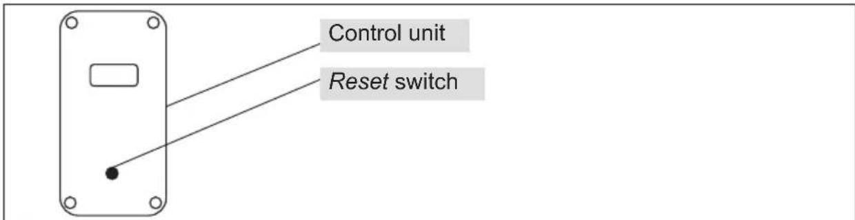
Figure 12: Standby cooling control unit with Reset button
▶ After a short waiting time, press the Reset switch on the control unit into position 1.
▶Plug the standby cooling mains plug into the socket.

NOTE
If the acoustic signal continues to sound, repeat this procedure. If this does not rectify the problem, please contact our service hotline (see chapter "Service hotline" on page 27).
8 Notes on use
8.1 Notes on correct loading
Before you start loading the vehicle, the loading area must be cooled down to the correct temperature level and must be loaded only with properly chilled goods in order to maintain a continuous chain of refrigeration.
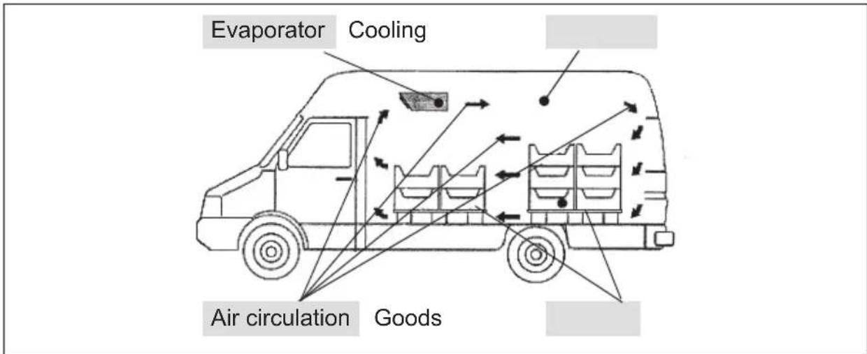
Figure 13: Air circulation in the cooling area
When loading the vehicle, ensure that the cold air leaving the evaporator can circulate freely. The loading area should only be loaded up to approx. 30 cm below the cooling area ceiling. The outlet of the evaporator must be completely free and may not be covered with goods.

NOTE
If the loading area doors are opened frequently, warmth and moisture enter the cooling area. This can cause ice to form on the cooling system, which reduces the cooling capacity. Therefore, open the doors as little and as briefly as possible.
Avoid extended empty runs when the cooling system is activated.
Regularly check proper function of the loading area doors.
Problem-free door seals and functioning door locks contribute to high transport safety.
Regularly check the bodywork in the loading area for damage. Even minor damage can cause your refrigerated items to not be adequately cooled, especially at high ambient temperatures.
8.2 Notes on correct cooling operation

NOTE
The cooling system not only cools but also extracts moisture from the air. The moisture freezes on the surface of the evaporator. This reduces the cooling capacity. The resulting ice must be defrosted at regular intervals to maintain the cooling capacity. The system is defrosted automatically every hour (also see chapter “Defrosting the cooling system” on page 15).
8.3 Storing fresh food
The best way to prevent foods from spoiling is low storage temperatures, as these considerably slow chemical and biological changes to foods. Storing at the temperature stated in the following table enables the foods to retain their original freshness in terms of taste, colour, vitamin and nutrition content.
| Food | Storage temperature |
| Butter and quark | +8 °C ... +10 °C |
| Beef and mutton +4 °C | |
| Veal and pork +4 °C | |
| Poultry and game +4 °C | |
| Trout 0 °C ... +2 °C | |
| Tench and carp | 0 °C ... +2 °C |
| Vegetables +10 °C | |
| Berries +10 °C | |
| Other fruit +10 °C | |
| Fruit cakes and pies | +4 °C ... +6 °C |
| Dry yeast-risen pastries and biscuits | +4 °C ... +6 °C |
| Sorbet and frozen fruit juice | -10 °C |
| Other ice qualities | -15 °C |
| Frozen or deep frozen fish products | -18 °C |
| Other deep frozen food -18 °C | |
| Butter and other deep frozen fatty substances | -10 °C |
| Entrails, eggs without shell, cold cuts and deep-frozen game | -10 °C |
| Deep-frozen meat | -10 °C |
| All other deep-frozen food | -10 °C |

NOTE
This information is only intended as a guideline. The specifications or instructions given by the transport company or recipient of the goods have higher priority.
9 W a r r a n t y

NOTE
Recognition of warranty claims is subject to proof of correct maintenance being carried out.
The warranty refers to a properly and permanently installed cooling system in the vehicle.
The Frigo cooling systems have been built according to the state-of-the-art technology and have been continuously checked to ensure optimum product quality.
If faults in the material or manufacturing do occur, these are rectified in the first 24 months or up to 100,000 km. The start of the warranty depends on
• The date of registration of a new vehicle or
- The handover date of the vehicle equipped with the cooling system to the customer.
This can be done by repairing, overhauling or replacing the affected parts. Call the service hotline in this regard, tel. 02572 879-966.
If it is not possible to have the necessary work performed by an authorised partner in an emergency, it is still necessary to obtain written approval from Dometic WAECO International GmbH.
Failure to observe this invalidates the warranty.
Damage from natural wear, fire, acts of god, tampering by third parties, misuse, inappropriate operation, improper handling and accidents is not covered by the warranty.
There is no recourse for claims for damages, compensation for loss of earning or incurrence of additional costs.
10 Disposal
If you wish to remove the cooling system from operation permanently, dispose of the components individually in the proper way at your local recycling centre.
11 Service hotline
Dear customer,
If you should have any problems with your Frigo cooling system, please contact our service hotline so that we can help you find an authorised workshop in your area.
• Tel.: +49 (0) 2572 879-966
• Fax: +49 (0) 2572 879-967
Vorwort
4 Description technique
4.1 Fonctionnement
Figura 8: Modificar la temperatura nominal
Figur 5: Tastatur spærret
√På displayet vises meldingen „PoF“.
Figur 6: Tastatur frigivet
Figur 8: AEndring af den nominelle temperatur
√ På displayet vises den nominelle temperatur (1), og symbolet °C blinker.

BEMÆRK
Bild 2: Slå på kylanläggning, kontrolltest
Figur 8: Endre innstilt temperatur
dometic.com/sales-offices