PerfectCharge DC 20 - Battery charger DOMETIC - Free user manual and instructions
Find the device manual for free PerfectCharge DC 20 DOMETIC in PDF.

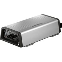
| Product type | Charge transformer (DC/DC converter) for 12V battery |
| Reference | PerfectCharge DC 20 (item no. 9600000096) |
| Dimensions (L x W x H) | 160 x 115 x 70 mm |
| Weight | 1.2 kg |
| Rated input voltage | 12 V== (range 8 V – 16 V) |
| Output voltage | 14.2 V ± 0.1 V |
| Maximum output current | 20 A |
| Maximum efficiency | 87% |
| Protections | Against short circuits, overloads, reverse polarity (by external fuse), overheating (automatic shutdown with fan) |
| Operating temperature | -20°C to +50°C |
| LED display | Power On (green), Battery Low (yellow), Overload (red) |
| Intended use | Charging lead-acid batteries (acid, gel, AGM) and powering 12V devices, installation in camper vans, boats, commercial vehicles |
| Mounting | Horizontal or vertical, 5 cm clearance around, dry and ventilated location |
| Startup | By main switch, ignition contact (terminal 15), or external switch |
| Maintenance | Clean with a damp cloth; do not immerse, do not use abrasive cleaners |
| Warranty | Legal warranty; attach invoice and defect description |
Frequently Asked Questions - PerfectCharge DC 20 DOMETIC
User questions about PerfectCharge DC 20 DOMETIC
0 question about this device. Answer the ones you know or ask your own.
Ask a new question about this device
Download the instructions for your Battery charger in PDF format for free! Find your manual PerfectCharge DC 20 - DOMETIC and take your electronic device back in hand. On this page are published all the documents necessary for the use of your device. PerfectCharge DC 20 by DOMETIC.
USER MANUAL PerfectCharge DC 20 DOMETIC
PerfectCharge DC08, DC20, DC40, DC40 eStore
PerfectPower DCDC10, DCDC20, DCDC40
EN Charger and voltage converter
Installation and Operating Manual.....5
natural_image
Pure electrical circuit lines without any symbolsB
natural_image
Pure electrical circuit lines without any symbolsPlease read this instruction manual carefully before installation and first use, and store it in a safe place. If you pass on the product to another person, hand over this instruction manual along with it.
Contents
1 Explanation of symbols....6
2 General safety instructions....6
3 Scope of delivery ..... 11
4 Proper use .... 11
5 Technical description ..... 12
6 Mounting the converter....13
7 Connecting the converter .....14
8 Using the converter....16
9 Cleaning and caring for the converter .....17
10 Guarantee....17
11 Disposal....17
12 Technical data....18
1 Explanation of symbols

DANGER!
Safety instruction: Failure to observe this instruction will cause fatal or serious injury.

WARNING!
Safety instruction: Failure to observe this instruction can cause fatal or serious injury.

CAUTION!
Safety instruction: Failure to observe this instruction can lead to injury.

NOTICE!
Failure to observe this instruction can cause material damage and impair the function of the product.

NOTE
Supplementary information for operating the product.
2 General safety instructions
The manufacturer accepts no liability for damage in the following cases:
- Damage to the product resulting from mechanical influences and excess voltage
• Alterations to the product without express permission from the manufacturer
• Use for purposes other than those described in the operating manual
Note the following basic safety information when using electrical devices to protect against:
- Electric shock
- Fire hazards
- Injury
2.1 General safety

DANGER!
- In the event of fire, use a fire extinguisher which is suitable for electrical devices.

WARNING!
- Only use the device as intended.
- Ensure that the red and black terminals never come into contact.
- Disconnect the device from the mains:
– Before cleaning and maintenance
- Before changing a fuse
- Before cleaning and maintenance - Before changing a fuse
- If you disassemble the device: - Detach all connections - Make sure that no voltage is present at any of the inputs and outputs
- The device may not be used if the device itself or the connection cable are visibly damaged.
- If this power cable for this device is damaged, it must be replaced by the manufacturer, customer service or a similarly qualified person in order to prevent safety hazards.
- This device may only be repaired by qualified personnel. Inadequate repairs may cause serious hazards.
- People (including children) whose physical, sensory or mental capacities prevent them from using this device safely may not be allowed to operate it without the supervision of a responsible adult.
• Electrical devices are not toys.
Always keep and use the appliance out of the reach of children.
- Children must be supervised to ensure that they do not play with the device.

NOTICE!
- Before start-up, check that the voltage specification on the type plate is the same as that of the power supply.
- Ensure that other objects cannot cause a short circuit at the contacts of the device.
- Store the device in a dry and cool place.
2.2 Safety when installing the device

DANGER!
- Never mount the device anywhere where there is a risk of gas or dust explosion.

CAUTION!
- Ensure that the device is standing firmly.
The device must be set up and fastened in such a way that it cannot tip over or fall down.

NOTICE!
- Do not expose the device to a heat source (such as direct sunlight or heating). Avoid additional heating of the device in this way.
- Set up the device in a dry location where it is protected against splashing water.
2.3 Safety when connecting the device electronically

DANGER! Danger of electrocution
- For installation on boats:
If electrical devices are incorrectly installed on boats, corrosion damage might occur. Have the device installed by a specialist (marine) electrician.
- If you are working on electrical systems, ensure that there is somebody close at hand who can help you in emergencies.

WARNING!
- Always use an adequate fuse in the positive line between the device and the battery.
• Make sure that the lead has a sufficient cross-section.
- Lay the cables so that they cannot be damaged by the doors or the bonnet.
Crushed cables can lead to serious injury.

CAUTION!
- Lay the cables so that they cannot be tripped over or damaged.

NOTICE!
- Use ductwork or cable ducts if it is necessary to lay cables through metal panels or other panels with sharp edges.
- Do not lay the 230 V mains cable and the 12 V DC cable in the same duct.
- Do not lay the cable so that it is loose or heavily kinked.
- Fasten the cables securely.
- Do not pull on the cables.
2.4 Operating the device safely

WARNING!
- Only use the device in closed, well-ventilated rooms.
- Do not operate the device in systems with lead acid batteries. These batteries give off explosive hydrogen gas that can be ignited by sparks on electrical connections.

CAUTION!
- Do not operate the device
- In salty, wet or damp environments
– In the vicinity of corrosive fumes
– In the vicinity of combustible materials -
In areas where there is a danger of explosions.
-
Before starting the device, ensure that the power supply lines are dry.
• Always disconnect the power supply when working on the device. - Please observe that parts of the device may still conduct voltage even if the fuse has blown.
- Do not disconnect any cables when the device is still in use.

NOTICE!
- Make sure the air inlets and outlets of the device are not covered.
- Ensure good ventilation.
2.5 Safety precautions when handling batteries

WARNING!
- Batteries contain aggressive and caustic acids. Avoid battery fluid coming into contact with your body. If your skin does come into contact with battery fluid, wash the part of your body in question thoroughly with water. If you sustain any injuries from acids, contact a doctor immediately.

CAUTION!
- When working on the batteries, do not wear any metal objects such as watches or rings. Lead acid batteries can cause short circuits which can cause serious injuries.
• Danger of explosions!
Never attempt to charge a frozen or defective battery.
Place the battery in a frost-free area and wait until the battery has acclimatised to the ambient temperature. Then start the charging process.
- Wear goggles and protective clothing when you work on batteries. Do not touch your eyes when you are working on the battery.
- Do not smoke and ensure that no sparks can arise in the vicinity of the engine or battery.

NOTICE!
- Only use rechargeable batteries.
- Prevent any metal parts from falling on the battery. This can cause sparks or short-circuit the battery and other electrical parts.
- Make sure the polarity is correct when connecting the battery.
- Follow the instructions of the battery manufacturer and those of the manufacturer of the system or vehicle in which the battery is used.
- If you need to remove the battery, first disconnect the earth connection. Disconnect all connections and all consumers from the battery before removing it.
| 3 | S | c | o | p | e | o | f | d |
Quantity Description
| 1 | C | o | n | v | e | r | t | e | r |
1 Operating manual
4 P r o p e r u s
The transformers convert a --- or 24 V--- supply from a car or boat battery to a stable DC voltage:
• DC08 (ref. no. 9600000095), DC20 (ref. no. 9600000096),
DC40 (ref. no. 9600000097): 12 V--- input voltage to 14.2 V--- output voltage (charge converter)
- DC40 eStore (ref. no. 9600000098): 12 V--- input voltage to 13.8 V--- output voltage (charge converter)
• DCDC10 (ref. no. 9600000084), DCDC20 (ref. no. 9600000086):
12 V--- input voltage to 27.6 V--- output voltage (voltage converter)
• DCDC20 (ref. no. 9600000087), DCDC40 (ref. no. 9600000088):
24 V--- input voltage to 13.8 V--- output voltage (voltage converter)
- DCDC10 (ref. no. 9600000085): 24 V--- input voltage to 27.6 V--- output voltage (voltage converter)
All the converters can also be use to charge lead batteries.

NOTICE!
Never use the device to charge other battery types (such as NiCd or NiMH).
The output voltage of the voltage converter is 13.8 V/27.6 V.
On charge converters, the output voltage follows an IU charging curve to a maximum of 14.2 V (DC40 eStore: 13.8 V). This means the battery is charged more quickly.

NOTICE!
Charge converter: Do not charge for longer than twelve hours.
5 Technical description
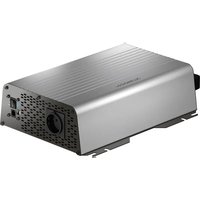
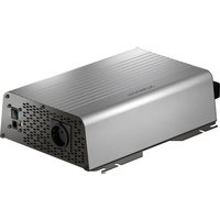
The light weight and compact construction allows the converters to be easily installed in mobile homes, commercial vehicles or motor and sailing vessels.
The transformers convert a 12 V--- or 24 V--- supply from a car or boat battery to a stable 12 V--- or 24 V--- voltage for connecting to equipment.
The isolation of the input and output voltages means the output voltage can be kept stable without interference from the input circuit.
Because the maximum output current is electronically regulated, the charge converters can be used to charge batteries to generate electricity in cars or on boats.
The devices are equipped with protection against shorting and overloading. If the protective function triggers, the device switches off and then switches on again when correctly connected or when the load has been adequately reduced.
5.1 Control elements
| No. in fig. 1, Explanation page 3 |
| 1 Output terminals |
| 2 “Power On” LED: There is voltage at the output terminals on the converter. The converter is ready for use. |
| 3 “Battery Low” LED: The input battery is no longer sufficiently charged. |
| 4 “Overload” LED:- If a consumer is connected: The converter is shorted or overloaded.- If connected as a charger: The converter is in the full current charging phase. |
| 5 Air outlet |
| 6 Main switch |
| 7 Red: Positive cable to input batteryBlack: Negative cable to input battery |
| 8 Connection for switching on with on-board voltage (e.g. ignition or external switch) |
6 M o u n t i n g
6.1 Mounting instructions
If you wish to mount the converter in a fixed position, please observe the following mounting instructions:
- You can mount the device either horizontally or vertically.
-
Do not mount the device
-
In wet or damp environments
– In the vicinity of combustible materials
– In areas where there is a danger of explosions -
The place of installation must be well-ventilated. A ventilation system must be present for installations in small, closed spaces. The minimum clearance around the device must be at least 5 cm (fig. 2, page 3).
- The air intake on the underside or the air outlet on the back of the device must remain clear.
- For ambient temperatures higher than 40 °C (such as in engine or heating compartments, or direct sunlight), the heat from the device under load can lead to the automatic shut-down.
- The installation surface must be level and sufficiently sturdy.

NOTICE!
Before drilling any holes, ensure that no electrical cables or other parts of the vehicle can be damaged by drilling, sawing and filing.
6.2 Mounting the converter
▶Hold the converter against the installation location and mark the fastening points (fig. 3 A, page 3).
▶ Fasten the converter using your chosen method (fig. 3 B, page 3).
7 Connecting the converter
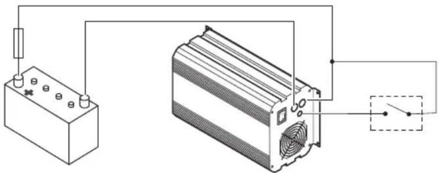
7.1 Connecting the input battery

WARNING!
Do not reverse the polarity. Reverse polarity of the battery connections can cause injury and irreversably damage the device.

NOTICE!
Tighten the nuts or bolts to a torque of 12 – 13 Nm. Loose connections may cause overheating.
▶ Set the main switch (fig. 1 6, page 3) to "0".
▶ Lay the positive cable (red) (fig. 1 7, page 3) from the converter to positive terminal of the battery and connect it.
▶ Lay the negative cable (black) (fig. 1 7, page 3) from the converter to negative terminal of the battery and connect it.
7.2 Connecting the connection cable
You can switch on the device as follows:
• Using the main switch on the device (fig. 1 6, page 3)
• Using the ignition (fig. 5 A, page 4)
Terminal 15: Connected positive terminal
• Using an external switch (fig. 5 B, page 4)
Connecting the converter to be switched on via the main switch
▶Isolate the connecting line so no malfunction can occur.
Connecting the converter to be switched on via the ignition
▶ Connect the connecting line to terminal 15 (connected positive terminal) (fig. 5 A, page 4).
▶ Set the main switch (fig. 1 6, page 3) on the back of the converter to "0" permanently.
Connecting the converter to be switched on via an external switch
▶ Connect the connecting line to an external switch (fig. 5 B, page 4).
▶ Set the main switch (fig. 1 6, page 3) on the back of the converter to "0" permanently.
7.3 Connecting power consuming devices to the converter
▶ Loosen the screw (fig. 4 2, page 4) from the positive terminal (red) (fig. 4 4, page 4).
▶ Push the cable lug (fig. 4 3, page 4) of the positive cable of the power consuming device into the positive terminal (red) (fig. 4 4, page 4) and attach it using the screw (fig. 4 2, page 4) and the spring washer (fig. 4 1, page 4).
▶Connect the negative cable of the power consuming device in the same way to the negative terminal (black) (fig. 4 4, page 4).
8 U s i n g t h e
You can switch on the device as follows, depending on the connection:
• Using the main switch on the device (fig. 1 6, page 3)
• Using the ignition (fig. 5 A, page 4)
Terminal 15: Connected positive terminal
• Using an external switch (fig. 5 B, page 4)
Switching on the converter
▶ Set the main switch (fig. 1 6, page 3) on the back of the converter to "1" ...
... or start the ignition ...
... or push the external switch.
√ The LEDs (fig. 1 3 to 5, page 3) indicate the operating status:
LED Colour Explanation
| Power On Green The device is switched on and there is voltage at the output terminals on the converter. The converter is ready for use. | ||
| Battery Low | Yellow | The input battery is no longer sufficiently charged.➢ Recharge the battery or use a charged battery. |
| Overload | Red | If a consumer is connected:The converter is shorted or overloaded.➢ Eliminate the short circuit or reduce the output load.If connected as a charger:The converter is in the full current charging phase. |

NOTE
The internal fan is operated according to the temperature. It only runs when the temperature is too high. During this time the converter is switched off to prevent overheating.
Switching off the converter
▶ Set the main switch (fig. 1 6, page 3) on the back of the converter to "0" ...
... or switch off the ignition ...
... or push the external switch.
9 Cleaning and caring for the converter

NOTICE! Danger of damaging the device!
Never clean the device under running water or in dish water.
Do not use abrasive cleaning agents or hard objects during cleaning as these can damage the device.
▶Occasionally clean the device with a damp cloth.
10 Guarantee
The statutory warranty period applies. If the product is defective, please contact the manufacturer's branch in your country (see the back of the instruction manual for the addresses) or your retailer.
For repair and guarantee processing, please include the following documents when you send in the device:
• A copy of the receipt with purchasing date
- A reason for the claim or description of the fault
11 Disposal
▶ Place the packaging material in the appropriate recycling waste bins wherever possible.
If you wish to finally dispose of the product, ask your local recycling centre or specialist dealer for details about how to do this in accordance with the applicable disposal regulations.
12 Technical data
| DCDC10 DCDC20 | ||
| Reference no.: 9600000084 9600000086 | ||
| Transformation: | 12 V → 24 V | |
| Rated input voltage: 12 V--- | ||
| Input voltage range: 8 V – 16 V | ||
| Output current: 10 A 20 A | ||
| Output voltage: 27.6 V ± 0.1 V | ||
| Efficiency up to: | 87 % | |
| Interference suppression: | 40 mA | |
| Ambient temperature for operation: | -20 °C to +50 °C | |
| Dimensions W x D x H: | 140 x 115 x 70 mm | 240 x 115 x 70 mm |
| Weight: | 1.0 kg | 1.9 kg |
| DCDC20 | DCDC40 | ||
| Reference no.: 9600000087 9600000088 | |||
| Transformation: | 24 V → 12 V | ||
| Rated input voltage: | 24 V--- | ||
| Input voltage range: | 20 V - 32 V | ||
| Output current: | 20 A | 40 A | |
| Output voltage: 13.8 V ± 0.1 V | |||
| Efficiency up to: | 87 % | ||
| Interference suppression: | 20 mA | ||
| Ambient temperature for operation: | -20 °C to +50 °C | ||
| Dimensions W x D x H: | 140 x 115 x 70 mm | 240 x 115 x 70 mm | |
| Weight: | 1.0 kg | 1.9 kg | |
| DC08 DC20 DC40 | |||
| Reference no.: 9600000095 9600000096 9600000097 | |||
| Transformation: | 12 V → 12 V | ||
| Rated input voltage: 12 V--- | |||
| Input voltage range: 8 V – 16 V | |||
| Output current: 8 A 20 A 40 A | |||
| Output voltage: 14.2 V ± 0.1 V | |||
| Efficiency up to: 87 % | |||
| Interference suppression: | 20 mA | ||
| Ambient temperature for operation: | -20 °C to +50 °C | ||
| Dimensions W x D x H: | 100 x 115 x 70 mm | 160 x 115 x 70 mm | 270 x 115 x 70 mm |
| Weight: | 0.75 kg | 1.2 kg | 2.1 kg |
| DCDC10 | DC40 eStore | |
| Reference no.: | 9600000085 | 9600000098 |
| Transformation: | 24 V → 24 V | 12 V → 12 V |
| Rated input voltage: | 24 V--- | 12 V--- |
| Input voltage range: | 20 V – 32 V | 8 V – 16 V |
| Output current: | 10 A | 40 A |
| Output voltage: 27.6 V ± 0.1 V | 13.8 V ± 0.1 V | |
| Efficiency up to: | 87 % | 87 % |
| Interference suppression: | 40 mA | 20 mA |
| Ambient temperature for operation: | -20 °C to +50 °C –20 °C to +50 °C | |
| Dimensions W x D x H: | 140 x 115 x 70 mm | 270 x 115 x 70 mm |
| Weight: | 1.0 kg | 2,1 kg |
Certification


5 Description technique
Dometic Australia Pty. Ltd.
1 John Duncan Court
Varsity Lakes QLD 4227
1800 212121
+61 7 55076001
Mail: sales@dometic-waeco.com.au
AUSTRIA
Dometic Austria GmbH
Neudorferstraße 108
A-2353 Guntramsdorf
+43 2236 908070
+43 2236 90807060
Mail: info@dometic.at
BENELUX
Dometic Branch Office Belgium
Zincstraat 3
B-1500 Halle
+32 2 3598040
+32 2 3598050
Mail: info@dometic.be
BRAZIL
Dometic DO Brasil LTDA
Avenida Paulista 1754, conj. 111
SP 01310-920 Sao Paulo
+551132513352
+551132513362
Dometic Group Asia Pacific
Suites 2207-11 · 22/F · Tower 1
The Gateway · 25 Canton Road,
Tsim Sha Tsui · Kowloon
+852 2 4611386
+852 2 4665553
Mail: info@waeco.com.hk
HUNGARY
Dometic Zrt. Sales Office
Kerékgyártó u. 5.
H-1147 Budapest
+3614684400
+3614684401
Dometic Italy S.r.l.
Via Virgilio, 3
I-47122 Forlì (FC)
+39 0543 754901
+39 0543 754983
Mail: vendite@dometic.it
JAPAN
Dometic KK
Maekawa-Shibaura, Bldg. 2
2-13-9 Shibaura Minato-ku
Tokyo 108-0023
+81 3 5445 3333
+81354453339
Mail: info@dometic.jp
MEXICO
Circuito Médicos No. 6 Local 1
Colonia Ciudad Satélite
CP 53100 Naucalpan de Juárez
Estado de México
+52 55 5374 4108
+52 55 5393 4683
Mail: info@dometic.com.mx
NETHERLANDS
Dometic Benelux B.V.
Ecustraat 3
NL-4879 NP Etten-Leur
+31 76 5029000
+31 76 5029019
Mail: info@dometic.nl
NEW ZEALAND
Dometic New Zealand Ltd.
Unite E, The Gate
373 Neilson Street
Penrose 1, Auckland
+6496221490
+6496221573
Mail: customerservices@dometic.co.nz
NORWAY
Dometic Norway AS
∅sterøyveien 46
N-3232 Sandefjord
+47 33428450
+47 33428459
Mail: firmapost@dometic.no
POLAND
Dometic Poland Sp. z o.o.
Ul. Puławska 435A
PL-02-801 Warszawa
+48 22 414 3200
+48 22 414 3201
Mail: info@dometic.pl
PORTUGAL
Dometic Spain, S.L.
Komsomolskaya square 6-1
RU-107140 Moscow
+7 495 780 79 39
+7 495 916 56 53
Mail: info@dometic.ru
SINGAPORE
Dometic Pte Ltd
18 Boon Lay Way 06-140 Trade Hub 21
Singapore 609966
+65 6795 3177
+65 6862 6620
Mail: dometic@dometic.com.sg
SLOVAKIA
Dometic Slovakia s.r.o. Sales Office Bratislava
Nádražná 34/A
900 28 Ivánka pri Dunaji
/ +421 2 45 529 680
Mail: bratislava@dometic.com
SOUTH AFRICA
Dometic (Pty) Ltd.
Regional Office
South Africa & Sub-Saharan Africa
2 Avalon Road
West Lake View Ext 11
Modderfontein 1645
Johannesburg
+27114504978
+27114504976
Mail: info@dometic.co.za
SPAIN
Dometic Spain S.L.
Avda. Sierra del Guadarrama, 16
E-28691 Villanueva de la Cañada
Madrid
+34 902 111 042
+34 900 100 245
Mail: info@dometic.es
SWEDEN
Dometic Scandinavia AB
Gustaf Melins gata 7
Dometic Switzerland AG
Riedackerstrasse 7a
CH-8153 Rümlang
+41 44 8187171
+41 44 8187191
Mail: info@dometic.ch
UNITED ARAB EMIRATES
Dometic Middle East FZCO
P.O.Box17860
S-D 6, Jebel Ali Freezone
Dubai
+97148833858
+97148833868
Mail: info@dometic.ae
UNITED KINGDOM
Dometic UK Ltd.
Dometic House, The Brewery
Blandford St. Mary
Dorset DT11 9LS
+44 344 626 0133
+44 344 626 0143
Mail: customerservices@dometic.co.uk
USA
Dometic RV Division
1120 North Main Street
Elkhart, IN 46515
+1574-264-2131