
PWA-TD1 - Server SONY - Free user manual and instructions
Find the device manual for free PWA-TD1 SONY in PDF.

| Product Type | Video Acquisition and Storage Server |
| Brand | Sony |
| Model | PWA-TD1 (server module for PWS-300TD2) |
| Category | Server |
| Main Functions | Video acquisition (SDI inputs), quality control, storage on internal disks and ODA cartridges, automated workflow, web control application, integration with management software |
| System Configurations | 2 inputs/2 outputs, 3 inputs/1 output, 4 inputs (depending on codec and CODEC card) |
| SDI Connectors | HD-SDI (BNC): 4 inputs/outputs on XAVC 4K/HD card, 4 per SSTP CODEC card (2 cards) |
| Remote Connectors | RJ-45 (3) for RS422 (Sony VTR 9-pin protocol) with provided adapter |
| USB Connectors | USB 3.0 (2) for playback units, USB power supported |
| Network Connector | 10 Gigabit Ethernet (SFP+ or RJ-45 depending on card) |
| Sync Reference | REF IN (BNC): HD tri-level sync or SD black burst/composite |
| RAID Configurations | 2D+1P, 3D+1P, 5D+1P (12 hard drives total) |
| Supported Video Codecs | SStP (via option PWSL-TD11/01), XAVC-I, MPEG-HD, IMX, Uncompressed SD (via option PWSL-TD12/01) |
| Web Application | Graphical interface via browser (HTTPS): https:// or https://pws-300- |
| Default Credentials | User: admin, Password: tds |
| Recommended Client PC | CPU Core i5 3 GHz, 4 GB RAM, Windows 7/8/8.1 Pro or Mac OS X 10.8/10.9, Chrome 40+ browser |
| Supplied Accessories | RJ-45 to D-sub adapter cable (3 pieces) |
| Security | Passwords to configure, SSL certificate to install, UPS recommended, close browser after use |
| Maintenance | Check disk indicators (amber blinking = rebuilding), replace disk if SYSTEM red |
Frequently Asked Questions - PWA-TD1 SONY
C:\Users\Public\Documents), convert disks to GPT, format with an allocation unit size of 64k, then restart.https://:8443/tds or https://pws-300-:8443/tds . Log in with username admin and password tds.User questions about PWA-TD1 SONY
0 question about this device. Answer the ones you know or ask your own.
Ask a new question about this device
Download the instructions for your Server in PDF format for free! Find your manual PWA-TD1 - SONY and take your electronic device back in hand. On this page are published all the documents necessary for the use of your device. PWA-TD1 by SONY.
USER MANUAL PWA-TD1 SONY
TAPE DIGITIZE APPLICATION
PWA-TD1
SSTP DOUBLE SPEED OPTION
PWSL-TD11/01
EXTENDED CODEC OPTION
PWSL-TD12/01
INSTALLATION GUIDE
Japanese/English/French/German/Italian/Spanish/Chinese/Korean
1st Edition
目次
概要 3
システム構成例 4
RAID 構成の選択.....10
各部の名称と働き 14
準備 15
初期設定....15
Web メニューの表示....15
システム設定....15
証明書をインストールする....15
①USB 3.0 端子
Intel Ether Converged Network Adapter X520
SFP+ (1)
- Intel Ethernet SFP+ SR Optic (E10GSFPSR)
- Intel Ethernet SFP+ LR Optic (E10GSFPLR)
Intel Ether Converged Network Adapter X540
RJ-45 (1)
10GBASE-T
付属品
Name and Function of Parts.... 31
Setting Up 32
Initial Settings.... 32
Displaying the Web Application 32
System Settings 32
Installing Certificates 32
Library Licenses 33
Usage Precautions.... 34
Specifications.... 34
For safety, please read the precautions described in the PWS-300 Operation Guide.
Overview
The PWS-300TD2 (PWS-300 + PWA-TD1) is a system for digitizing VTR material to create clips and for storing clips on cartridges in an Optical Disc Archive System. It features the following functions.
Ingest
The unit creates high-resolution video and proxy video files from input SDI signals from one or more VTRs and stores the ingested clips on internal HDDs. It can also control VTR devices remotely using an RS422 interface.
Video quality checking
The video quality of ingested clips can be checked automatically. The video can also be checked visually by an operator in the web application screen or on an external monitor.
Clip storage
High-resolution clips can be transferred and stored on cartridges or on a network server.
Workflows
A series of tasks, from ingesting through to transfer of clips, can be executed in a single operation using workflows. A manager can defines the workflow tasks to execute and assign an operator to execute the tasks in a work order, and the operator then executes the tasks according to the work order.
Web application
Control and configuration of the unit is performed using a graphical interface displayed in a web browser on a client PC.
Integration with management software
The properties of clips stored on cartridges and proxy video files can be exported and managed using other software.
Codec option
SStP high-speed ingest is supported by the addition of the PWSL-TD11/01 SStP Double Speed Option.
XAVC-I, MPEG-HD, IMX, and Uncompressed SD files can be generated by the addition of the PWSL-TD12/01 Extended Codec Option.
For details about adding the codec option, consult your Sony dealer or service representative.
System Configuration Examples
Connect VTRs and external monitors to the SDI connectors of the unit, and drive units to the USB 3.0 connectors on the rear panel. You can select a 2-input/2-output, 3-input/1-output, or 4-input system configuration by configuring SDI settings in the web application. Only the 2-input/2-output configuration can be set for the SStP codec. Any system configuration can be selected for the XAVC-I, MPEG-HD, IMX, and Uncompressed SD codecs.
Up to two drive units can be connected.
2 inputs/2 outputs
Connect two VTRs and two external monitors to the SDI connectors. You can use this configuration to digitize video from two VTRs in parallel.
The SStP (Single/DBL) codec uses the SDI connectors of two SSTP CODEC CARDs. The XAVC-I, MPEG-HD, IMX, and Uncompressed SD codecs use the SDI connectors on the XAVC 4K/HD CODEC CARD.
Notes
- If multiple VTRs are connected, make sure that all VTRs are synchronized (±1H).
- Set the EE/PB setting of the VTR to PB.

flowchart
graph TD
    A["Operator Operator Manager"] --> B["Gigabit Ethernet"]
    B --> C["External monitor"]
    C --> D["HD/SD SDI"]
    C --> E["HD/SD SDI"]
    C --> F["HD/SD SDI"]
    C --> G["HD/SD SDI"]
    C --> H["HD/SD SDI"]
    C --> I["HD/SD SDI"]
    C --> J["HD/SD SDI"]
    C --> K["HD/SD SDI"]
    C --> L["HD/SD SDI"]
    C --> M["HD/SD SDI"]
    C --> N["HD/SD SDI"]
    C --> O["HD/SD SDI"]
    C --> P["HD/SD SDI"]
    C --> Q["HD/SD SDI"]
    C --> R["HD/SD SDI"]
    C --> S["HD/SD SDI"]
    C --> T["HD/SD SDI"]
    C --> U["HD/SD SDI"]
    C --> V["HD/SD SDI"]
    C --> W["HD/SD SDI"]
    C --> X["HD/SD SDI"]
    C --> Y["HD/SD SDI"]
    C --> Z["HD/SD SDI"]
    C --> AA["HD/SD SDI"]
    C --> AB["HD/SD SDI"]
    C --> AC["HD/SD SDI"]
    C --> AD["HD/SD SDI"]
    C --> AE["HD/SD SDI"]
    C --> AF["HD/SD SDI"]
    C --> AG["HD/SD SDI"]
    C --> AH["HD/SD SDI"]
    C --> AI["HD/SD SDI"]
    C --> AJ["HD/SD SDI"]
    C --> AK["HD/SD SDI"]
    C --> AL["HD/SD SDI"]
    C --> AM["HD/SD SDI"]
    C --> AN["HD/SD SDI"]
    C --> AO["HD/SD SDI"]
    C --> AP["HD/SD SDI"]
    C --> AQ["HD/SD SDI"]
    C --> AR["HD/SD SDI"]
    C --> AS["HD/SD SDI"]
    C --> AT["HD/SD SDI"]
    C --> AU["HD/SD SDI"]
    C --> AV["HD/SD SDI"]
    C --> AW["HD/SD SDI"]
    C --> AX["HD/SD SDI"]
    C --> AY["HD/SD SDI"]
    C --> AZ["HD/SD SDI"]
    C --> BA["HD/SD SDI"]
    C --> BB["HD/SD SDI"]
    C --> BC["HD/SD SDI"]
    C --> BD["HD/SD SDI"]
    C --> BE["HD/SD SDI"]
    C --> BF["HD/SD SDI"]
    C --> BG["HD/SD SDI"]
    C --> BH["HD/SD SDI"]
    C --> BI["HD/SD SDI"]
    C --> BJ["HD/SD SDI"]
    C --> BK["HD/SD SDI"]
    C --> BL["HD/SD SDI"]
    C --> BM["HD/SD SDI"]
    C --> BN["HD/SD SDI"]
    C --> BO["HD/SD SDI"]
    C --> BP["HD/SD SDI"]
    C --> BQ["HD/SD SDI"]
    C --> BR["HD/SD SDI"]
    C --> BS["HD/SD SDI"]
    C --> BT["HD/SD SDI"]
    C --> BU["HD/SD SDI"]
    C --> BV["HD/SD SDI"]
    C --> BW["HD/SD SDI"]
    C --> BX["HD/SD SDI"]
    C --> BY["HD/SD SDI"]
    C --> BZ["HD/SD SDI"]
    C --> CA["HD/SD SDI"]
    C --> CB["HD/SD SDI"]
    C --> CC["HD/SD SDI"]
    C --> CD["HD/SD SDI"]
    C --> CE["HD/SD SDI"]
    C --> CF["HD/SD SDI"]
    C --> CG["HD/SD SDI"]
    C --> CH["HD/SD SDI"]
    C --> CI["HD/SD SDI"]
    C --> CJ["HD/SD SDI"]
    C --> CK["HD/SD SDI"]
    C --> CR["HD/SD SDI"]
    C --> CS["HD/SD SDI"]
    C --> CT["HD/SD SDI"]
    C --> CU["HD/SD SDI"]
    C --> CV["HD/SD SDI"]
    C --> CW["HD/SD SDI"]
    C --> CX["HD/SD SDI"]
    C --> CY["HD/SD SDI"]
    C --> CZ["HD/SD SDI"]
    C --> DA["HD/SD SDI"]
    C --> DB["HD/SD SDI"]
    C --> DC["HD/SD SDI"]
    C --> DD["HD/SD SDI"]
    C --> DE["HD/SD SDI"]
    C --> DF["HD/SD SDI"]
    C --> DG["HD/SD SDI"]
    C --> DH["HD/SD SDI"]
    C --> DI["HD/SD SDI"]
    C --> DJ["HD/SD SDI"]
    C --> DK["HD/SD SDI"]
    C --> DL["HD/SD SDI"]
    C --> DN["HD/SD SDI"]
    C --> DO["HD/SD SDI"]
Connections (SStP Single)
flowchart
graph LR
    A["External monitor 1"] -->|HD/SD SDI HD/SD SDI| B["Internal Unit"]
    C["VTR1"] -->|RS422 RS422| B
    D["VTR2"] --> B
    B --> E["External monitor 2"]
    B --> F["Computer monitor"]
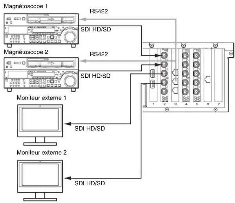
Connect the VTRs to the SDI 1 connector, and the external monitors to the SDI 2 connectors, on the two SSTP CODEC CARDs. This configuration uses the REMOTE 1/2 connector.
Connections (SStP DBL)
flowchart
graph LR
    A["External monitor 1"] -->|HD/SD SDI HD/SD SDI| B["Internal Monitor 1"]
    C["VTR1"] -->|RS422 RS422| B
    D["VTR2"] -->|RS422 RS422| B
    B --> E["External monitor 2"]
    E --> F["Computer"]
Connect the VTRs to the SDI 1 and SDI 3 connectors on the SSTP CODEC CARDs using two SDI cables. Connect the external monitors to the SDI 2 connectors. This configuration uses the REMOTE 1/2 connector.
Connections (XAVC-I, MPEG-HD, IMX, Uncompressed SD)
flowchart
graph TD
    A["VTR1"] -->|RS422| B["External monitor 1"]
    C["VTR2"] -->|RS422| D["External monitor 2"]
    B --> E["HD/SD SDI"]
    D --> F["HD/SD SDI"]
    E --> G["Internal device 1"]
    F --> H["Internal device 2"]
Connect VTRs to the SDI 1 and SDI 2 connectors, and external monitors to the SDI 3 and SDI 4 connectors, on the XAVC 4K/HD CODEC CARD. This configuration uses the REMOTE 3/4 connector.
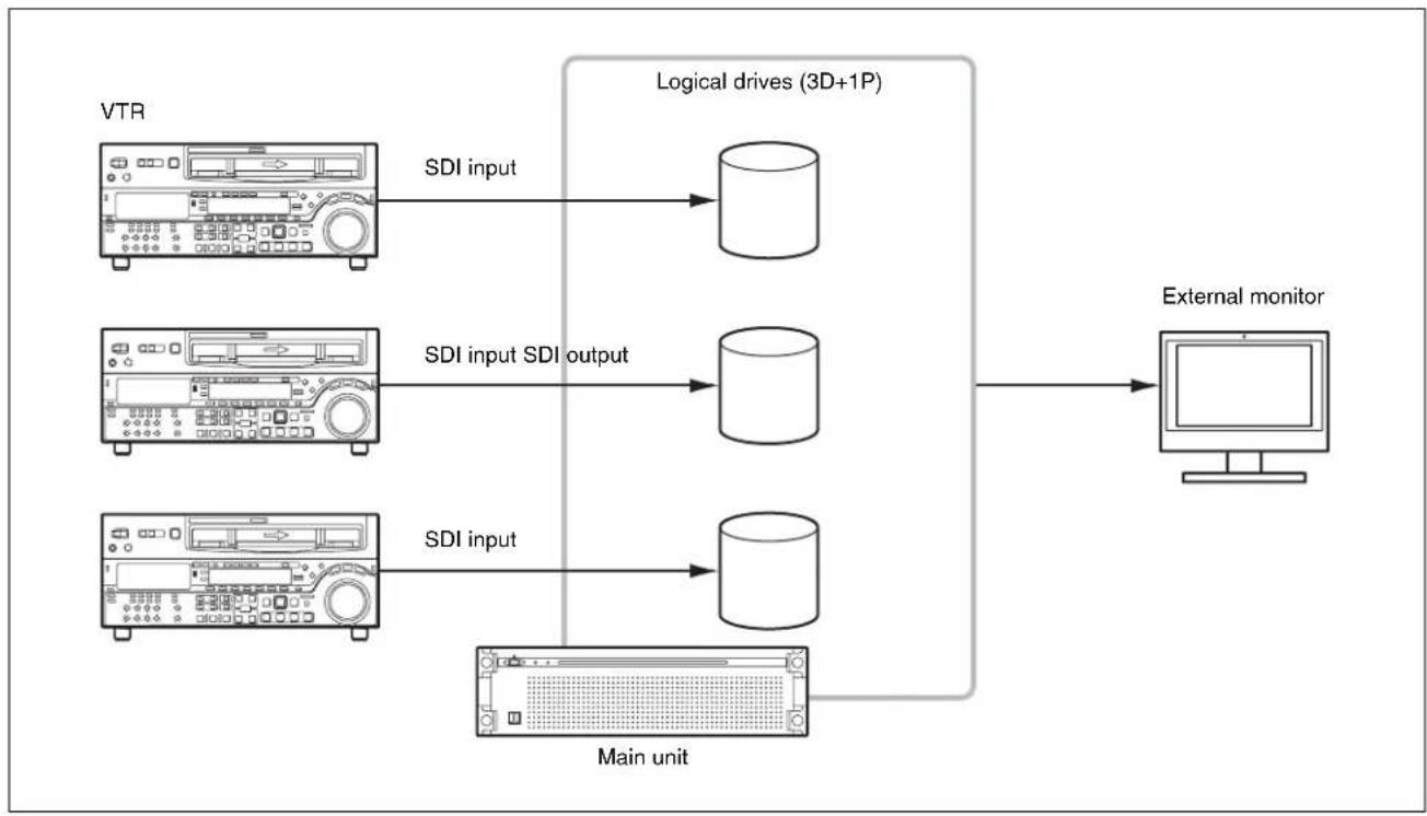
3 inputs/1 output
This configuration can be set for XAVC-I, MPEG-HD, IMX, and Uncompressed SD. Connect VTRs to the SDI 1 to 3 connectors, and an external monitor to the SDI 4 connector, on the XAVC 4K/HD CODEC CARD. The external monitor connected to the SDI 4 connector is used to monitor the high-resolution images of clips.
flowchart
graph TD
    A["Operator Operator Manager"] --> B["Gigabit Ethernet"]
    B --> C["External monitor"]
    C --> D["HD/SD SDI"]
    C --> E["HD/SD SDI"]
    C --> F["HD/SD SDI"]
    C --> G["HD/SD SDI"]
    C --> H["HD/SD SDI"]
    C --> I["HD/SD SDI"]
    C --> J["HD/SD SDI"]
    C --> K["HD/SD SDI"]
    C --> L["HD/SD SDI"]
    C --> M["HD/SD SDI"]
    C --> N["HD/SD SDI"]
    C --> O["HD/SD SDI"]
    C --> P["HD/SD SDI"]
    C --> Q["HD/SD SDI"]
    C --> R["HD/SD SDI"]
    C --> S["HD/SD SDI"]
    C --> T["HD/SD SDI"]
    C --> U["HD/SD SDI"]
    C --> V["HD/SD SDI"]
    C --> W["HD/SD SDI"]
    C --> X["HD/SD SDI"]
    C --> Y["HD/SD SDI"]
    C --> Z["HD/SD SDI"]
    C --> AA["HD/SD SDI"]
    C --> AB["HD/SD SDI"]
    C --> AC["HD/SD SDI"]
    C --> AD["HD/SD SDI"]
    C --> AE["HD/SD SDI"]
    C --> AF["HD/SD SDI"]
    C --> AG["HD/SD SDI"]
    C --> AH["HD/SD SDI"]
    C --> AI["HD/SD SDI"]
    C --> AJ["HD/SD SDI"]
    C --> AK["HD/SD SDI"]
    C --> AL["HD/SD SDI"]
    C --> AM["HD/SD SDI"]
    C --> AN["HD/SD SDI"]
    C --> AO["HD/SD SDI"]
    C --> AP["HD/SD SDI"]
    C --> AQ["HD/SD SDI"]
    C --> AR["HD/SD SDI"]
    C --> AS["HD/SD SDI"]
    C --> AT["HD/SD SDI"]
    C --> AU["HD/SD SDI"]
    C --> AV["HD/SD SDI"]
    C --> AW["HD/SD SDI"]
    C --> AX["HD/SD SDI"]
    C --> AY["HD/SD SDI"]
    C --> AZ["HD/SD SDI"]
    C --> BA["HD/SD SDI"]
    C --> BB["HD/SD SDI"]
    C --> BC["HD/SD SDI"]
    C --> BD["HD/SD SDI"]
    C --> BE["HD/SD SDI"]
    C --> BF["HD/SD SDI"]
    C --> BG["HD/SD SDI"]
    C --> BH["HD/SD SDI"]
    C --> BI["HD/SD SDI"]
    C --> BJ["HD/SD SDI"]
    C --> BK["HD/SD SDI"]
    C --> BL["HD/SD SDI"]
    C --> BM["HD/SD SDI"]
    C --> BN["HD/SD SDI"]
    C --> BO["HD/SD SDI"]
    C --> BP["HD/SD SDI"]
    C --> BQ["HD/SD SDI"]
    C --> BR["HD/SD SDI"]
    C --> BS["HD/SD SDI"]
    C --> BT["HD/SD SDI"]
    C --> BU["HD/SD SDI"]
    C --> BV["HD/SD SDI"]
    C --> BW["HD/SD SDI"]
    C --> BX["HD/SD SDI"]
    C --> BY["HD/SD SDI"]
    C --> BZ["HD/SD SDI"]
    C --> CA["HD/SD SDI"]
    C --> CB["HD/SD SDI"]
    C --> CC["HD/SD SDI"]
    C --> CD["HD/SD SDI"]
    C --> CE["HD/SD SDI"]
    C --> CF["HD/SD SDI"]
    C --> CG["HD/SD SDI"]
    C --> CH["HD/SD SDI"]
    C --> CI["HD/SD SDI"]
    C --> CJ["HD/SD SDI"]
    C --> CK["HD/SD SDI"]
    C --> CR["HD/SD SDI"]
    C --> CS["HD/SD SDI"]
    C --> CT["HD/SD SDI"]
    C --> CU["HD/SD SDI"]
    C --> CV["HD/SD SDI"]
    C --> CW["HD/SD SDI"]
    C --> CX["HD/SD SDI"]
    C --> CY["HD/SD SDI"]
    C --> CZ["HD/SD SDI"]
    C --> DA["HD/SD SDI"]
    C --> DB["HD/SD SDI"]
    C --> DC["HD/SD SDI"]
    C --> DD["HD/SD SDI"]
    C --> DE["HD/SD SDI"]
    C --> DF["HD/SD SDI"]
    C --> DG["HD/SD SDI"]
    C --> DH["HD/SD SDI"]
    C --> DI["HD/SD SDI"]
    C --> DJ["HD/SD SDI"]
    C --> DK["HD/SD SDI"]
    C --> DL["HD/SD SDI"]
    C --> DN["HD/SD SDI"]
    C --> DO["HD/SD SDI"]
Connections
flowchart
graph TD
    A["VTR1"] -->|RS422| B["External monitor 1"]
    C["VTR2"] -->|RS422| B
    D["VTR3"] -->|HD/SD SDI| B
    E["External monitor 1"] -->|HD/SD SDI| B
    B --> F["7"]
    style A fill:#f9f,stroke:#333
    style C fill:#f9f,stroke:#333
    style D fill:#f9f,stroke:#333
    style E fill:#f9f,stroke:#333
This configuration uses the REMOTE 3/4 and REMOTE 5/6 connectors.
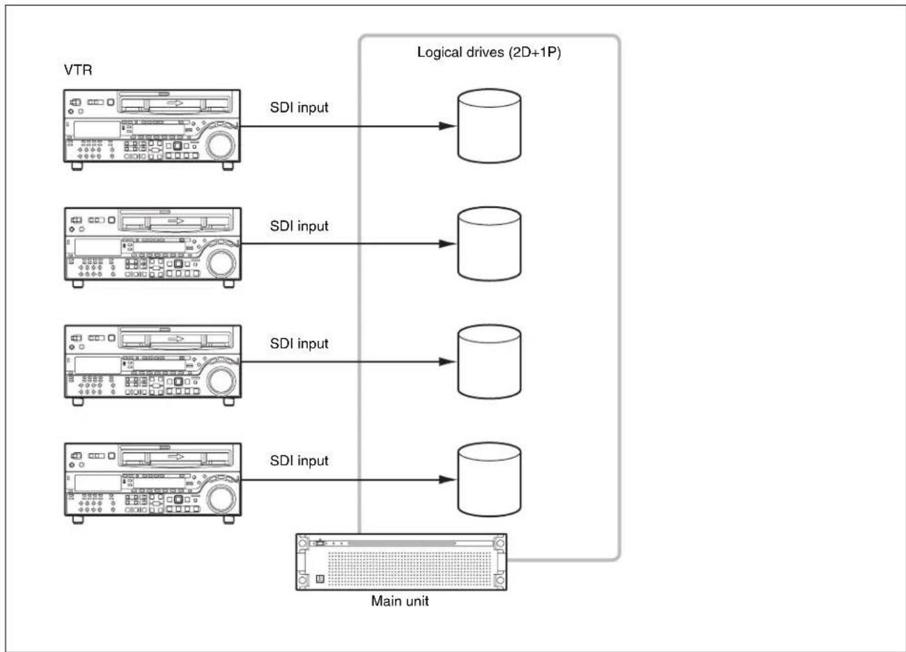
4 inputs
This configuration can be set for XAVC-I, MPEG-HD, IMX, and Uncompressed SD. Connect VTRs to the SDI 1 to 4 connectors, on the XAVC 4K/HD CODEC CARD. When SDI4 is not used for ingesting, you can monitor the high-resolution images of clips in the GUI.
flowchart
graph TD
    A["Operator Operator Manager"] --> B["VTR"]
    A --> C["HD/SD SDI"]
    A --> D["RS422"]
    E["Gigabit Ethernet"] --> F["Main unit"]
    F --> G["USB 3.0"]
    F --> H["Drive unit"]
    I["REF"] --> J["HD/SD SDI"]
    K["REF IN"] --> L["HD/SD SDI"]
    M["Sync signal"] --> N["RS422"]
    O["Sync signal"] --> P["RS422"]
Connections
This configuration uses the REMOTE 3/4 and REMOTE 5/6 connectors.
RAID Configuration Selection
After setting the system configuration, set the RAID configuration so that it has the same number SDI inputs and logical drives as the selected system configuration.
- For 2 inputs/2 outputs: (5D + 1P) × 2
- For 3 inputs/1 output: (3D + 1P) × 3
• For 4 inputs: (2D + 1P) × 4
Notes
- If the RAID configuration is changed, all full-resolution files, proxy files, report files, and work orders written in internal storage are deleted. Before changing the RAID configuration, always transfer or download all data to prevent data loss.
- If the SYSTEM indicator is lit red to indicate an HDD requires replacement, or while rebuilding is in progress due to HDD replacement, the storage performance is reduced and recording/playback may not operate normally. To check whether rebuilding is in progress, check the indicators of each HDD slot with the front panel of the unit removed. Rebuilding is in progress if an indicator is flashing amber.
About RAID configuration
The PWS-300TD2 (PWS-300 + PWA-TD1) supports the following RAID configurations when a total of 12 HDDs are installed.
- 2D + 1P: Contains a total of four logical drives, where each logical drive contains two data HDDs and one parity HDD.
- 3D + 1P: Contains a total of three logical drives, where each logical drive contains three data HDDs and one parity HDD.
- 5D + 1P: Contains a total of two logical drives, where each logical drive contains five data HDDs and one parity HDD.
For 2 inputs/2 outputs
flowchart
graph LR
    A["Main unit"] -->|SDI input| B["Logical drives (5D+1P)"]
    A -->|SDI input| C["External monitorVTR"]
    B -->|SDI output| D["External monitorVTR"]
    C -->|SDI output| E["External monitorVTR"]
For 3 inputs/1 output
flowchart
graph LR
    A["VTR"] -->|SDI input| B["Logical drives (3D+1P)"]
    C["VTR"] -->|SDI input SDI output| D["Logical drives (3D+1P)"]
    E["VTR"] -->|SDI input| F["Main unit"]
    G["External monitor"] --> B
    G --> D
    G --> F
For 4 inputs
flowchart
graph LR
    A["VTR"] --> B["SDI input"]
    B --> C["Logical drives (2D+1P)"]
    D["Main unit"] --> E["SDI input"]
    E --> F["Logical drives (2D+1P)"]
    G["Main unit"] --> H["SDI input"]
    H --> I["Logical drives (2D+1P)"]
Setting the RAID configuration
Set the RAID configuration using "maxView Storage Manager" RAID card management software.
1 Select [System and Security] > [Administrative Tools] > [Computer Management] in [Control Panel].
2 Select [Storage] > [Disk Management] in the tree on the left hand side.
3 Right-click the RAID disk, then click [Delete Volume...] to delete the volume. Click [Yes] when the confirmation dialog box is displayed.
4 Delete all volumes in the RAID in the same way as step 3.
5 Click the maxViewStorageManager icon on the desktop.
A browser window appears.
6 Enter the user name (pws) and password (pws).
7 Select the logical device you want to delete, and click the [Delete Logical Device] icon.
8 Select the controller, and click the [Restore Configuration] icon.
A dialog for selecting a configuration appears.
9 Click the [Choose File] button, and select a configuration file in the C:\Users\Public\Documents folder.
10 Select [Force Logical Device Size] in [Choose The Force Option].
11 Click the [Restore] button.
The configuration starts. When the configuration is completed, the specified logical drive appears.
12 Select [System and Security] > [Administrative Tools] > [Computer Management] in [Control Panel].
13 Select [Storage] > [Disk Management] in the tree on the left hand side.
14 Right-click a logical disk for which [Online] is displayed, and select [Convert to GPT Disk].
15 Right-click a partition for which [Unallocated] is displayed on the RAID disk, and click [Next].
16 Leave the default settings as-is, and click [Next].
17 Set [Allocation unit size] to [64k], and click [Next].
18 Click [Finish].
Formatting of the volume commences.
19 Format all volumes in the RAID configuration in the same way.
20 Restart the unit.
Name and Function of Parts
This section describes the functions of the cards installed in the PCIe card slots.
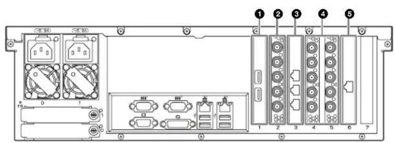
①USB 3.0 connectors
Connect to drive units using USB cables.
Notes
• The USB 3.0 ports support USB Power Delivery.
- Use SuperSpeed USB cables.
②HD-SDI connectors (XAVC 4K/HD CODEC CARD) (when option is selected)
Comprises, from the top, SDI 1 to SDI 4 connectors and REF IN connector. Connect the SDI 1 to SDI 4 connectors to XAVC-compatible VTRs and external monitors for SDI signal input/output. Connect a sync reference signal to the REF IN connector
③ Remote connector (RS422 REMOTE CTRL CARD)
The connectors are named Remote 1/2, Remote 3/4, and Remote 5/6 from the top. Connect to a VTR using an RJ-45 to D-sub adaptor cable (supplied) and a commercially available 9-pin remote cable for remote control of the VTR. You can connect to two VTRs using a single RJ-45 to D-sub adaptor cable and two 9-pin remote cables.
④HD-SDI connectors (SSTP CODEC CARD × 2)
Comprises, from the top, SDI 1 to SDI 4 connectors and REF IN connector. Connect the SDI 1 to SDI 4 connectors to SStP-compatible VTRs and external monitors for SDI signal input/output. Connect a sync reference signal to the REF IN connector.
⑤10 Gigabit Ethernet connector (10GbE NIC) (when option is selected)
Connect to a 10 Gigabit Ethernet network.
Setting Up
Initial Settings
Before using the unit, configure the Windows settings within the unit. Configure settings in accordance with the PWS-300 Operation Guide. Then, configure the following items.
Setting the service password
When setting/modifying the “pws” user password, set the service password as follows.
1 Double-click [Services] under [Administrative Tools] in the [System and Security] control panel.
2 Right-click "Apache Tomcat 7.0 Tomcat7" in the Services list and select [Properties].
3 Open the [Log On] tab.
4 Click [This account], enter “.\pws” and then enter a password for user “pws” under [Password].
5 Click the [Apply] button, then click [OK] to close the dialog.
6 Select "Sony Ingest Service" in the Services list, and repeats steps 2 to 5.
Displaying the Web Application
You connect to the unit via the network from a client PC and use the web application in a web browser on the client PC to control and configure the unit.
Recommended client PC environment
CPU: Core i5 3 GHz or higher Memory: 4 GB or higher OS: Windows 7 Pro 32/64-bit Windows 8/8.1 Pro 32/64-bit Mac OS X 10.8/10.9
Web browser: Google Chrome 40 or later (update to the latest version)
Display resolution: 1366 × 768 pixels or higher
Connect a computer satisfying the above conditions to the LAN 1 or LAN 2 connector on the rear panel of the unit. Enter "https://(IP_address):8443/tds or https://pws-300
Enter the user name and password when the login screen appears.
The following user name and password are configured by default.
User name: admin
Password: tds
System Settings
Configure the system on the Setting screen in the web application.
Log in as a user with administrator privileges when logging in to the web application.
For details about operating the web application, refer to the Help of the application.
Changing the interface language
You can change the interface language of the web application.
Select the language in [Language] on the [My Settings] page of the Setting screen.
Operation frequency selection
Select the operation frequency of the system. You select the frequency under [Ingest Settings] on the [Ingest] page of the Setting screen.
Adding users
To add user accounts in addition to the default admin account, add new users on the [Users] page of the Setting screen.
Registering a transfer destination
To transfer ingested clips to a cartridge or network server, register the transfer destination on the [Transfer] page of the Setting screen.
Installing Certificates
Displaying the web application using an https connection from a web browser may display an error message, such as
"The site's security certificate is not trusted!". To connect successfully via https without an error, a root CA certificate (client certificate) corresponding to the server (PWS-300-
The following describes the procedure for installing a certificate using Google Chrome.
Root CA certificate installation procedure
1 Access the web application using https in a web browser.
An error message, such as “The site’s security certificate is not trusted!” appears.
2 Click the lock icon on the left hand end of the address bar.
3 Click [Certificate information] in the popup window.
The [Certificate] dialog appears. Make a note of the certificate issuer "PWS-300-
4 Click the [Details] tab, then click the [Copy to File] button.
The Certificate Export Wizard appears.
5 Click [Next].
6 Select "DER encoded binary X.509 (.CER)," then click [Next].
7 Click the [Browse] button and specify a folder in which to store the certificate, then click [Next].
Exporting of the certificate commences.
8 When the export wizard completion window appears, click [Finish].
9 When the message window appears, click [OK].
10 Click the Chrome menu button, then select [Settings] from the menu.
11 Click [Show advanced settings] on the Settings screen, then click the [Manage certificates] button under [HTTP/SSL].
The [Certificate] dialog appears.
12 Click the [Trusted Root Certification Authorities] tab of the dialog, then click the [Import] button.
The Certificate Import Wizard appears.
13 Click [Next].
14 Click the [Browse] button and select the downloaded file, then click [Next].
15 Check that [Place all certificates in the following store] is selected and that “Trusted Root Certification
Authorities" is displayed in [Certificate store:], then click [Next].
Importing of the certificate commences.
16 When the import wizard completion window appears, click [Finish].
The wizard exits.
17 When the message window appears, click [OK].
18 Click the Chrome menu button and select [Exit] from the menu. Then, relaunch Chrome.
19 Configure name resolution settings so that the issuer "PWS-300-
Library Licenses
Refer to the [Help] menu in the web application for the licenses of each type of library used by the PWA-TD1.
Usage Precautions
Network precautions
Depending on the operating environment, unauthorized third parties on the network may be able to access the system.
We strongly recommend configuring all of the passwords for security purposes.
Configure all the passwords following the procedure on page32.
From a safety standpoint, when using the unit connected with the network, it is strongly recommended to access the Control window via a Web browser and change the access limitation settings from the factory preset values (page32).
Changing the password regularly is also recommended.
Do not browse any other website in the Web browser while making settings or after making settings. Since the login status remains in the Web browser, close the Web browser when you complete the settings to prevent unauthorized third parties from using the unit or harmful programs from running.
Power supply precautions
If the unit is suddenly turned off during operation, data loss may occur. To maintain data integrity, the use of an uninterruptible power supply (UPS) is recommended.
To disconnect the power cord or turn off the breaker, always press the On/Standby button on the unit to stop the unit before proceeding.
Specifications
XAVC 4K/HD CODEC CARD (PWSK-332)
SDI 1 to 4 BNC (4)
HD: SMPTE ST 292-1 compliant
SD: SMPTE ST 259 compliant
REF IN BNC (1)
SMPTE ST 318 compliant, HD tri-level sync (0.6 Vp-p, 75 Ω, sync negative) or SD black burst/composite sync (NTSC: 0.286 Vp-p, 75 Ω, sync negative, PAL: 0.3 Vp-p, 75 Ω, sync negative)
RS422 REMOTE CTRL CARD (PWSK-334)
Remote RJ-45 (3)
Sony VTR Protocol (9-pin) compatible, RJ-45 to D-sub adapter cable (supplied) is required.
SSTP CODEC CARD (PWSK-335) (2)
SDI 1 to 4 BNC (4)
HD: SMPTE ST 292-1 compliant
SD: SMPTE ST 259 compliant
10GbE NIC
One of the following network cards is installed, depending on the option selection.
For information about network cards, visit the following site.
http://www.intel.com/support/go/network/adapter/userguide.html
Intel Ethernet Converged Network Adapter X520
SFP+ (1)
10GBASE-SR, 10GBASE-LR (following SDP+ module is required)
- Intel Ethernet SFP+ SR Optic (E10GSFPSR)
- Intel Ethernet SFP+ LR Optic (E10GSFPLR)
Intel Ethernet Converged Network Adapter X540
RJ-45 (1)
10GBASE-T
Supplied accessories
RJ-45 to D-sub adapter cable
Part No. 1-848-424-12 (SONY) (3)
Design and specifications are subject to change without notice.
SONY WILL NOT BE LIABLE FOR DAMAGES OF ANY KIND RESULTING FROM A FAILURE TO IMPLEMENT PROPER SECURITY MEASURES ON TRANSMISSION DEVICES, UNAVOIDABLE DATA LEAKS RESULTING FROM TRANSMISSION SPECIFICATIONS, OR SECURITY PROBLEMS OF ANY KIND.
- Windows is a registered trademark of Microsoft Corporation in the United States and other countries.
- Google Chrome is a trademark or registered trademark of Google Inc.
Other products or system names appearing in this document are trademarks or registered trademarks of their respective owners. Further, the ®, or ™ symbols are not used in the text.
Table des matières
Présentation.... 37
Connexions (XAVC-I, MPEG-HD, IMX, Uncompressed SD)
flowchart
graph TD
    A["Magnétoscope 1"] -->|RS422| B["Server"]
    C["Magnétoscope 2"] -->|RS422| B
    D["Moniteur externe 1"] -->|SDI HD/SD| B
    E["Moniteur externe 2"] -->|SDI HD/SD| B
    B --> F["RD System"]
    style A fill:#f9f,stroke:#333
    style C fill:#f9f,stroke:#333
    style D fill:#ccf,stroke:#333
    style E fill:#ccf,stroke:#333
- Intel Ethernet SFP+ SR Optic (E10GSFPSR)
- Intel Ethernet SFP+ LR Optic (E10GSFPLR)
flowchart
graph TD
    A["Bediener Bediener Manager"] --> B["Gigabit Ethernet"]
    B --> C["MAZ"]
    C --> D["REF"]
    C --> E["HD/SD-SDI"]
    C --> F["RS422"]
    G["Externer Monitor"] --> H["Haupteinheit"]
    H --> I["HD/SD-SDI"]
    I --> J["User Device"]
    K["User Device"] --> L["User Device"]
    M["User Device"] --> N["User Device"]
    O["User Device"] --> P["User Device"]
    Q["User Device"] --> R["User Device"]
    S["User Device"] --> T["User Device"]
    U["User Device"] --> V["User Device"]
    W["User Device"] --> X["User Device"]
    Y["User Device"] --> Z["User Device"]
    AA["User Device"] --> AB["User Device"]
    AC["User Device"] --> AD["User Device"]
    AE["User Device"] --> AF["User Device"]
    AG["User Device"] --> AH["User Device"]
    AI["User Device"] --> AJ["User Device"]
    AK["User Device"] --> AL["User Device"]
    AM["User Device"] --> AN["User Device"]
    AO["User Device"] --> AP["User Device"]
    AQ["User Device"] --> AR["User Device"]
    AS["User Device"] --> AT["User Device"]
    AU["User Device"] --> AV["User Device"]
    AW["User Device"] --> AX["User Device"]
    AY["User Device"] --> AZ["User Device"]
    BA["User Device"] --> BB["User Device"]
    BC["User Device"] --> BD["User Device"]
    BE["User Device"] --> BF["User Device"]
    BG["User Device"] --> BH["User Device"]
    BI["User Device"] --> BJ["User Device"]
    BK["User Device"] --> BL["User Device"]
    BM["User Device"] --> BN["User Device"]
    BO["User Device"] --> BP["User Device"]
    BQ["User Device"] --> BR["User Device"]
    BS["User Device"] --> BT["User Device"]
    BU["User Device"] --> BV["User Device"]
    BW["User Device"] --> BX["User Device"]
    BY["User Device"] --> BZ["User Device"]
    CA["User Device"] --> CB["User Device"]
    CC["User Device"] --> CD["User Device"]
    CE["User Device"] --> CF["User Device"]
    DG["User Device"] --> DH["User Device"]
    DI["User Device"] --> DJ["User Device"]
    DK["User Device"] --> DL["User Device"]
    DV["User Device"] --> DW["User Device"]
    DX["User Device"] --> DXB["User Device"]
    DXB --> DXC["User Device"]
    DXC --> DXD["User Device"]
    DXD --> DXE["User Device"]
    DXE --> DXF["User Device"]
    DXF --> DXG["User Device"]
    DXG --> DXH["User Device"]
    DXH --> DXHb["User Device"]
    DXHb --> DXHc["User Device"]
    DXHc --> DXHd["User Device"]
    DXHd --> DXHf["User Device"]
    DXHf --> DXHg["User Device"]
Verbindungen

flowchart
graph TD
    A["MAZ 1"] -->|RS422| B["Server Rack"]
    C["MAZ 2"] -->|RS422| B
    D["MAZ 3"] -->|HD/SD-SDI| B
    E["Externer Monitor 1"] -->|HD/SD-SDI| B
    B --> F["Computer"]
①USB 3.0-Anschlüsse
Intel Ethernet Converged Network Adapter X520 SFP+ (1)
- Intel Ethernet SFP+ SR Optic (E10GSFPSR)
- Intel Ethernet SFP+ LR Optic (E10GSFPLR)
Intel Ethernet Converged Network Adapter X540 RJ-45 (1)
10GBASE-T
Connessioni (XAVC-I, MPEG-HD, IMX, Uncompressed SD)

flowchart
graph TD
    A["VTR1"] -->|RS422| B["Monitor esterno 1"]
    C["VTR2"] -->|RS422| D["Monitor esterno 2"]
    B --> E["HD/SD SDI"]
    D --> F["HD/SD SDI"]
    B --> G["RD Unit"]
    D --> H["RD Unit"]
    style A fill:#f9f,stroke:#333
    style C fill:#f9f,stroke:#333
    style B fill:#ccf,stroke:#333
    style D fill:#ccf,stroke:#333
    style E fill:#dfd,stroke:#333
    style F fill:#dfd,stroke:#333
    style G fill:#dfd,stroke:#333
    style H fill:#dfd,stroke:#333
①Connettori USB 3.0
Intel Ethernet Converged Network Adapter X520 SFP+ (1)
- Intel Ethernet SFP+ SR Optic (E10GSFPSR)
- Intel Ethernet SFP+ LR Optic (E10GSFPLR)
Intel Ethernet Converged Network Adapter X540 RJ-45 (1)
10GBASE-T
Conexiones (XAVC-I, MPEG-HD, IMX, Uncompressed SD)

flowchart
graph TD
    A["VTR1"] -->|RS422| B["Monitor externo 1"]
    A -->|RS422| C["Monitor externo 2"]
    D["VTR2"] -->|RS422| E["Monitor externo 1"]
    D -->|RS422| F["Monitor externo 2"]
    B --> G["HD/SD SDI"]
    C --> H["HD/SD SDI"]
    E --> I["HD/SD SDI"]
    F --> J["HD/SD SDI"]
①Conectores USB 3.0
Intel Ethernet Converged Network Adapter X520 SFP+ (1)
- Intel Ethernet SFP+ SR Optic (E10GSFPSR)
- Intel Ethernet SFP+ LR Optic (E10GSFPLR)
Intel Ethernet Converged Network Adapter X540
RJ-45 (1)
10GBASE-T
flowchart
graph TD
    A["操作员 操作员 管理员"] --> B["天兆以太网"]
    C["天兆以太网"] --> D["外置监视器"]
    D --> E["HD/SD SDI"]
    D --> F["HD/SD SDI"]
    D --> G["HD/SD SDI"]
    D --> H["HD/SD SDI"]
    D --> I["HD/SD SDI"]
    D --> J["HD/SD SDI"]
    D --> K["HD/SD SDI"]
    D --> L["HD/SD SDI"]
    D --> M["HD/SD SDI"]
    D --> N["HD/SD SDI"]
    D --> O["HD/SD SDI"]
    D --> P["HD/SD SDI"]
    D --> Q["HD/SD SDI"]
    D --> R["HD/SD SDI"]
    D --> S["HD/SD SDI"]
    D --> T["HD/SD SDI"]
    D --> U["HD/SD SDI"]
    D --> V["HD/SD SDI"]
    D --> W["HD/SD SDI"]
    D --> X["HD/SD SDI"]
    D --> Y["HD/SD SDI"]
    D --> Z["HD/SD SDI"]
    D --> AA["HD/SD SDI"]
    D --> AB["HD/SD SDI"]
    D --> AC["HD/SD SDI"]
    D --> AD["HD/SD SDI"]
    D --> AE["HD/SD SDI"]
    D --> AF["HD/SD SDI"]
    D --> AG["HD/SD SDI"]
    D --> AH["HD/SD SDI"]
    D --> AI["HD/SD SDI"]
    D --> AJ["HD/SD SDI"]
    D --> AK["HD/SD SDI"]
    D --> AL["HD/SD SDI"]
    D --> AM["HD/SD SDI"]
    D --> AN["HD/SD SDI"]
    D --> AO["HD/SD SDI"]
    D --> AP["HD/SD SDI"]
    D --> AQ["HD/SD SDI"]
    D --> AR["HD/SD SDI"]
    D --> AS["HD/SD SDI"]
    D --> AT["HD/SD SDI"]
    D --> AU["HD/SD SDI"]
    D --> AV["HD/SD SDI"]
    D --> AW["HD/SD SDI"]
    D --> AX["HD/SD SDI"]
    D --> AY["HD/SD SDI"]
    D --> AZ["HD/SD SDI"]
    D --> BA["HD/SD SDI"]
    D --> BB["HD/SD SDI"]
    D --> BC["HD/SD SDI"]
    D --> BD["HD/SD SDI"]
    D --> BE["HD/SD SDI"]
    D --> BF["HD/SD SDI"]
    D --> BG["HD/SD SDI"]
    D --> BH["HD/SD SDI"]
    D --> BI["HD/SD SDI"]
    D --> BJ["HD/SD SDI"]
    D --> BK["HD/SD SDI"]
    D --> BL["HD/SD SDI"]
    D --> BM["HD/SD SDI"]
    D --> BN["HD/SD SDI"]
    D --> BO["HD/SD SDI"]
    D --> BP["HD/SD SDI"]
    D --> BQ["HD/SD SDI"]
    D --> BR["HD/SD SDI"]
    D --> BS["HD/SD SDI"]
    D --> BT["HD/SD SDI"]
    D --> BU["HD/SD SDI"]
    D --> BV["HD/SD SDI"]
    D --> BW["HD/SD SDI"]
    D --> BX["HD/SD SDI"]
    D --> BY["HD/SD SDI"]
    D --> BZ["HD/SD SDI"]
    D --> CA["HD/SD SDI"]
    D --> CB["HD/SD SDI"]
    D --> CC["HD/SD SDI"]
    D --> CD["HD/SD SDI"]
    D --> CE["HD/SD SDI"]
    D --> CF["HD/SD SDI"]
    D --> CG["HD/SD SDI"]
    D --> CH["HD/SD SDI"]
    D --> CI["HD/SD SDI"]
    D --> CJ["HD/SD SDI"]
    D --> CK["HD/SD SDI"]
    D --> CL["HD/SD SDI"]
    D --> CM["HD/SD SDI"]
    D --> CN["HD/SD SDI"]
    D --> CO["HD/SD SDI"]
    D --> CP["HD/SD SDI"]
    D --> CQ["HD/SD SDI"]
    D --> CR["HD/SD SDI"]
    D --> CS["HD/SD SDI"]
    D --> CT["HD/SD SDI"]
    D --> CU["HD/SD SDI"]
    D --> CV["HD/SD SDI"]
    D --> CW["HD/SD SDI"]
    D --> CX["HD/SD SDI"]
    D --> CY["HD/SD SDI"]
    D --> CZ["HD/SD SDI"]
连接(SStP 单)
flowchart
graph LR
    A["VTR1"] -->|RS422 RS422| B["外置监视器 1"]
    B -->|HD/SD SDI HD/SD SDI| C["外置监视器 2"]
    C --> D["外置监视器 2"]
    D -->|IID/SD SDI IID/SD SDI| B
adapter/userguide.html
Intel Ethernet Converged Network Adapter X520 SFP+ (1)
- Intel Ethernet SFP+ SR Optic (E10GSFPSR)
- Intel Ethernet SFP+ LR Optic (E10GSFPLR)
Intel Ethernet Converged Network Adapter X540
RJ-45 (1)
10GBASE-T
随附配件
RJ-45 至 D-Sub 适配器电缆
部件编号 1-848-424-12 (SONY) (3)
设计与技术规格如有变更,恕不另行通知。
flowchart
graph TD
    A["조작자 조작자 관리자"] --> B["外部设备"]
    C["主机"] --> D["终端设备"]
    D --> E["VD T"]
    D --> F["HD/SD SDI"]
    D --> G["HD/SD SDI"]
    D --> H["HD/SD SDI"]
    D --> I["HD/SD SDI"]
    D --> J["HD/SD SDI"]
    D --> K["HD/SD SDI"]
    D --> L["HD/SD SDI"]
    D --> M["HD/SD SDI"]
    D --> N["HD/SD SDI"]
    D --> O["HD/SD SDI"]
    D --> P["HD/SD SDI"]
    D --> Q["HD/SD SDI"]
    D --> R["HD/SD SDI"]
    D --> S["HD/SD SDI"]
    D --> T["HD/SD SDI"]
    D --> U["HD/SD SDI"]
    D --> V["HD/SD SDI"]
    D --> W["HD/SD SDI"]
    D --> X["HD/SD SDI"]
    D --> Y["HD/SD SDI"]
    D --> Z["HD/SD SDI"]
    D --> AA["HD/SD SDI"]
    D --> AB["HD/SD SDI"]
    D --> AC["HD/SD SDI"]
    D --> AD["HD/SD SDI"]
    D --> AE["HD/SD SDI"]
    D --> AF["HD/SD SDI"]
    D --> AG["HD/SD SDI"]
    D --> AH["HD/SD SDI"]
    D --> AI["HD/SD SDI"]
    D --> AJ["HD/SD SDI"]
    D --> AK["HD/SD SDI"]
    D --> AL["HD/SD SDI"]
    D --> AM["HD/SD SDI"]
    D --> AN["HD/SD SDI"]
    D --> AO["HD/SD SDI"]
    D --> AP["HD/SD SDI"]
    D --> AQ["HD/SD SDI"]
    D --> AR["HD/SD SDI"]
    D --> AS["HD/SD SDI"]
    D --> AT["HD/SD SDI"]
    D --> AU["HD/SD SDI"]
    D --> AV["HD/SD SDI"]
    D --> AW["HD/SD SDI"]
    D --> AX["HD/SD SDI"]
    D --> AY["HD/SD SDI"]
    D --> AZ["HD/SD SDI"]
    D --> BA["HD/SD SDI"]
    D --> BB["HD/SD SDI"]
    D --> BC["HD/SD SDI"]
    D --> BD["HD/SD SDI"]
    D --> BE["HD/SD SDI"]
    D --> BF["HD/SD SDI"]
    D --> BG["HD/SD SDI"]
    D --> BH["HD/SD SDI"]
    D --> BI["HD/SD SDI"]
    D --> BJ["HD/SD SDI"]
    D --> BK["HD/SD SDI"]
    D --> BL["HD/SD SDI"]
    D --> BM["HD/SD SDI"]
    D --> BN["HD/SD SDI"]
    D --> BO["HD/SD SDI"]
    D --> BP["HD/SD SDI"]
    D --> BQ["HD/SD SDI"]
    D --> BR["HD/SD SDI"]
    D --> BS["HD/SD SDI"]
    D --> BT["HD/SD SDI"]
    D --> BU["HD/SD SDI"]
    D --> BV["HD/SD SDI"]
    D --> BW["HD/SD SDI"]
    D --> BX["HD/SD SDI"]
    D --> BY["HD/SD SDI"]
    D --> BZ["HD/SD SDI"]
    D --> CA["HD/SD SDI"]
    D --> CB["HD/SD SDI"]
    D --> CC["HD/SD SDI"]
    D --> CD["HD/SD SDI"]
    D --> CE["HD/SD SDI"]
    D --> CF["HD/SD SDI"]
    D --> CG["HD/SD SDI"]
    D --> CH["HD/SD SDI"]
    D --> CI["HD/SD SDI"]
    D --> CJ["HD/SD SDI"]
    D --> CK["HD/SD SDI"]
    D --> CL["HD/SD SDI"]
    D --> CM["HD/SD SDI"]
    D --> CN["HD/SD SDI"]
    D --> CO["HD/SD SDI"]
    D --> CP["HD/SD SDI"]
    D --> CQ["HD/SD SDI"]
    D --> CR["HD/SD SDI"]
    D --> CS["HD/SD SDI"]
    D --> CT["HD/SD SDI"]
    D --> CU["HD/SD SDI"]
    D --> CV["HD/SD SDI"]
    D --> CW["HD/SD SDI"]
    D --> CX["HD/SD SDI"]
    D --> CY["HD/SD SDI"]
    D --> CZ["HD/SD SDI"]
연결 (SStP Single)
flowchart
graph LR
    A["VTR1"] -->|RS422 RS422| B["HD/SD SDI HD/SD SDI"]
    B --> C["VTR2"]
    D["외부 모니터 1"] -->|HD/SD SDI HD/SD SDI| B
    E["외부 모니터 2"] -->|HD/SD SDI HD/SD SDI| B
연결 (XAVC-I, MPEG-HD, IMX, Uncompressed SD)
flowchart
graph TD
    A["VTR1"] -->|RS422| B["Internal Interface"]
    C["VTR2"] -->|RS422| B
    B --> D["Computer 1: HD/SD SDI"]
    B --> E["Computer 2: HD/SD SDI"]
    style A fill:#f9f,stroke:#333
    style C fill:#f9f,stroke:#333
    style B fill:#ccf,stroke:#333
    style D fill:#cfc,stroke:#333
    style E fill:#cfc,stroke:#333
①USB 3.0 커넥터
Intel Ethernet Converged Network Adapter X520
SFP+ (1)
10GBASE-SR, 10GBASE-LR
(다음 SDP+ 모듈 필요)
•Intel Ethernet SFP+ SR
Optic(E10GSFPSR)
•Intel Ethernet SFP+ LR
Optic(E10GSFPLR)
Intel Ethernet Converged Network Adapter X540
RJ-45 (1)
10GBASE-T
부속 액세서리
The material contained in this manual consists of information that is the property of Sony Corporation and is intended solely for use by the purchasers of the equipment described in this manual.
Sony Corporation expressly prohibits the duplication of any portion of this manual or the use thereof for any purpose other than the operation or maintenance of the equipment described in this manual without the express written permission of Sony Corporation.

- 目次
- 概要 3
- 各部の名称と働き 14
- 準備 15
- ①USB 3.0 端子
- 付属品
- Name and Function of Parts.... 31
- Setting Up 32
- Usage Precautions.... 34
- Specifications.... 34
- Overview
- Ingest
- Video quality checking
- Clip storage
- Workflows
- Web application
- Integration with management software
- Codec option
- System Configuration Examples
- inputs/2 outputs
- Notes
- Connections (XAVC-I, MPEG-HD, IMX, Uncompressed SD)
- inputs/1 output
- Connections
- inputs
- RAID Configuration Selection
- About RAID configuration
- For 4 inputs
- Setting the RAID configuration
- Name and Function of Parts
- ①USB 3.0 connectors
- ②HD-SDI connectors (XAVC 4K/HD CODEC CARD) (when option is selected)
- ③ Remote connector (RS422 REMOTE CTRL CARD)
- ④HD-SDI connectors (SSTP CODEC CARD × 2)
- ⑤10 Gigabit Ethernet connector (10GbE NIC) (when option is selected)
- Setting Up
- Initial Settings
- Setting the service password
- Displaying the Web Application
- Recommended client PC environment
- System Settings
- Changing the interface language
- Operation frequency selection
- Adding users
- Registering a transfer destination
- Installing Certificates
- Root CA certificate installation procedure
- Library Licenses
- Usage Precautions
- Network precautions
- Power supply precautions
- Specifications
- XAVC 4K/HD CODEC CARD (PWSK-332)
- RS422 REMOTE CTRL CARD (PWSK-334)
- SSTP CODEC CARD (PWSK-335) (2)
- 10GbE NIC
- Supplied accessories
- Table des matières
- Présentation.... 37
- Connexions (XAVC-I, MPEG-HD, IMX, Uncompressed SD)
- Verbindungen
- ①USB 3.0-Anschlüsse
- Connessioni (XAVC-I, MPEG-HD, IMX, Uncompressed SD)
- ①Connettori USB 3.0
- Conexiones (XAVC-I, MPEG-HD, IMX, Uncompressed SD)
- ①Conectores USB 3.0
- 随附配件
- ①USB 3.0 커넥터
- 부속 액세서리
Brand : SONY
Model : PWA-TD1
Category : Server