
SNTEP154 - Server SONY - Free user manual and instructions
Find the device manual for free SNTEP154 SONY in PDF.


| Product Type | Server |
| Brand | Sony |
| Model | SNTEP154 |
| Form Factor | Rackmount, 1U |
| Dimensions (W x D x H) | 482 x 550 x 44 mm (19 x 21.7 x 1.7 in) |
| Weight | Approximately 8 kg (17.6 lbs) |
| Processor | Intel Xeon Silver 4210 (10 cores, 2.2 GHz) |
| Memory | 32 GB DDR4 ECC (expandable up to 128 GB) |
| Storage | 2 x 2 TB SATA HDD (hot-swappable) |
| Network | Dual Gigabit Ethernet ports |
| Power Supply | Dual redundant 750W PSUs |
| Cooling | 4 x 40mm hot-swap fans |
| Operating Temperature | 5°C to 35°C (41°F to 95°F) |
| Management | IPMI 2.0 with dedicated management port |
| Security | TPM 2.0 module, chassis intrusion detection |
| Supported OS | Windows Server, Linux distributions, VMware |
| Maintenance | Tool-less access, hot-swap components |
Frequently Asked Questions - SNTEP154 SONY
User questions about SNTEP154 SONY
0 question about this device. Answer the ones you know or ask your own.
Ask a new question about this device
Download the instructions for your Server in PDF format for free! Find your manual SNTEP154 - SONY and take your electronic device back in hand. On this page are published all the documents necessary for the use of your device. SNTEP154 by SONY.
USER MANUAL SNTEP154 SONY
Video Network Station
User's Guide
Software Version 1.85
Before operating the unit, please read this manual thoroughly and retain it for future reference.
SNT-EX101/SNT-EX101E
SNT-EX104/SNT-EP104
SNT-EX154/SNT-EP154
SNT-RS1U/SNT-RS3U
IPELA
Table of Contents
Overview
Features 4
How to Use This User's Guide .... 5
System Requirements .... 5
Preparation
Assigning the IP Address to the Camera ...... 6
Assigning an IP address using SNC toolbox ..... 6
Accessing the System Using the Web Browser ... 7
Basic Configuration by the Administrator ...... 9
Precautions for Preventing Access to the Camera
by an Unintended Third Party 10
How to set up 10
Operating the unit
Administrator and User 11
Logging in to System 12
Logging in as a user 12
About Viewers 12
Configuration of Main Viewer 13
Main menu 13
Control panel section 13
Monitor image 15
Plug-in free Viewer 15
Operating the Camera 16
Controlling via the control panel 16
Moving the camera to a preset position ..... 17
Using the Trigger Button 17
Sending a monitor image via e-mail 17
Sending a monitor image to an FTP server ..... 17
Recording a camera image as a still image ..... 17
Controlling alarm output 18
Playing an audio file stored in the system ..... 18
Switching Transmission Mode 18
Using the System Utility 19
SNC Viewer 19
SNC Desktop viewer 20
Administrating the unit
Basic Operations of the Administrator Menu ...22
How to set up the Administrator menu ......22
Configuration of the Administrator menu .....23
Configuring the System — System Menu ......24
System Tab 24
Date & time Tab 25
Superimpose Tab 26
Initialize Tab 27
System log Tab 28
Access log Tab 28
Setting the Camera Image and Audio
— Camera Menu ....28
Common Tab 28
Picture Tab 29
Privacy Masking tab 30
Video codec Tab ....31
Streaming Tab 31
Configuring the Network — Network Menu .....32
Network Tab 32
QoS Tab 34
Dynamic IP address notification Tab — Notifying the IP Address 35
Setting the SSL function — SSL Menu ......37
SSL tab 37
CA certificate tab — Adding the CA certificate for client authentication ....39
How to install the CA certificate .....40
To remove an installed CA certificate ....41
Using the 802.1X Authentication Function
— 802.1X Menu ....42
System configuration of 802.1X network .....42
Common Tab - Basic setting of 802.1X authentication function ....43
Client certificate Tab 44
CA certificate Tab 45
Setting the 802.1X authentication function – Example of Windows Server 2003 ......45
Setting the User — User Menu ....48
Setting the Security — Security Menu .....49
Setting Tab 49
Referer check tab 50
Saving the Camera Position and Action
— Preset position Menu ....51
Position Tab — Saving pan/tilt/zoom position ....51
Position Tour Tab — Setting a position tour ....52
Sending an Image via E-mail — e-Mail (SMTP)
Menu 53
Common Tab — Setting the e-Mail (SMTP) Function .... 53
Alarm sending Tab — Setting the e-mail sending mode when detecting the alarm .... 55
Periodical sending Tab — Setting the periodical e-mail sending mode 56
Abnormal sending tab — Setting the abnormal e-mail sending mode .... 56
Sending Images to FTP Server — FTP client
Menu 57
Common Tab — Setting the FTP client function 57
Alarm sending Tab — Setting the FTP client action when detecting the alarm .... 58
Periodical sending Tab — Setting the periodical FTP client activity .... 59
Recording Images in Memory — Image memory
Menu 60
Common Tab — Setting the image memory function 61
Alarm recording Tab — Setting the Image memory function when detecting the alarm ... 62
Periodical recording Tab — Setting the periodical recording mode 63
Folder structure of image memory 64
Downloading Images from the system
— FTP server Menu 65
Setting the Alarm Output
— Alarm output Menu 67
Alarm output Tab 67
Outputting Audio Linked to Alarm Detection
— Voice alert Menu 69
Voice alert 1, 2, 3 Tab 69
Setting the Operations from the Viewer — Trigger
Menu 70
Setting the Schedule
— Schedule Menu 72
Setting the Alarm Buffer — Alarm buffer
Menu 73
Setting the Sensor input/Camera tampering detection/Motion detection/Audio detection
— Event detection menu 73
Sensor input tab — Set the sensor input ..... 73
Camera tampering detection tab — Set the camera tampering detection .... 74
Motion detection tab — Set the motion/VMF detection 74
What are VMF functions-Video Motion Filter ....74
Setting items for motion detection .....75
VMF setting items 77
Simple motion detection function ....81
Audio detection tab — Set the audio detection ....81
Transmitting with External Equipment
— PTZ control I/F Menu ....82
Configuring the Viewer — Viewer Menu .....83
Layout tab 83
HTML output tab 86
Others
Using the SNC toolbox ....87
Using the SNC audio upload tool — Transmitting
Audio to Camera 87
Using the SNC video player — Playing a Video/
Audio File Recorded with the unit ....88
Installing the SNC video player ....88
Using the SNC video player 88
Assigning the IP Address to the unit using ARP
Commands 89
Using the SNMP 90
-
Inquiry Commands ....90
-
Setting Commands ....91
Glossary 92
Index 95
Overview
Features
- High-quality live images from camera can be monitored at a maximum frame rate of 30 fps.
- XDNR and Visibility Enhancer enable clearer images for streaming.
- Three video compression modes (video codecs) JPEG/MPEG4/H.264 are supported.
- Single codec mode and dual codec modes are available.
- Intelligent motion detection, camera tampering detection, audio detection alarm functions are provided (SNT-EX101, SNT-EX101E, SNT-EX104, SNT-EX154).
- Basic motion detection is provided (SNT-EP104, SNT-EP154).
- High-performance Echo Canceler purely eliminates acoustic echo propagated from a loudspeaker to a microphone of the camera (SNT-EX101/EX101E/EX104/EX154).
- Ambient noise filter reduces noise for clear sound streaming (SNT-EX101/EX101E/EX104/EX154).
- With Dynamic Range Compressor, slight sound can be auto-adjusted at an optimum volume and streamed out (SNT-EX101, SNT-EX101E, SNT-EX104, SNT-EX154).
- Up to 10 users can view images from one camera at the same time.
- Date/time can be superimposed on the image.
- With Edge storage, video or audio signal can be recorded from the alarm detection results, such as network block, and stream the live image and sound with same protocol (SNT-EX101, SNT-EX101E, SNT-EX104).
NOTICE TO USERS
© 2009 Sony Corporation. All rights reserved. This manual or the software described herein, in whole or in part, may not be reproduced, translated or reduced to any machine readable form without prior written approval from Sony Corporation.
SONY CORPORATION PROVIDES NO WARRANTY WITH REGARD TO THIS MANUAL, THE SOFTWARE OR OTHER INFORMATION CONTAINED HEREIN AND HEREBY EXPRESSLY DISCLAIMS ANY IMPLIED WARRANTIES OF MERCHANTABILITY OR FITNESS FOR ANY PARTICULAR PURPOSE WITH REGARD TO THIS MANUAL, THE SOFTWARE OR SUCH OTHER INFORMATION. IN NO EVENT SHALL SONY CORPORATION BE LIABLE FOR ANY INCIDENTAL, CONSEQUENTIAL OR SPECIAL DAMAGES, WHETHER BASED ON TORT, CONTRACT, OR OTHERWISE, ARISING OUT OF OR IN CONNECTION WITH THIS MANUAL, THE SOFTWARE OR OTHER INFORMATION CONTAINED HEREIN OR THE USE THEREOF.
Sony Corporation reserves the right to make any modification to this manual or the information contained herein at any time without notice. The software described herein may also be governed by the terms of a separate user license agreement.
- “IPELA” and are trademarks of Sony Corporation.
- Microsoft, Windows and Internet Explorer are registered trademarks of Microsoft Corporation in the United States and/or other countries.
- Java is a trademark of Sun Microsystems, Inc. in the United States and other countries.
- Intel and Pentium are registered trademarks of Intel Corporation or its subsidiaries in the United States and other countries.
- Adobe, Adobe Reader and Adobe Flash are trademarks of Adobe Systems Incorporated in the United States and/or other countries.
All other company and product names are trademarks or registered trademarks of the respective companies or their respective makers.
How to Use This User's Guide
This User's Guide explains how to operate the video network station from a computer.
The User's Guide is designed to be read on the computer display.
This section gives tips on making the most of the User's Guide-read it before you operate the camera.
Jumping to a related page
When you read the User's Guide on the computer display, you can click on a sentence to jump to a related page.
Software display examples
Note that the displays shown in the User's Guide are explanatory examples. Some displays may be different from the ones that appear in actual use.
The illustrations of the camera and menu display in the User's Guide show the SNT-EX104 video network station as an example.
Printing the User's Guide
Depending on your system, certain displays or illustrations in the User's Guide, when printed out, may differ from those that appear on your screen.
Installation Manual (printed matter)
The supplied Installation Manual describes the names and functions of parts and controls of the video network station, connection examples, and how to set up the camera. Be sure to read the Installation Manual before hand.
System Requirements
The following computer environment is necessary for the computer to display images and the controls of the camera.
(November 2014)
CPU
Intel Core 2 Duo, 1.8 GHz or higher
Memory
1 GB or more
os
Microsoft Windows XP, Windows Vista (32bit version only), Windows 7 (32-bit version, 64-bit version),
Windows 8 Pro (32-bit version, 64-bit version)*,
Windows 8.1 Pro (32-bit version, 64-bit version)*
Authorized editions:
Windows XP: Professional
Windows Vista: Ultimate, Business
Windows 7: Ultimate, Professional
Windows 8: Pro
Windows 8.1: Pro
Microsoft DirectX 9.0c or higher
Web Browser
Windows Internet Explorer Ver. 7.0, Ver. 8.0, Ver. 9.0, Ver. 10.0*
Firefox Ver. 25.0 (Plug-in free viewer only)
Safari Ver. 5.1 (Plug-in free viewer only)
Google Chrome Ver. 31.0 (Plug-in free viewer only)
Display
1280 × 1024 pixels or higher
* In case of Windows 8 or Windows 8.1, use the Internet Explorer desktop user interface (desktop UI) edition.
Preparation
The Preparation section explains what the administrator has to prepare for monitoring images after installation and connection of the camera.
Assigning the IP Address to the Camera
To connect the camera to a network, you need to assign a new IP address to the camera when you install it for the first time.
Before starting, connect the camera, referring to "Connecting the Camera to a Local Network" in the supplied Installation Manual.
Consult the administrator of the network about the assigned IP address.
Assigning an IP address using SNC toolbox
1 Insert the CD-ROM in your CD-ROM drive. A cover page appears automatically in your Web browser.
If it does not appear automatically in the Web browser, double-click the index.htm file on the CD-ROM.
When you are using Windows Vista, the “Auto play” pop-up may appear.
2 Click the Setup icon of SNC toolbox.
The "File Download" dialog appears.
3 Click File Open.
4 Install "SNC toolbox" on your computer using the wizard.
For details of the software installation and usage, see the Application Guide.
5 Assign the IP address. Assign the IP address using the installed SNC toolbox.
For details, see “Using the SNC toolbox” - “Assigning an IP address” in the Application Guide.
Tips
- Download the latest installer or Application Guide of SNC toolbox from the following URL: http://www.sony.net/ipela/snc
- SNC toolbox stands for Sony Network Camera toolbox.
Accessing the System Using the Web Browser
After the IP address has been assigned to the unit, check that you can actually access the system using the Web browser installed on your computer. Use Internet Explorer as a Web browser.
1 Start the Web browser on the computer and type the IP address of the unit in the URL address bar.

The viewer window is displayed.
Display sample

Note
When accessing the camera, images will not be displayed in the following conditions.
- When the maximum number of viewers exceeds 10 However, if the e-Mail (SMTP) function or the FTP client function is set to On, the maximum number of viewers will be 3.
• The bit rate including new requests exceeds 16Mbps
Using the SSL function
Note
The model on sale in China does not support the SSL function.
When Internet Explorer is used
When you enter the unit IP address, "Certificate Error" may appear according to the status of the certificate set on the system. In this case, click Continue to this website (not recommended). to continue.
The welcome page appears (in SSL communication).

When "Allow HTTP connection for some clients" (page 37) is checked
To use HTTP and SSL connections separately to access, enter the following in the address box of the browser.
For HTTP connection

For SSL connection

When the viewer of the unit is displayed for the first time
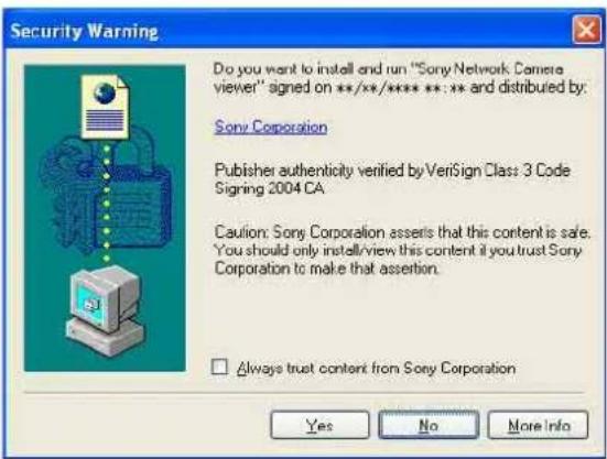
"Security Warning" is displayed. When you click Yes, ActiveX control is installed and the viewer is displayed.
Notes
- If Automatic configuration is enabled in the Local Area Network (LAN) settings of Internet Explorer, the image may not be displayed. In that case, disable Automatic configuration and set the Proxy server manually. For the setting of the Proxy server, consult your network administrator.
- When you install ActiveX Control, you should be logged in to the computer as Administrator.
Tip
The software is optimized for Internet Explorer using medium font.
To display the viewer correctly
To operate the viewer correctly, set the security level of Internet Explorer to Medium or lower, as follows:
1 Select Tools from the menu bar for Internet Explorer, then select Internet Options and click the Security tab.
2 Click the Internet icon (when using the camera via the Internet), or Local intranet icon (when using the camera via a local network).
3 Set the slider to Medium or lower. (If the slider is not displayed, click Default Level.)
When using antivirus software, etc., on the computer
- When you use antivirus software, security software, personal firewall or pop-up blocker on your computer, the system performance may be reduced, for example, the frame rate for displaying the image may be lower.
- The Web page displayed when you log in to the camera uses JavaScript. The display of the Web page may be affected if you use antivirus software or other software described above on your computer.
Basic Configuration by the Administrator
You can monitor the camera image by logging in with the initial conditions set for this video network station.
You can also set various functions according to the installing position, network conditions or purpose of the camera.
We recommend you configure the following items before monitoring images from the camera.
| Setting contents Setting menu | |
| Set the format of the image sent from the unit. Video codec Tab (page 31) | |
| Select the brightness of the image sent from the unit. Brightness (page 29) | |
| Select the quality of the image sent from the unit. Video codec Tab (page 31) | |
| Select the view size of the image. View size (page 13) | |
| Select whether the audio from the external microphone is sent or not. Audio codec (page 28) | |
| Synchronize the date and time of the unit with those of the computer. Date & time Tab (page 25) | |
| Make the setting for sending the monitor image attached to an e-mail. | e-Mail (SMTP) Menu (page 53) |
| Set the user access right for the unit. User Menu (page 48) | |
| Set a place to be watched beforehand. Preset position Menu (page 51) | |
Precautions for Preventing Access to the Camera by an Unintended Third Party
The camera may be accessed by an unintended third party on the network, depending on the usage environment. Changing the user name and password of the camera administrator from the default settings is highly recommended for security reasons. If the camera is accessed by an unintended third party, there may be an undesired effect, such as operations or settings to block monitoring, etc.
The camera can be fraudulently accessed in a network environment where a device is connected or connectable to the network without the administrator's permission, or a PC or other network device connected to the network can be used without any permission. Connect to these environments at your own risk. To prevent unauthorized access to the camera, set it according to the following steps.
Do not use the browser you use to set the camera to access other websites while you set or after setting the camera. You will remain logged in to the camera as long as the browser is open, so to prevent an unintended third party's use or execution of malicious programs, close the browser after you finish setting the camera.
How to set up
1 Set the network address of the camera using SNC toolbox.
For details about how to use SNC toolbox, refer to the application guide.
After this step, do not use SNC toolbox to change the network settings of the camera. Use SNC toolbox to search for the camera only.
2 Start the web browser and set the SSL function to Enable in the camera settings.
For details, refer to “Setting the Security — Security Menu” in the Administrator menu on page 49.
3 Restart the web browser and access the camera again.
4 Set the user name and password of the administrator of the camera. For details, refer to “Setting the Security — Security Menu” in the Administrator menu on page 49.
5 Check the Referer check checkbox. For details, refer to “Setting the Security — Security Menu” in the Administrator menu on page 49.
6 When you use the e-Mail (SMTP) function, set the TLS function to On. Use a mail server that supports the TLS function.
For details, refer to “Sending an Image via E-mail — e-Mail (SMTP) Menu” in the Administrator menu on page 53.
Hereafter, use the camera using the SSL connection. When you use the FTP server or the FTP client function, use them in an environment where the network cannot be intercepted by a third party. The SSL connection cannot be used for the FTP server or the FTP client function.
Note
The model on sale in China does not support the SSL function.
Operating the unit
This section explains how to monitor the image from the camera using your Web browser (Internet Explorer).
The functions of the unit should be set by the Administrator. For the setting of the unit, see “Administrating the unit” on page 22.
Administrator and User
This video network station identifies those who log in as the Administrator or User.
The Administrator can use all the functions of this video network station, including camera settings. The User can use the functions for monitoring the image and audio from the camera, and control the camera. The Viewer mode setting is used to restrict the user's access rights. There are five types of users.
Each type of user can use the corresponding functions below.
| Function Administrator | User | |||||
| Full Pan/T | Tilt Preset | position | Light View | |||
| Monitor a live image ● | ● | ● | ● | |||
| View the date and time ● | ● | ● | ● | |||
| Control the frame rate (JPEG mode only) ● | ● | - | - | - | ||
| Control the image view size ● | ● | ● | ● | - | ||
| Save a still image and movie in the computer ● | ● | ● | ● | ● | - | |
| Send an image file to the FTP server | ● | ● | - | - | - | - |
| Send an image attached to an c-mail | ● | ● | - | - | - | - |
| Record an image in the memory | ● | ● | - | - | - | - |
| Control the alarm output of the I/O port on the unit | ● | ● | - | - | - | - |
| Play an audio file (Voice alert) * | ● | ● | - | - | - | - |
| Switch the TCP/UDP transmission mode (Available in MPEG4/H.264 mode only) | ● | ● | - | - | - | - |
| Call the preset position * | ● | ● | ● | ● | - | - |
| Perform the pan/tilt/zoom operation * | ● | ● | ● | - | - | - |
| Receive audio * | ● | ● | ● | ● | ● | |
| Select the codec mode | ● | ● | ● | ● | ● | |
| Control the setting menu | ● | - | - | - | - | - |
●Usable function
- Not usable function
* SNT-EX101/SNT-EX101E/SNT-EX104/SNT-EX154 only
The access rights of the administrator and the user can be set in “Setting the User — User Menu” of the Administrator menu on page 48.
Logging in to System
Logging in as a user
1 Start the Web browser on your computer and type the IP address of the system you want to monitor.
| Address | http://192.168.0.100 |
The viewer is displayed.
Display sample:
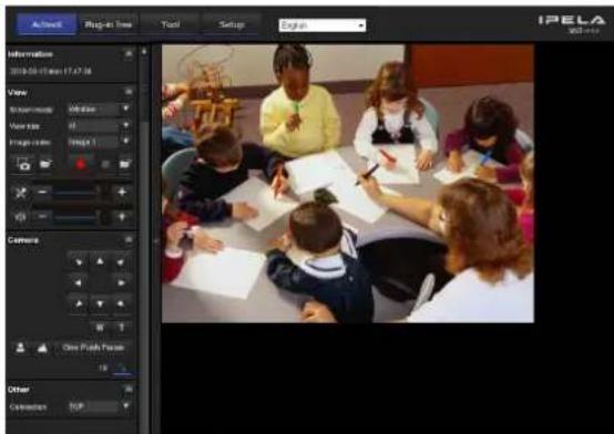
Three types of viewer are available: ActiveX Viewer, Plug-in free Viewer and custom homepage. By default, ActiveX Viewer is displayed. To switch the viewer, make changes to the Viewer menu (page 83).
Note
If the main viewer does not start correctly, the security level of the Internet Explorer may be set to higher than Medium. See “To display the viewer correctly” on page 8 and check the security level.
About Viewers
You can use the following viewers.
ActiveX Viewer
This viewer can monitor the camera image in any of the JPEG, MPEG4 and H.264 video codecs.
You must install this viewer when you access the main viewer for the first time.
When you display the main viewer of the unit for the first time
When you access the video network station using ActiveX Viewer for the first time, the Security Warning
appears. Click Yes and install ActiveX Control. You can use all the functions of the viewer with ActiveX Control.
Plug-in free Viewer
This viewer allows the user to select from three image display methods: JPEG, JPEG/FLASH or ActiveX Viewer.
JPEG method: JPEG images will be displayed in sequence.
JPEG/FLASH method: JPEG images will be displayed in sequence.
ActiveX Viewer method: The image can be viewed when the image display is set to JPEG, MPEG4 or H.264.
Notes
- If Automatic configuration is enabled in the Local Area Network (LAN) Settings of Internet Explorer, the camera image may not be displayed. In that case, disable Automatic configuration and set the Proxy server manually. For the setting of the Proxy server, consult your network administrator.
- When you install ActiveX Control, you should be logged in to the computer as the Administrator.
Tip
Every page of this software is optimized for Internet Explorer in Medium font.
Configuration of Main Viewer
This section explains the functions of the parts and controls of the main viewer. For a detailed explanation on each part or control, see the specified pages.
Main viewer using ActiveX Viewer
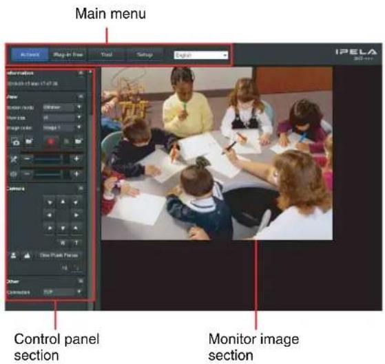
Main menu
ActiveX
Displays the ActiveX viewer.
Plug-in free
Displays the Plug-in free viewer.
Tool
You can download system utility from here. (page 19) This operation is only available when you are logged in as administrator.
Set up
Click to display the Administrator menu. (page 22) You can operate this function only when logging in as the administrator.
Language
Set language from pull-down.
Control panel section
You can drag the panels to the monitor screen and configure them.
To return to the operation panel, drag the panel and configure the operation panel.
Click the 📄 hide the detail setting menu or click it again to show the menu.
Information panel
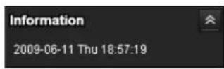
Check the date and time here.
View panel
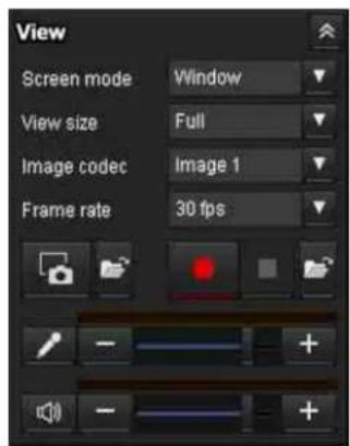
You can change the screen mode, size of the image, image codec mode and frame rate. Also, still images and movies can be saved (movie saving can also be stopped) from here. Microphone and audio output levels can be adjusted.
Screen Mode
Select Window or Full Screen.
View size
Selects the view size to be displayed.
Click View size list box to select the view size.
Select x1 to display images set in Image size of the Camera menu. (page 31)
Select Full to display images according to the view size. Select Fit to display images according to the view size, with fixed aspect ratio.
Image Codec
Select an image codec mode.
Frame rate
(Displayed only when the camera image is in JPEG.) Selects the frame rate to transmit images.

(Capture)
Click to capture a still image shot by the camera and to store it in the computer. Click to open the folder to be saved.
Note
In the case of Windows Vista, Windows 7, Windows 8 or Windows 8.1, if "Enable Protected Mode" is checked in Control Panel-Internet Option-Security, still images cannot be shot.

(Run)/ (Stop Save Video)
Runs and stops Save Video. Click to open the folder to be saved.
Note
In the case of Windows Vista, Windows 7, Windows 8 or Windows 8.1, if "Enable Protected Mode" is checked in Control Panel-Internet Option-Security, video content cannot be saved.
Volume
(Displayed when Audio codec (page 28) is set to On.)
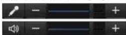
Adjust the microphone volume by moving the each slider bar.
When you click 📄 e icon changes to an ✗e microphone input stops. To input the microphone, click ✗ again.
When you click 📄 the icon changes to an 📄 the microphone output stops. To output the microphone, click 📄 again.
Notes
- This operation is not available on the SNT-EP104 or SNT-EP154.
• Voice alert configuration is only available for CH1 on the SNT-EX154.
Camera control panel
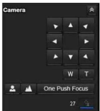
On this panel, you can control the pan/tilt/home position of the camera, adjust the zoom and switch focus mode (page 16). In addition, you can obtain authority to operate the camera when the exclusive control mode is on.
Notes
- This operation is not available on the SNT-EP104 or SNT-EP154.
• To operate the camera, it is necessary to have a camera connected, and the connection/setting set correctly.
Pan/Tilt control
Click the arrow button the direction in which you want to move the camera. Keep it pressed to move the camera continuously.
Zoom control
Press w zoom out, and press to zrom in. Zooming continues while the button remains pressed.
Focus control
To focus on a nearby object, press ▲ to focus on a distant object, press ▲ By pressing ▲ One Push Focus ▲ to the optimum position.
Note
To control the focus manually, set Focus mode of the Camera menu to Manual (page 28).

(Exclusive control)
Click this button to display the time remaining for operation authority. However, if operation authority has not been obtained, the waiting time is displayed.
Trigger panel

The above is displayed only when Viewer mode (page 49) is set to Full, and one or more triggers are enabled in the Trigger menu (page 70).
The configured functions are displayed as buttons on this panel.
Click the function button you want to use on the Trigger panel. The selected function is activated. The selectable functions are as follows:
- send still image files attached to an e-mail (page 17)
- send still image files to an FTP server (page 17)
- record still image files in the built-in memory or USB memory (not supplied) (page 17)
• control the alarm output (page 18) - play the audio file stored in the system (page 18)
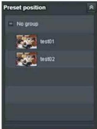
Preset position panel

The above is displayed only when one or more preset positions are stored in memory.
The registered preset position is displayed with a thumbnail.
Select the Preset position name from the list. The camera will move to the preset position that you have stored in memory using the Preset position menu.
Notes
- This operation is not available on the SNT-EP104 or SNT-EP154.
• To operate the camera, it is necessary to have a camera connected, and the connection/setting set correctly.
Others panel
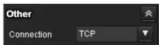
(The Other panel is displayed in the case of an MPEG4 or H.264 image.)
You can switch between TCP and UDP (Unicast/Multicast).
Each click switches the transmission mode of the video/audio data between TCP mode, Unicast mode, and Multicast mode (page 18).
Monitor image

natural_image
Group of children and adults sitting around a table engaged in a classroom activity, drawing or writing (no visible text or symbols)The image shot by the camera is shown here. You can use the camera control panel bar to pan or tilt.
Plug-in free Viewer
Main viewer using Plug-in free Viewer
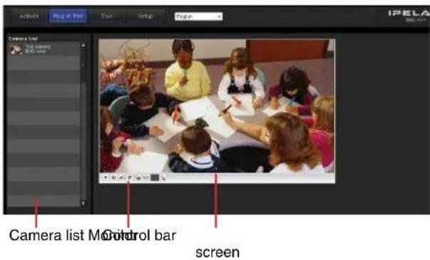
Monitor screen
You can use the tool bar to pan or tilt.
Control bar
The following operation buttons are available.

Setting
You can set the streaming method, image size, frame rate, PTZ operation mode, trigger selection and image codec.
Streaming start button
Starts streaming. (Appears while stops streaming.)
Streaming stop button
Stops streaming. (Appears while streaming.)
Trigger run button
Runs the selected trigger.
(Displayed only when Viewer mode from User menu (page 49) is set to Full, and one or more triggers are enabled in the Trigger menu (page 72).)
P Preset
Select a preset position to move the camera to the registered preset position.
(Displayed only when a camera preset position is registered.)
Save still image button
Captures still images taken by the camera and saves them to the computer.
Audio output volume slider
Use the slider to adjust the volume. Clicking the button will stop sound output.
(Displayed only when ActiveX is set for Streaming method in Setting, and Audio codec in the Camera Menu (page 28) is set to On.)
■ Control waiting time and control time for exclusive control
Exclusive control button
Camera list
The camera list is displayed when Camera list is set to On in the viewer menu (page 84), and at least one camera is registered in the unit list.
Operating the Camera
You can control pan/tilt, zoom and focus.
Notes
- This operation is not available on the SNT-EP104 or SNT-EP154.
• To operate, make sure the connected camera is configured correctly.
Controlling via the control panel
You can operate the camera direction, zoom, and focus by using the control panel for the monitor image currently displayed.

Pan/Tilt control
Click the arrow button in the direction in which you want to move the camera. Keep it pressed to move the camera continuously.
Zoom control
Click w zoom out, and click to zrom in. Zooming continues while the button remains pressed.
Focus control
To focus on a nearby object, click 📂 To focus on a distant object, click 🔊
By clicking the Fion Focus set to the optimum position.
Note
To control the focus manually, set Focus mode of the Camera menu to Manual (page 28).
Moving the camera to a preset position
Select a preset position name from the Preset position panel. The camera will move to the preset position that you have stored in memory using the Preset position menu (page 51).
Multiple preset positions can be organized by group according to setting.
Using the Trigger Button
You can execute various functions by clicking their respective buttons on the Trigger panel.
Sending a monitor image via e-mail
You can send a captured still image by attaching it to an e-mail.
To use this function, you need to make e-Mail (SMTP) active and set the address in the Trigger menu of the Administrator menu properly (page 70).
1 Click e-Mail (SMTP) on the Trigger panel. The still image of the moment you click is captured, and your e-mail with the image file attached is sent to the specified mail address.
Sending a monitor image to an FTP server
You can send a captured still image to the FTP server. To use this function, you need to make FTP active and set the address in the Trigger menu of the Administrator menu properly (page 71).
1 Click FTP client on the Trigger panel. The still image of the moment you click is captured, and the image file is sent to the FTP server.
Recording a camera image as a still image
You can capture a camera image as a still picture and record it.
The still images are recorded in the built-in memory or USB memory (not supplied).
To use this function, you need to make Image memory active and set the details in the Trigger menu of the Administrator menu (page 71).
1 Click Image memory on the Trigger panel. The still image of the moment you click is captured, and the image file is recorded.
Controlling alarm output
You can control Alarm output.
To use this function, you need to make Alarm output active in the Trigger menu of the Administrator menu (page 71).
1 Click Alarm output1 or Alarm output2 on the Trigger panel.
The alarm output is switched by clicking.
The alarm output mode can be selected from
Toggle or Timer of Alarm output 1, 2 (page 71) in the Trigger menu.
Tips
- For the connection of peripheral devices to the alarm output of the I/O port, see the supplied Installation Manual.
- The number of alarm outputs varies by model.
The number of selectable alarm output terminals is as follows:
SNT-EX101/SNT-EX101E: 2
SNT-EX104/SNT-EX154: 4
SNT-EP104/SNT-EP154: None
Playing an audio file stored in the system
You can play an audio file previously stored in the system using the SNC audio upload tool.
To use this function, you need to make Voice alert1,
Voice alert2 and Voice alert3 active in the Trigger menu of the Administrator menu (page 71).
1 Click Voice alert1, Voice alert2 or Voice alert3 on the Trigger panel.
Playback of the selected audio file starts and the playback sound is output from the speaker connected to the system.
Notes
- This operation is not available on the SNT-EP104 or SNT-EP154.
- Voice alert configuration is only available for CH1 on the SNT-EX154.
Switching Transmission Mode
You can select the Transmission mode for video/audio data.
This function can be used when Mode (video codec mode) is set to MPEG4 or H.264 and the ActiveX Viewer is used.
Note
The function may not operate correctly if you use personal firewall software or antivirus software on your computer. In that case, disable the software or select the TCP mode.
1 Select TCP, Unicast or Multicast from the Connection drop-down list in the Others panel.
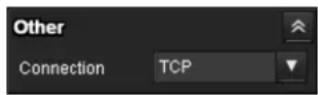
TCP: This is normally selected.
When TCP is selected, HTTP communication is adopted for video communications.
HTTP is the protocol used for reading the usual Web page.
In an environment capable of reading Web pages, you can watch video by selecting the TCP port.
Unicast: When Unicast is selected, RTP (Real-time Transport Protocol) is adopted for video communications. Since RTP is the protocol for running video data, the video playback is smoother than when TCP (HTTP) is selected. If a firewall is installed between the camera and the computer, or depending on the network environment, video may not play back properly when Unicast is selected. In this case, select TCP.
Multicast: This protocol is selectable when Multicast streaming (page 32) is On. When Multicast is selected, RTP (Real-time Transport Protocol) and UDP multicast techniques are adopted for video transmission. By selecting it, the network transmission load of the camera can be reduced. If a router that does not correspond to a multicast or firewall is installed between the camera and the computer, video may not play back properly. In this case, select TCP or Unicast.
Note
When you are connected to a Proxy server, Unicast or Multicast cannot be selected.
Using the System Utility
You can download system utility from the tools tab on the main menu.
This operation is only available when you are logged in as administrator.
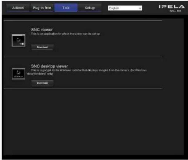
To use the utility, click Download to begin download.
Note
Network camera (SNC-RH124/RS46N/RS46P, SNC-RS44N/RS44P/RH164, SNC-RS86N/RS86P/RS84N/RS84P) and video network station have a common utility. For the video network station, some of the utility functions cannot be used.
SNC Viewer
SNC Viewer is an application which allows you to set the initial state of the viewer.
Installing the SNC viewer
1 Execute the downloaded SNCViewer.msi file.
2 Install the SNC viewer following the instructions on the wizard.
When the license agreement policies are displayed, agree after reading them carefully and install the SNC viewer.
Using the SNC viewer
Click SNC viewer in the control panel.
Connection tab
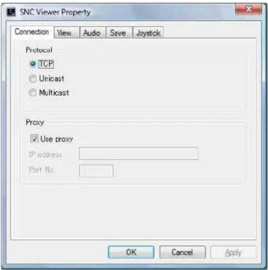
You can set the connection method.
Select the start-up connection from: TCP, Unicast, and Multicast.
If TCP connection is selected, you can configure proxy settings by selecting Use proxy.
View tab
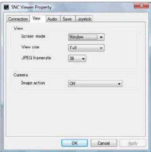
Screen mode
You can select Window or Full.
View size
You can select the view size.
JPEG framerate
You can set the frame rate for JPEG.
Image action
Select from the image operation modes Area zoom and Vector dragging.

Note
This function cannot be used with video network station.
Audio tab
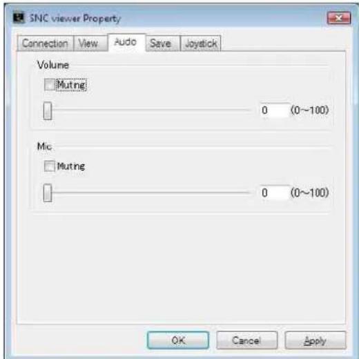
Volume
Muting: Select this option to Muting sound at start-up. Use the slide bar to set the volume for start-up sound output.
Mic
Muting: Select this option to Muting microphone sound at start-up.
Use the slide bar to set the volume for start-up microphone input.
Save tab

Specify a folder to save the still images and movies to.
Note
In the case of Windows Vista, Windows 7, Windows 8 or Windows 8.1, if "Enable Protected Mode" is checked in Control Panel-Internet Option-Security, still images cannot be shot and video content cannot be saved.
Joystick tab
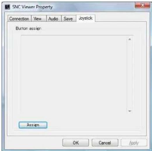
You can assign the joystick buttons here.
SNC Desktop viewer
The gadget that displays the camera image on the side bar of Windows Vista or Desktop in the case of Windows 7.
Installing the SNC desktop viewer
1 Click Download.
When the license agreement policies are displayed on the SNC desktop viewer download screen, agree after reading them carefully and download the SNC desktop viewer.
2 Click Save.
Save SncDesktopViewer.gadjet in the specified location.
3 Click Open files.
Run it in the "Download completed" dialog.
4 Click Run.
The message "Do you want to run this software?" will be displayed. Agree and run.
5 Click Install.
The message "Do you want to install this Gadget?" will be displayed. Agree and run.
Using the SNC desktop viewer
When installation is finished, SNC desktop viewer is displayed on the side bar of Windows Vista or Desktop in the case of Windows 7.
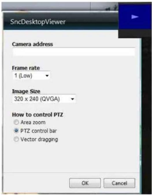
Camera address
Set the IP address for the camera to display on the Gadget.
Frame rate
Select the frame rate for the image to display on the Gadget.
Image size
Select the image size for the image to display on the Gadget.
How to control PTZ
Select the PTZ operation mode for the Gadget screen from the options Area zoom, PTZ control bar, and Vector dragging.
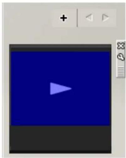
natural_image
Blue play button interface with a white triangle icon on the left (no text or symbols)Click ☑(Exit) to exit Gadget.
When you click Set), you will see the following setting screen.
Administrating the unit
This section explains how to set the functions of the unit by the Administrator.
For details about monitoring the camera image, see
"Operating the unit" on page 11.
This section explains the basic operations and each option of the Administrator menu.
Note on the display of menu options
The setting menus of this unit will clearly display only the setting options that you can currently select. Grayed out options cannot be selected.
Basic Operations of the Administrator Menu
You can use the Administrator menu to set all functions to suit the user's needs.
Click Setting in the viewer to display the Administrator menu.
How to set up the Administrator menu
1 Log in to the homepage to display the viewer. For details, see "Logging in as a user" on page 12.
2 Click Setting on the main menu. The authentication dialog appears. Enter the user name and password for Administrator. The user name “admin” and password “admin” are set at the factory for the Administrator.
The Administrator menu appears. Change the password from the factory setting for the security of your devices.
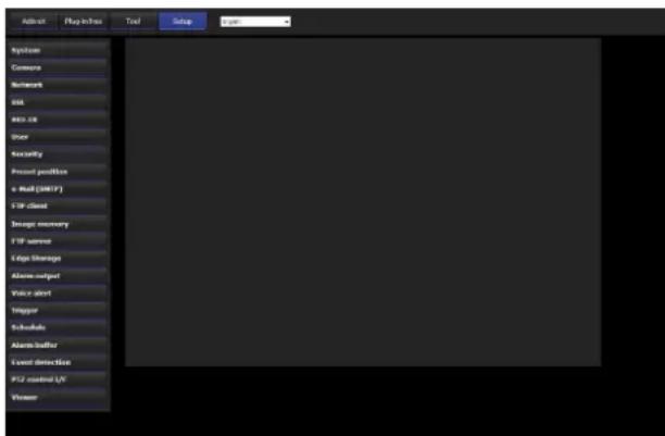
3 Click the menu name (example: System) on the left side of the Administrator menu. The clicked menu appears.
Example: "System" menu

4 Select the required tab above the menu, and set each setting option in the tab.
Example: "Date & time" tab of "System" menu

See pages 24 to 86 for details of the menu tabs and setting options.
5 After setting, click OK. The settings you have made become active.
Click Cancel to nullify the set values and return to the previous settings.
Buttons common to every menu
The following buttons are displayed on all the menus. The functions of the buttons are the same on every menu.
OK
Click this button to confirm the settings.
Cancel
Click this button to nullify the set values and return to the previous settings.
General notes on menus
- One-byte katakana character is not valid for any text field, such as User name.
- After changing a setting on a menu, wait at least 30 seconds before turning off the power of the unit. If the power is turned off immediately, the new setting may not be stored correctly.
- If the unit settings are changed while watching the main viewer, some settings cannot be restored. To reflect the change on the opening main viewer, click Refresh on the Web browser.
Configuration of the Administrator menu
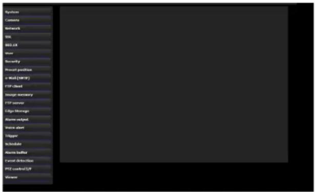
System
Displays the System menu. For details, see "Configuring the System — System Menu" (page 24).
Camera
Displays the Camera menu for setting the camera image and audio. For details, see “Setting the Camera Image and Audio — Camera Menu” (page 28).
Network
Displays the Network menu for setting the network connection. For details, see “Configuring the Network — Network Menu” (page 32).
SSL
Displays the SSL menu for performing SSL communication between the client device and system. ("Setting the SSL function — SSL Menu" on page 37)
802.1X
Displays the 802.1X menu for connecting the camera to a network configured in compliance with the 802.1X standard for port authentication. (“Using the 802.1X Authentication Function — 802.1X Menu” on page 42)
User
Displays the User menu for setting the log in user name and password. (“Setting the User — User Menu” on page 48)
Security
Displays the Security menu for specifying a computer that is allowed to connect to the camera. (“Setting the Security — Security Menu” on page 49)
Preset position
Displays the Preset position menu to register a position you want to save. “Tour function,” which rotates the registered positions, is also set here. (“Saving the Camera Position and Action — Preset position Menu” on page 51)
e-Mail (SMTP)
Displays the e-Mail (SMTP) menu for sending an e-mail. (“Sending an Image via E-mail — e-Mail (SMTP) Menu” on page 53)
FTP client
Displays the FTP client menu for sending an image/audio file, etc., to an FTP server. (“Sending Images to FTP Server — FTP client Menu” on page 57)
Image memory
Displays the Image memory menu for recording an image/audio file, etc., in the built-in memory or in a USB memory (not supplied) inserted in the unit. ("Recording Images in Memory — Image memory Menu" on page 60)
FTP server
Displays the FTP server menu for setting the FTP server function of the unit. (“Downloading Images from the system — FTP server Menu” on page 65)
Edge Storage
Set the recording of image and sound and stream them with the same protocol in Edge Storage menu. ("Setting the Edge Storage — Edge Storage Menu" on page 65)
Alarm output
Displays the Alarm output menu for setting the alarm output terminal of the unit. (“Setting the Alarm Output — Alarm output Menu” on page 67)
Voice alert
Displays the Voice alert menu for playing an audio file stored in the system in synchronization with alarm detection by the sensor input or the motion detection function. (“Outputting Audio Linked to Alarm Detection — Voice alert Menu” on page 69)
Trigger
Displays the Trigger menu for designating the operation to execute when you run a trigger. (“Setting the Operations from the Viewer — Trigger Menu” on page 70)
Schedule
Displays the Schedule menu for the Preset position function, e-Mail (SMTP) function, FTP client function, Image memory function and Alarm output function, Voice alert function, etc. (“Setting the Schedule — Schedule Menu” on page 72)
Alarm buffer
Displays the Alarm buffer menu for the buffer for storing the image and audio related to alarm detection. ("Setting the Alarm Buffer — Alarm buffer Menu" on page 73)
Event Detection
Displays the setting menu for all built-in detection functions. (“Setting the Sensor input/Camera tampering detection/Motion detection/Audio detection — Event detection menu” on page 73)
PTZ control I/F
Displays the PTZ control I/F menu for communications with external equipment through the external serial terminal. (“Transmitting with External Equipment — PTZ control I/F Menu” on page 82)
Viewer
Displays the Viewer menu from which you can select the viewer to use and configure advanced settings. ("Configuring the Viewer — Viewer Menu" on page 83)
Configuring the System — System Menu
When you click System administrator menu, the System menu appears.
Use this menu to perform the principal settings of the software.
The System menu has six tabs: System, Date & time, Superimpose, Initialize, System log and Access log.
System Tab
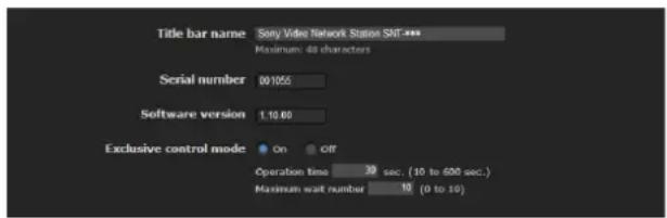
Title bar name
Type a name of up to 48 characters to be displayed on the title bar. The characters typed here are displayed on the title bar of the Web browser.
Serial number
The serial number of the camera is displayed.
Software version
The software version of this camera is displayed.
Exclusive control mode
Controls the authority to operate pan, tilt, zoom and some other functions of the camera.
Note
This operation is not available on the SNT-EP104 or SNT-EP154.
On: Only one user has control authority. Set the operation time for one user in Operation time. If a user tries to operate a function during operation by another user, the authority is controlled by the settings of Operation time and Maximum wait number.
Off: Multiple users can control pan, tilt and zoom at the same time. When multiple users control these functions at the same time, the last operation has priority.
Operation time
Sets the time length for a user who has control authority. The selectable range is from 10 to 600 seconds. This is effective when Exclusive control mode is set to On.
Maximum wait number
Sets the number of users who are permitted to wait for their turn for control authority during operation by one user. The selectable number is from 0 to 10. This is effective when Exclusive control mode is set to On.
Notes
- To use Exclusive control mode, the date and time of the system and the connected computer must be set correctly first.
- To use Exclusive control mode, do not disable the Web browser Cookie. If it is disabled, this mode cannot be used.
- When you change the Exclusive control mode setting, click Refresh on the Web browser to reflect the change when opening the main viewer page.
OK/Cancel
See "Buttons common to every menu" on page 22.
Date & time Tab

Current date & time
Displays the date and time set on the unit.
Note
After you have purchased the camera, be sure to check the date and time of the camera and set as necessary.
PC clock
Displays the date and time set on your computer.
Date & time format
Select the format of date and time to be displayed in the main viewer from the drop-down list.
You can select the format between yyyy-mm-dd hh:mm:ss (year-month-day hour:minutes:seconds), mm-dd-yyyy hh:mm:ss (month-day-year hour:minutes:seconds), and dd-mm-yyyy hh:mm:ss (day-month-year hour:minutes:seconds).
Adjust
Select how to set the day and time.
Keep current setting: Select if you do not need to set the date and time.
Synchronize with PC: Select if you want to synchronize the unit's date and time with the computer.
Manual setting: Select if you want to set the unit's date and time manually. Select the year, month, date, hour, minutes and seconds from each drop-down list.
Synchronize with NTP: Select if you want to synchronize the unit's date and time with those of the time server called NTP server (Network Time Protocol).
Set the NTP server when Synchronize with NTP is selected.
Use the following NTP server address: Synchronize with the selected NTP server address.
NTP server 1: Enter the first choice for NTP server address.
NTP server 2: Enter the second choice for NTP server address.
NTP server 3: Enter the third choice for NTP server address.
DHCP server: Select DHCP server when you need to get NTP server information from DHCP server.
Multicast: Select Multicast when you search for an NTP server with Multicast.
Time zone
Set the time difference from Greenwich Mean Time in the area where the unit is installed.
Select the time zone in the area where the unit is installed from the drop-down list.
For Japan, select "Osaka, Sapporo, Tokyo
(GMT+9:00)"
Automatically adjust the clock for daylight saving time changes
When selected, the clock is automatically adjusted according to the daylight saving time of the selected time zone.
Note
If the time zone selected in Time zone is different from that set on the computer, the time is adjusted using the time zone difference and set on the system.
OK/Cancel
See “Buttons common to every menu” on page 22.
Superimpose Tab
Select whether to superimpose the camera ID and/or date & time on the image or not.
The camera ID is also superimposed on images recorded by the Pre-alarm or Post-alarm function.
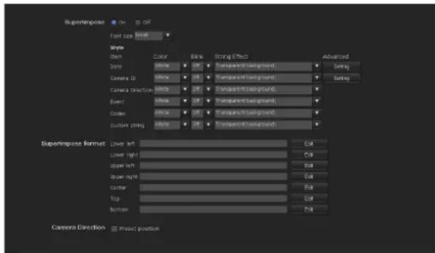
Superimpose
On/Off
When using the Superimpose function, select On.
Font size
Set the font size.
Style
Set the items to superimpose and the format to display in. English one byte characters and symbols are displayed. Superimpose settings are available for the following items:
- Date: Set the display setting for date.
- Camera ID: Configure the Camera ID display setting.
- Camera direction: set the display of a camera direction.
- Event: Configure the display setting for when an event occurs.
- Codec: Configure the bit rate and frame rate display settings display the codec of image 1.
- Custom String: Set Custom String to display the text of your choice.
Display format, including color, can be individually set for each item.
Color: Select the font color of the superimposed text.
Brink: Select On to enable brinking for the superimposed text.
String Effect: Enable a string effect for displayed text.
Advanced: Click the Setting button in Date to configure the format of date/time and the separator. In Camera ID, you can configure the Camera ID string setting and upload Superimpose Logo. Images that can be used as a Logo must be in gif89a format with an image size up to 320 × 60 . The number of pixels horizontally is even numbered and the maximum file size is approximately 50 KB. The Camera ID string and Superimpose Logo can be used exclusively.
Superimpose format
Click Edit to edit the content to superimpose over each display position.
Only one Date and one Camera ID can be specified for the Superimpose format.
You can set the content to superimpose in the bottom left, bottom right, top left, top right, center, top middle, and bottom middle parts, respectively. However, if you specify the top middle, superimposed content will not appear on the top left or top right. Similarly, if you specify bottom middle, superimposed content will not appear in the bottom left or bottom right.
Click Date & Time, Camera ID, Codec, Zoom,
Camera Direction or Event to insert the corresponding tag into the string.
Camera Direction
In the Superimpose format, select the content that will be replaced by a
Camera Direction is clicked.
Preset position
Checking here will display the preset name when the camera faces the direction registered as preset.
Note
This operation is not available on the SNT-EP104 or SNT-EP154.
OK/Cancel
See "Buttons common to every menu" on page 22.
Initialize Tab
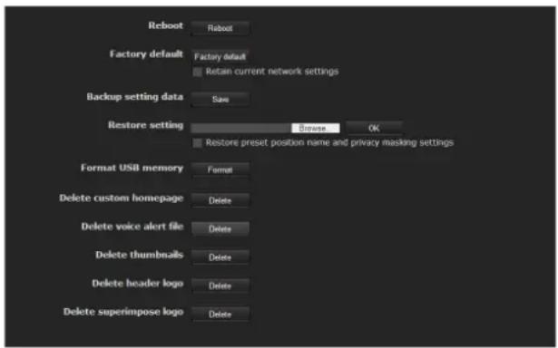
Reboot
Reboots the unit.
Click Reboot, and the message “This System will be rebooted. Are you sure?” appears. Click OK to reboot the unit.
Factory default
Resets the unit to the factory settings.
Retain current network settings
When this item is checked, only the current network settings will be retained after reset.
Click Factory default, and the message “Setup data will be initialized. Are you sure?” appears. When you click OK, the network indicator on the unit starts to blink. After adjustments of the default settings have finished, the unit reboots automatically. Do not turn off the camera until the unit reboots.
Tip
The unit can also be reset to the factory settings by turning on the power of this unit while pressing the reset button on the camera. For details, see the supplied Installation Manual.
Backup setting data
Saves the setting data of the unit in a file.
Click Save, and follow the instructions on the Web browser to specify the folder and save the setting data of the unit. The file name preset at the factory is "snt-ex104.cfg" for SNT-EX104.
Restore setting
Loads the stored setting data of the unit.
Click Browse and select the file in which the setting data is stored. Click OK, and the system is adjusted according to the loaded data, and restarted.
Restore preset position and privacy masking settings
If you select this, the stored setting data of the camera, the preset position data and the privacy masking data are loaded.
Notes
- With Restore setting, some items in the Network menu (page 32) cannot be restored.
- The following items cannot be stored or restored with Backup setting data or Restore setting.
– audio files uploaded using SNC audio upload tool - a homepage created using Custom Homepage of SNC toolbox
- a client certificate and CA certificate to be used in the 802.1X authentication function
- Header logo
– superimpose logo - a certificate to be used in the SSL function
Format USB memory
Click Format to format the USB memory inserted into the unit. The files and folders stored in the USB memory are deleted while formatting.
Notes
- Before formatting, disable the image memory function, FTP server function and Edge Storage function to protect the USB memory from writing.
- Do not activate the Format USB memory function when no USB memory is inserted into the USB connector.
- USB memory cannot be used with the SNT-EP104, SNT-EX154 and SNT-EP154.
Delete custom homepage
Click Delete to delete the homepages recorded in the flash memory of the camera with Custom Homepage of SNC toolbox.
Delete voice alert file
Click Delete to delete all the audio files stored in the camera using SNC audio upload tool (page 87).
Notes
- Clicking Delete deletes all the stored audio files simultaneously. To delete a specified audio file only, perform deletion of the audio file in the corresponding Voice alert tab of the Voice alert menu (page 69).
- Before deleting the audio file, set Voice alert to Off in each tab of the Voice alert menu (page 69).
Delete thumbnails
Click Delete to delete the thumbnails set in the Preset Setting menu.
Note
This operation is not available on the SNT-EP104 or SNT-EP154.
Delete header logo
Click Delete to delete the header logo set in the Viewer menu.
Delete superimpose logo
Click Delete to delete the superimposed logo set in the Advance of the camera ID on the Superimpose tab of the System menu.
System log Tab

The data of the software activity of the unit is recorded in this log. It includes data that is useful if a problem occurs.
Click Reload to reload the latest data.
Access log Tab
![2009-06-15 21:30:01 [102.140, 5.11] ### /com@gladnhs.txt 2009-06-15 21:30:17 [102.140, 5.11] ### /amayi 2009-06-15 21:30:15 [102.140, 5.11] ### /tom@cladnhs.txt 2009-06-15 21:30:23 [102.140, 5.11] ### /tampi 2009-06-15 21:40:15 [102.140, 5.11] ### /com@gladnhs.txt 2009-06-15 21:40:12 [102.140, 5.11] ### /amayi 2009-06-15 21:43:09 [102.140, 5.11] ### /com@gladnhs.txt 2009-06-15 21:43:08 [102.140, 5.11] ### /tampi 2009-06-15 21:43:06 [102.140, 5.11] ### /img@lab_rff.png 2009-06-15 21:43:19 [102.140, 5.11] ### /amp@lab_rff.png](/content/2026/06/1263682/images/2457d672f6036c2eeb234e649f9b9e9ab03079f66fda2274408e039db3386aa3.jpg)
The access record of the unit is displayed.
Click Reload to reload the latest data.
Setting the Camera Image and Audio
— Camera Menu
When you click Camera Administrator menu, the Camera menu appears.
Use this menu to set the functions of the camera. The Camera menu consists of five tabs: Common, Picture, Privacy masking, Video codec and Streaming.
Common Tab
Notes
- SNT-EP104 and SNT-EP154 do not have Common Tab.
- Voice alert configuration is only available for CH1 on the SNT-EX154.

Focus mode
Select the focus mode.
Auto: The focus is automatically adjusted.
Manual: The focus can be adjusted by using the 📷,
and button fresh control panel displayed in the main viewer.
Audio codec
Select whether you are going to send audio from the microphone input connector. Select On to send the audio from the system.
Notes
- When you change the Audio codec setting, click Refresh on the Web browser to reflect the change on the opening main viewer page.
- Audio codec setting, audio input setting, microphone volume setting, and audio upload are not available on the SNT-EP104 and SNT-EP154.
Audio
Select microphone input or line input.
Mic volume
When microphone input is selected, set the volume level of the audio input from the microphone input connector. It is adjustable from -10 to +10.
Codec
Select the bit rate of audio from the microphone input connector. G.711 (64kbps), G.726 (40kbps), G.726 (32kbps), G.726 (24kbps) or G.726 (16kbps) can be selected.
Note
If the bit rate is set to other than G.711(64kbps), no audio is output when you use Plug-in free Viewer.
Echo canceler
Select On to reduce echo from audio transmission.
Audio noise reduction
Select On to activate the Audio noise reduction filter.
Dynamic range compressor
Select On to activate the Dynamic range compressor.
Audio upload
Using SNC audio upload tool stored in the supplied CD-ROM, you can output audio that is input to the computer's audio input terminal from a powered speaker connected to the line output jack of the system. Select On to output audio from the speaker.
Volume
Set the speaker volume level from -10 to +10.
OK/Cancel
See "Buttons common to every menu" on page 22.
Picture Tab
You can set the color condition, brightness, etc., of the camera.
Display sample:
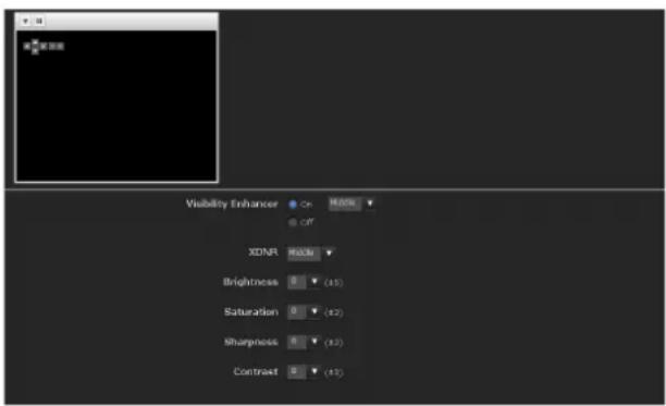
Visibility Enhancer
Using the Visibility Enhancer function makes the darker part of the camera image brighter as well as auto-adjust brightness and contrast to show bright parts clearly without white out.
To use this function, select High, Middle or Low. If you do not use this function, select Off.
XDNR
Image noise can be reduced by using the XDNR function. The intensity of the Noise Reduction filter can be selected among High, Middle and Low. If you do not use this function, select Off.
Brightness
Adjust the brightness. A larger value brightens the image, and a smaller value darkens the image. A value from -5 to +5 can be set.
Saturation
Select the saturation in 7 steps, from -3 to +3.
Selecting +3 provides the highest image saturation.
Sharpness
Select the sharpness in 7 steps, from -3 to +3.
Selecting +3 provides the sharpest picture.
Contrast
Select the contrast in 7 steps, from -3 to +3.
Selecting +3 provides the highest contrast.
OK/Cancel
See "Buttons common to every menu" on page 22.
Privacy Masking tab
Using the privacy masking enables you to hide images by masking specified parts of the images when streaming.
Note
Performing the pan/tilt/zoom operation on the camera does not change the mask position.
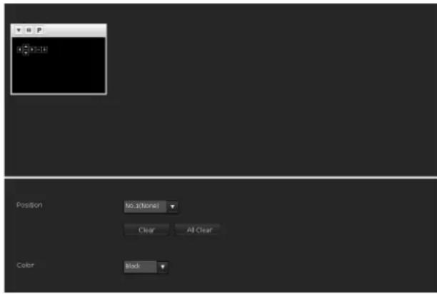
Preview screen
This screen is for monitoring images and configuring privacy masking.
For details on each button, refer to the Control bar of the Plug-in free viewer (page 16).
Control buttons
The control buttons are located at the top of the preview screen.
You can operate the camera with these buttons.
Pan/Tilt operation
Available by clicking the icon of the direction you wish to move the camera.
Zoom operation
Available by clicking - to zoom out and + to zoom in.
Position
Available to call out the privacy masks, delete them one by one or delete all at one time.
After completing the configuration, register by clicking OK.
Clear: Click the button to delete the privacy mask set.
All clear: Click the button to delete all privacy mask.
Color
Specify the color of privacy masks. This setting is common to every privacy mask.
The colors used are as follows:
Black, Gray1, Gray2, Gray3, Gray4, Gray5, Gray6,
White, Red, Green, Blue, Cyan, Yellow, Magenta
Setting a privacy mask
Operate according to the following procedure to set a privacy mask in the position of your choice:
1 Face the camera to the position where you want to set a privacy mask using the control button on the preview screen.
2 Specify the privacy mask area by dragging the mouse on the preview screen.
3 Select the number to register from the Position drop-down list.
4 Select the color of the mask from the Color drop-down list.
Note
The color is common to every privacy mask. The color selected last is applied.
5 Click OK.
The mask is displayed on the preview screen.
OK/Cancel
See "Buttons common to every menu" on page 22.
Video codec Tab
Use this tab to set the items for the video codec.
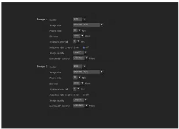
Image 1 and Image 2
Two image codec modes can be set. Configure the following setting for each image mode.
Image Codec
Select JPEG, MPEG4, H.264 or Off.
Note
The selectable size of images and frame rate for Image 2 may be limited depend on the setting of codec type, size of images and/or frame rate for Image 1.
Image size
You can select the size of the image sent from the camera.
Frame rate
Set the frame rate of the image.
“fps” is a unit indicating the number of frames transmitted per second.
Bit rate
Set the bit rate of MPEG4 or H.264 image transmission for a line. When the bit rate is set to a high level, better image quality can be enjoyed.
64, 128, 256, 384, 512, 768, 1024, 1536, 2048, 3072, 4096, 5120, 6144, 7168, 8192 (kbps)
I-Picture Interval
Set the I-picture insertion interval.
Adaptive rate control
This function adjusts the frame rate and the bit rate automatically so that the camera plays back a smooth image to suit the connected computer environment. If On is selected, the MPEG4 or H.264 image rate is automatically adjusted.
Notes
- The actual frame rate and bit rate may be different depending on the image size, shooting scene, or network condition.
- When Adaptive rate control is set to On, the maximum transmission rate will be the values set in Frame rate and Bit rate.
Image quality
Set the JPEG image quality.
Selectable values are from Level 1 to Level 10.
When Level 10 is selected, the best image quality is achieved.
Bandwidth control
Limits the network bandwidth for the JPEG image data output from the camera.
Note
Audio may be interrupted depending on the selected bandwidth. In this case, select a wider bandwidth.
OK/Cancel
See "Buttons common to every menu" on page 22.
Streaming Tab
Use this tab to set the items for the transmission by unicast or multicast.
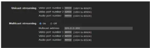
Unicast streaming
Specify the transmission port numbers of the MPEG4/H.264 video data and audio data to be used when Unicast is selected from the Connection drop-down list in the Other panel on the main viewer.
Video port number
Specify the transmission port number of the MPEG4/H.264 video data. It is initially set to 50000. Specify an even number from 1024 to 65534. Two port numbers (the number specified here and an odd number with 1 added to the specified number) are actually used for video data communication and control.
Audio port number
Specify the transmission port number of the audio data. It is initially set to 50002. Specify an even number from 1024 to 65534. Two port numbers (the number specified here and an odd number with 1 added to the specified number) are used for audio data communication and control.
Note
Specify different numbers for the video port number and the audio port number.
Multicast streaming
Set whether the unit uses multicast streaming for MPEG4/H.264 video data and audio data or not. It reduces the transmission load on the system by having a computer of the same segment network receive the same transmitting data.
Select On to allow, or Off not to allow multicast sending.
When you select On, set Multicast address, Video port number and Audio port number properly.
Multicast address
Type the multicast address used on the multicast streaming.
Video port number
Specify the MPEG4/H.264 video transmission port number used for the multicast streaming. It is initially set to 60000. Specify an even number from 1024 to 65534. Two port numbers (the number specified here and an odd number with 1 added to the specified number) are used for video data communication and control.
Audio port number
Specify the audio transmission port number used for the multicast streaming. It is initially set to 60002. Specify an even number from 1024 to 65534. Two port numbers (the number specified here and an odd number with 1 added to the specified number) are used for audio data communication and control.
Note
Specify different numbers for the video port number and the audio port number.
Configuring the Network — Network Menu
When you click Network administrator menu, the Network menu appears.
Use this menu to configure the network to connect the camera and the computer.
The Network menu consists of three tabs: Network, QoS and Dynamic IP address notification.
Network Tab
This section provides the menus for connecting the camera through the network cable.

MAC address
Displays the MAC address of the system.
Ethernet status
Displays the current transmission rate.
IPv4 setting
Configure the IPv4 network setting.
IP address
Configure the IP address.
Obtain an IP address automatically (DHCP): Select this option when a DHCP server is installed on the network to allow IP address assignment. With this setting, the IP address is assigned automatically.
Use the following IP address: Select this option when you set a fixed IP address. With this setting, specify the IP address, Subnet mask and Default gateway manually.
When you select Obtain an IP address automatically (DHCP), make sure that a DHCP server is operating on the network.
IP address
Type the IP address of the system.
Subnet mask
Type the subnet mask.
Default gateway
Type the default gateway.
DNS server
Configure the DNS server address.
Obtain DNS server address automatically: Select this option to obtain the IP address of DNS server automatically. It can be set only when Obtain an IP address automatically (DHCP) is selected in the Network tab.
Use the following DNS server address: Select this when you set a fixed address as the IP address of the DNS server. With this setting, specify the addresses on Primary DNS server and Secondary DNS server manually.
When you select Obtain DNS server address automatically, make sure that a DHCP server is operating on the network.
Primary DNS server
Type the IP address of the primary DNS server.
Secondary DNS server
Type the IP address of the secondary DNS server, if necessary.
MTU
Enter the MTU value. (1000 to 1500)
Host name
Type the host name of the system to be transmitted to the DHCP server. This setting is valid only when Obtain an IP address automatically (DHCP) is selected in the Network tab.
Domain suffix
Type the domain suffix of the system to be transmitted to the DHCP server. This setting is valid only when Obtain an IP address automatically (DHCP) is selected in the Network tab.
The domain suffix is sent to the DHCP server as FQDN (Fully Qualified Domain Name) information when Host name is set.
HTTP port number
Normally select 80. If you want to use a port number other than 80, select the text box and type a port number between 1024 and 65535.
When you have set the HTTP port number to a number other than 80 in the Network menu or in SNC toolbox, access the system again by typing the IP address of the camera on your Web browser as follows:
Example: Setting port number 8000 when IP address is 192.168.0.100
IPv6 setting
Configure the IPv6 network settings. IPv6 can be used simultaneously with IPv4. Only IPv6-specific details are explained here. For common details, see “IPv4 setting” on page 32.
On/Off
To use IPv6, select On.
Prefix
Enter the Prefix value. (0 to 128)
IPv6 MTU
Enter the MTU value. (1280 to 1500)
OK/Cancel
See "Buttons common to every menu" on page 22.
QoS Tab
In the QoS tab, traffic priority can be set by configuring the number, network address, subnet (prefix), port, protocol and/or DSCP of IPv4 or IPv6.
A maximum of 10 addresses (No.1 to No.10) can be registered.
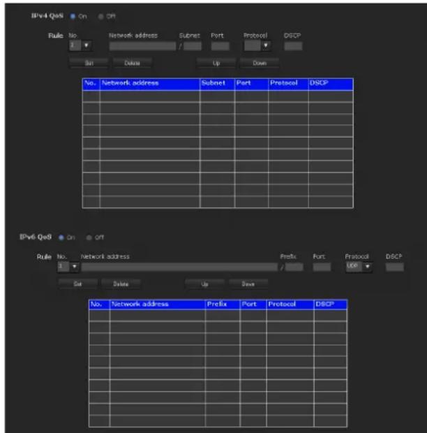
IPv4 QoS setting
Select On to configure the QoS setting for IPv4.
Rule
Used to register, edit and delete QoS.
No.
Select the number to use when registering on the QoS table.
When you select a registered number, the registered QoS information is displayed.
Network address
Enter the network address of the target on which to perform QoS.
Subnet
Enter the subnet mask values of the target on which to perform QoS.
Tip
The subnet mask value represents the number of bits from the left side of the network address.
Port
Enter the port number for the data traffic of the device (e.g. HTTP:80).
Protocol
Select the protocol.
DSCP
Set a value to mark the data traffic (0 \~ 63).
This value is set in the DSCP field included in the IP header of the data traffic.
Set
Used when registering on the QoS table.
QoS is set according to the following procedure:
1 Select No. from No. and enter the necessary conditions for Network address, Subnet, Protocol and/or Port No..
2 Enter values in DSCP.
3 Click Set and configure the QoS.
Delete
select No. to delete the setting and click Delete.
Up
Increases the priority of the rule.
Select a rule from the QoS table to prioritize and click Up.
Down
Decreases the priority of the rule.
Select a rule from the QoS table to lower its priority and click Down.
QoS table
Displays the list of registered QoS information. If multiple conditions match, the rule with the smallest number has priority.
IPv6 QoS
Select On to configure the QoS setting for IPv6.
Rule
Used to register, edit and delete QoS.
No.
Select the number to use when registering on the QoS table.
When you select a registered number, the registered QoS information is displayed.
Network address
Enter the network address of the target on which to perform QoS.
Prefix
Enter the prefix value of the target on which to perform QoS.
Tip
The prefix value represents the number of bits from the left side of the network address.
Port
Enter the port number for the data traffic of the device (e.g. HTTP:80).
Protocol
Select the protocol.
DSCP
Set a value to mark the data traffic (0 \~ 63).
This value is set in the DSCP field included in the IP header of the data traffic.
Set
Used when registering on the QoS table.
QoS is set according to the following procedure:
1 Select the number you want to register from No. and enter the necessary conditions for Network address, Subnet, Protocol and Port No..
2 Enter values in DSCP.
3 Click Set and configure the QoS.
Delete
select No. to delete the setting and click Delete.
Up
Increases the priority of the rule.
Select a rule from the QoS table to prioritize and click Up.
Down
Decreases the priority of the rule.
Select a rule from the QoS table to lower its priority and click Down.
QoS table
Displays the list of registered QoS information. If multiple conditions match, the rule with the smallest number has priority.
Tip
To attain QoS of data traffic, the target device must be connected to a router or switch that supports the QoS function.
OK/Cancel
See "Buttons common to every menu" on page 22.
Dynamic IP address notification Tab — Notifying the IP Address
When Obtain an IP address automatically (DHCP) is selected in the Network tab, you can send notification of completion of the network settings using the SMTP or HTTP protocol.
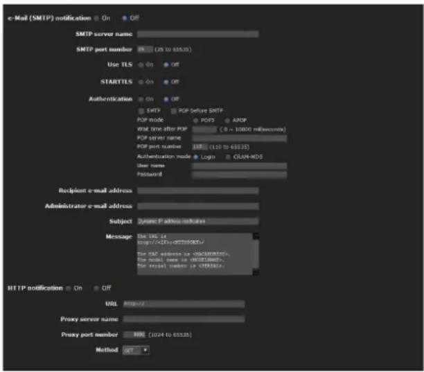
e-Mail (SMTP) notification
Select On to send an e-mail when the DHCP setting is completed.
SMTP server name
Type the name or IP address of the SMTP server for sending an e-mail, using up to 64 characters.
SMTP port number
Select the textbox and enter a port number from 25 to 65535.
Use TLS
To use the encryption function by TLS, set to On.
Note
TLS is not featured in the models to Chinese markets.
STARTTLS
To use the encryption function by STARTTLS, set to On.
Note
STARTTLS is not featured in the models to Chinese markets.
Authentication
Select the authentication required when you send an e-mail.
Off: Select if no authentication is required when an e-mail is sent.
On: Select if authentication is required when an e-mail is sent. Select one of the authentication methods from the following and specify the POP server name, User name and Password as required.
SMTP: Select when SMTP authentication is required.
POP before SMTP: Select when POP before SMTP authentication is required.
Note
When you set Authentication to On, make sure to select either or both SMTP or/and POP before SMTP.
POP mode
Select POP 3 or APOP (encrypted authentication).
Note
APOP is not featured in the models to Chinese markets.
Waiting time after POP
Set the timeout from 0 to 10000 msec.
POP server name
It is necessary when POP before SMTP is selected for Authentication.
Type the POP (receiving mail) server name, using up to 64 characters. Or type the IP address of the POP server. This setting is necessary when the SMTP server that sends e-mails performs authentication using the POP user account.
POP port number
Enter a port number from 110 to 65535.
Authentication mode
Set the user authentication mode. If you are not using CRAM-MD5, select Login.
Note
CRAM-MD5 is not featured in the models to Chinese markets.
User name, Password
Type the user name and password of the owner of the mail account, using up to 64 characters. This setting is necessary when the SMTP server that sends e-mails performs authentication.
Recipient e-mail address
Type the recipient e-mail address, using up to 64 characters. You can specify only one recipient e-mail address.
Administrator e-mail address
Type the e-mail address of the camera administrator, using up to 64 characters. This is used as the reply address or the address for a system mail from the mail server.
Subject
Type the subject/title of the e-mail, using up to 64 characters.
Message
Type the text of the e-mail using up to 384 characters. (A line break is equivalent to 2 characters.) You can describe the information of the acquired IP address, etc., using the special tags mentioned below.
HTTP notification
Select On to output a command to the HTTP server when the DHCP setting is completed. Using this function, you can configure a useful system, for example, to view the access log stored in the HTTP server, or start an external CGI program.
URL
Specify the URL to send an HTTP request, using up to 256 characters. The URL is normally written as follows:
$$ \text { http: / / ip_address[:port] / path?parameter } $$
ip_address: Type the IP address or host name of the host to which you want to connect.
To enter an IPv6 address:
http:// [IPv6 address]
http:// [IPv6 address]
[:port]: Specify the port number to which you want to connect. If you want to use the established port number 80, you do not need to input a value.
path: Type the command.
parameter: Type the command parameter if necessary. You can use the special tags mentioned below for the parameters.
Proxy server name
When you send an HTTP request via a proxy server, type the name or IP address of the proxy server, using up to 64 characters.
Proxy port number
Specify the port number when you send an HTTP request via the proxy server. Set a port number between 1024 and 65535.
Method
Select the HTTP method GET or POST.
OK/Cancel
See "Buttons common to every menu" on page 22.
About the special tags
You can use the following five special tags to allow notification of the settings acquired by DHCP, such as an IP address. Type the tags in the parameter section of the URL that you described in the Message field of the HTTP.
Use this tag to embed the IP address acquired by DHCP in the text or parameter.
Use this tag to embed the specified HTTP server port number in the text or parameters.
Use this tag to embed the MAC address of the interface, whose IP address was acquired by DHCP, in the text or parameter.
Use this tag to embed the camera's model name in the text or parameter.
Use this tag to embed the camera's serial number in the text or parameter.
Setting the SSL function — SSL Menu
When you click SSL the Administrator menu, the SSL menu appears.
Use this menu to configure the SSL or TLS function. (called "SSL" hereafter)
The settings allows the unit to communicate with the client PC by using SSL.
Notes
- The model on sale in China does not support the SSL function.
- When using the SSL function, always configure the settings after setting the date and time of the camera. If the date and time are not correctly set, it may cause browser connection problems.
SSL tab
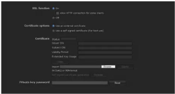
SSL function
On: Select this to use the SSL function. When Allow HTTP connection for some clients is selected, both HTTP and SSL connections are allowed. When Allow HTTP connection for some clients is not selected, only SSL connection is allowed.
When Internet Explorer is used
When SSL session is established, appears in the right of the address bar on your web browser.
Off: Select this to not use the SSL function. Only HTTP connection is allowed with the unit.
When you use SSL connection for the first time When you use SSL connection only with the SSL function On, you cannot access the unit if the SSL function does not work properly. In this case, you must reset the unit to the factory settings. (All settings will be initialized.) To avoid this, check that SSL connection is possible by performing the following steps.
1 Set the SSL function to On, and select Allow HTTP connection for some clients.
2 Click OK to close the main viewer and the setting window.
3 Display the main viewer via SSL connection. Refer to "Using the SSL function" on page 7 for connection.
4 After checking that SSL connection is possible, cancel Allow HTTP connection for some clients selected in step 1.
Even if the setting window or the browser is closed as SSL connection is impossible, http connection will be possible if Allow HTTP connection for some clients is selected. First check the setting contents of SSL tab in http connection, then check the SSL connection again.
If Allow HTTP connection for some clients is not selected, you will not be able to access the unit if SSL connection becomes impossible. In this case, turn on the power while pressing the reset switch on the unit to initialize. For details, refer to the supplied Installation Manual.
Note
SSL connection places additional burden on the unit; therefore, not all images may be downloaded, and the ✗ mark may appear when the camera accesses the setting window from the browser. In this case, reload the window. Press the F5 key on the keyboard to reload.
Certificate options
Select an installation mode of the certificate.
Use an external certificate: Uses the certificate including private key information issued by a CA. The PKCS#12 and PEM formats are supported.
Note
Even if the SSL function is set to On, it is not active in the following cases:
When Use an external certificate is selected in "Certificate options," and also when the certificate and the private key password are not set properly.
Use the camera's built-in certificate (For test use): This mode uses the certificate and private key pair generated by “Generating a self-signed certificate” on page 38. Private key information corresponding to the certificate is stored in the unit.
You do not need to install an external certificate. However, you cannot execute the existence proof that is one of the SSL functions for the following reasons.
- The private key generated by the unit is self-signed by the camera.
- A prepared value is set for a distinguished name (Common name, etc).
– The certificate is not issued by a trusted CA. For reasons of security, we recommend using this mode only when there is no problem even if perfect security is not saved.
Notes
- When Use the camera's built-in certificate (For test use) is selected, the Security Alert dialog appears on the SSL connection with a browser.
For details, refer to “Using the SSL function” (page 7). - SSL connection may be impossible due to the type of certificate installed in the unit. In this case, refer to “How to install the CA certificate” on page 40 and install.
Certificates
Import, display or delete the certificate.
To import the certificate
Click Browse... to select the certificate to be imported. Click Submit to import the selected file to the unit.
Note
The import process becomes invalid if the selected file is not a certificate or the imported certificate is not allowed.
Generating a self-signed certificate
A self-signed certificate can be generated by the unit to be used when Use the camera's built-in certificate (For test use) is selected from Certificate options.
Click Generate to generate a self-signed certificate by the unit. Clicking Generate again after Generate has been clicked once will update the self-signed certificate stored in the unit.
To display certificate information
When the certificate has been set in the unit correctly, its information appears on Status, Issuer DN, Subject DN, Validity Period and Extended Key Usage.
Status
Shows if the status of the certificate is valid or invalid. The following statuses are recognised.
Valid: The certificate is correctly stored and set.
Invalid: The certificate is not correctly stored and set. Possible causes are as follows:
- Use an external certificate is selected and the private key password included in the certificate is not specified correctly.
- Use an external certificate is selected and the private key password is specified in spite of the fact that the key pair in the certificate is not encrypted.
- Use an external certificate is selected and the key pair is not included in the certificate.
- Use the camera's built-in certificate (For test use) is selected without the self-signed certificate being generated.
Note
When the certificate to be imported is of PKCS#12 format and the private key password is not set correctly,
To delete the imported certificate or self-signed certificate
Click Delete to delete the imported certificate or self-signed certificate from the unit.
Private key password
Type the password for the private key information included in the certificate using up to 50 characters. This text box is active only when Certificate options is set to Use an external certificate.
Leave the text box blank if the private key information included in the certificate is not encrypted.
If no private key password is set in the unit, an active text field is displayed and this allows a password to be entered.
If a private key password is already set, it is displayed as an inactive text field.
Reset
To change the private key password, click this button. The current password is cleared and the password text box becomes active to allow a new password entry.
Note
Click Cancel at the bottom of the menu if you want to cancel changing the private key password after clicking Reset. Doing so restores the other setting items in the Client certificate tab to the previous settings.
OK/Cancel
See “Buttons common to every menu” on page 22.
Note
When you click OK after changing SSL setting, close the main viewer and the setting window once.
CA certificate tab — Adding the CA certificate for client authentication
In this tab, you can manage the CA certificate needed for the unit to use the client authentication of the SSL function.
Note
When using the client authentication, the personal certificate must be successfully installed on the PC to use it. If this preparation cannot be performed, do not configure settings on this tab. Otherwise, you may not be able to connect to the camera.

SSL client certificate
You can configure whether to enable the client authentication of the SSL function.
Trusted CA certificate 1 to 4
You can import a trusted CA certificate (route certificate, etc.) to the unit.
Up to four certificates from trusted CAs can be imported to the camera. Only PEM format is supported.
To import the CA certificate
1 Click Browse... to select the CA certificate to be saved in the unit.
2 Click Submit
The selected file will be imported to the unit.
Note
Import process will be invalid if the selected file is not a CA certificate.
To display the information of the CA certificate
When the CA certificate has been saved in the unit correctly, its information appears on Issuer DN, Subject DN, Validity Period, and Extended Key Usage for your reference.
To delete the CA certificate
Click Delete to delete the selected CA certificate from the unit.
Tip
To enable a client certificate, it is recommended that the settings are configured following the procedure below:
①Import the necessary CA certificate.
②Set SSL client authentication to On and click OK.
Note
When you set SSL client authentication to On and click OK, the camera will immediately operate to enable client authentication. Make sure that the personal certificate on your PC is successfully installed.
OK/Cancel
See "Buttons common to every menu" on page 22
How to install the CA certificate
The unit may not be connected because the browser (Internet Explorer) does not display whether the certificate will be accepted or not due to the type of certificate. In this case, install the CA certificate as follows.
1 On the PC, save the certificate of the CA center that signed the certificate that is to be stored in the unit. The extension of the certificate file is normally ".cer." Double-click this file. The following Certificate dialog appears.
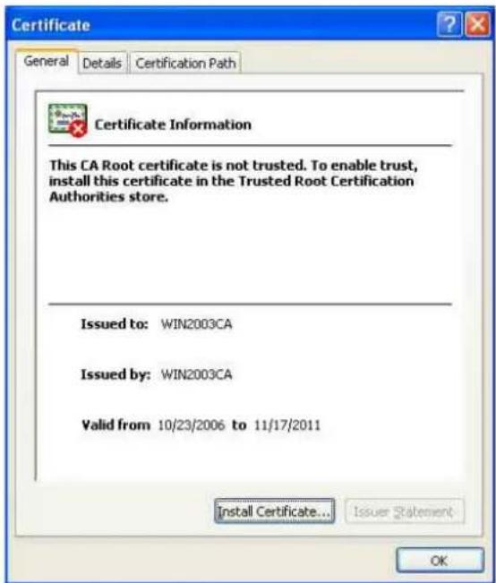
2 Click Installation Certificate.... The Certificate Import Wizard appears.

3 Click Next.
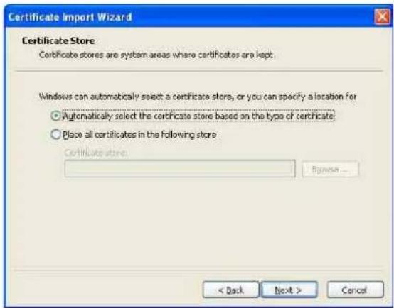
4 Select Automatically selects the certificate store based on the type of certificate and click Next. Completing the Certificate Import Wizard appears.
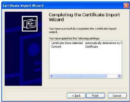
5 Check the contents, then click Finish. The CA certificate will be installed.
To remove an installed CA certificate
1 In Internet Explorer, click in the order Tools, Internet options, Content tab and Certificates. The Certificates dialog appears.
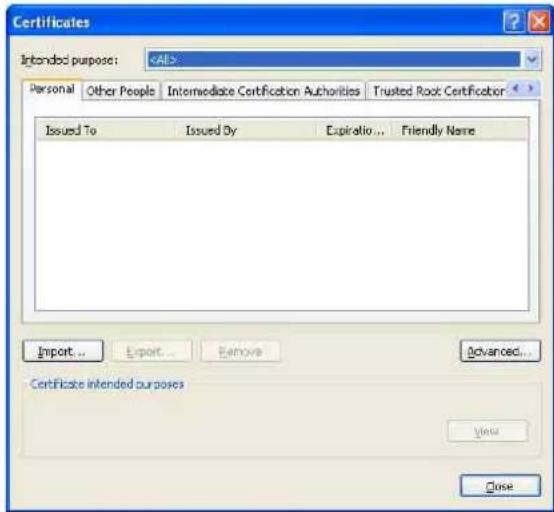
2 Select the certificate you want to remove. The CA certificate is usually stored in Trusted Root Certification Authorities.
3 Click Remove. Do you want to delete the certificate appears to confirm.
4 Click Yes The certificate will be removed. There may be a case that a certificate cannot be removed by the steps above due to the type of certificate. Check the installation condition and remove it following the steps below.
Note
You need to log in as Administrator to perform these steps.
1 Open Run... of the Windows menu, then enter mmc and click OK.
2 Select File in the Console 1 window and Add/Remove Snap-in... (when Windows XP Professional is used)
Add/Remove Snap-in... dialog appears.
3 Click Add to display Add Stand-alone Snap-in dialog.
You need to follow this step if using Windows XP Professional.

4 Select Certificates from the list, then click Add. Certificate Snap-in is displayed.
5 Select Computer account as the certificate administrated in this Snap-in, then click Next.
6 Select Local Computer as the computer administrated in this Snap-in, then click Finish.
7 Close Add Standalone Snap-in (for Windows XP Professional only) and Add/Remove Snap-in... dialogs.
The items for administrating Certificates appears in the Console Route window.
Confirm the relevant certificate, then remove it.
Using the 802.1X Authentication Function — 802.1X Menu
When you click 802.1X Administrator menu, the 802.1X menu appears.
Use this menu to configure the wired port-based authentication in compliance with the 802.1X standard. The 802.1X menu consists of three tabs: Common, Client certificate and CA certificate.
Notes
- To use the 802.1X authentication function, you need knowledge of the 802.1X authentication (WPA and WPA2) and digital certificate. To establish an 802.1X network, you need to configure the authenticator, access point, authentication server and other elements. For details on these settings, refer to the manual of the corresponding equipment.
- When using the 802.1X authentication function, always configure the settings after setting the date and time of the camera. If the date and time are incorrect, port authentication may not be performed correctly.
System configuration of 802.1X network
The following figure shows a general system configuration of an 802.1X network.

flowchart
graph TD
    A["Supplicant (video network station)"] --> B["Authenticator (hub, router or access point)"]
    B --> C["Authentication server + CA"]
Supplicant
A supplicant is a device that connects to the authentication server to join the network. This unit serves as a supplicant in the 802.1X network. The supplicant can enter the 802.1X network after appropriate authentication by the authentication server.
Authenticator
An authenticator forwards certificate request data or response data that the supplicant or authentication server issues to the other party. Normally a hub, router or access point serves as an authenticator.
Authentication server
An authentication server has a database of connecting users and verifies if the supplicant is a valid user or not. It can also be called RADIUS server.
CA (Certificate Authority)
A CA issues and manages certificates of the authentication server (CA certificates) and user certificates. The CA is essential for certificate-based user authentication. Normally a CA is located inside an authentication server.
Note
This camera supports EAP mode in which the supplicant and the server authenticate using the certificate. This mode requires a CA to issue the certificate.
Common Tab – Basic setting of 802.1X authentication function
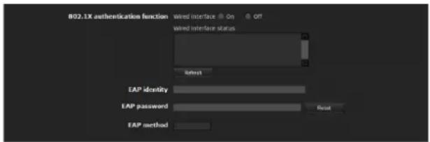
802.1X authentication function
This item is used for enabling/disabling the 802.1X authentication function for wired ports. The wired interface status and the wireless interface status can also be checked here.
Wired interface
To activate the 802.1X authentication function for wired ports, select On.
Wired interface status
Shows the authentication status of the 802.1X authentication function for wired ports.
Click Refresh to update the status.
EAP identity
Type the user name to identify the client in the 802.1X authentication server using 3 to 253 characters.
EAP password
A supplicant EAP password is needed to be inputted when PEAP is selected with EAP condition. The password can contain half-width letters and the length should be between 1 to 50.
Reset
To change the once set EAP password, click Reset and clear the current password. A new password can be entered.
Note
After you click Reset, if you wish to cancel the EAP password change, click Cancel at the bottom of the screen. This will cancel other changes made to the settings.
EAP method
You can select the authentication method used with the authentication server. This device supports TLS and PEAP.
TLS: By this method, the supplicant and the server authenticate each other using a certificate. This enables secure port authentication.
PEAP: By this method, an EAP password is used for the supplicant authentication and a certificate is used for server authentication.
OK/Cancel
See “Buttons common to every menu” on page 22.
Client certificate Tab
When TLS is selected as the EAP method, import to the unit the client certificate needed for authentication by the unit.
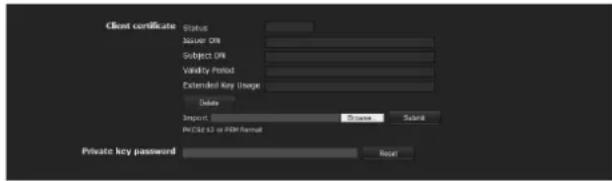
Client certificate request
Import, display or delete the client certificate.
To import the client certificate
Click Browse... to select the client certificate to be imported.
Then click Submit, and the selected file will be imported to the unit.
Note
The import process becomes invalid if the selected file is not a client certificate or the imported client certificate is not allowed.
To display the information of the client certificate
When the client certificate has been saved in the unit correctly, its information appears on Status, Issuer DN, Subject DN, Validity Period and Extended Key Usage.
Status: Shows if the status of the client certificate is valid or invalid.
Valid means the client certificate is correctly stored and set.
Invalid means the client certificate is not correctly stored and set.
Possible causes of Invalid are as follows:
- The private key password included in the client certificate is not specified correctly.
- The private key password is specified in spite of the fact that the key pair in the client certificate is not encrypted.
- The key pair is not included in the client certificate.
Note
When the client certificate to be imported is of PKCS#12 format and the private key password is not set correctly, "
Validity Period and Extended Key Usage. Specify the correct private key password to confirm the information of the certificate.
To delete the client certificate
Click Delete, and the client certificate stored in the unit will be deleted.
Private key password
Type the password for the private key information included in the client certificate using up to 50 characters.
Leave the text box blank if the private key information included in the client certificate is not encrypted.
If no private key password is set in the unit, the text box is activated to allow entering of a password.
If a private key password is already set, it is displayed as turned letters.
Reset
To change the private key password, click this button. The current password is cleared and the password text box is activated to allow new password entry.
Note
Click Cancel bottom of the menu if you want to cancel changing the private key password after clicking
Reset. Doing so restores the other setting items in the Client certificate tab to their previous settings.
OK/Cancel
See "Buttons common to every menu" on page 22.
CA certificate Tab
You can import a trusted CA certificate (server certificate or route certificate) to the unit. Up to four certificates from trusted CAs can be imported to the unit. Only the PEM format is supported.

To import the CA certificate
Click Browse... to select the CA certificate to be imported.
Then click Submit, and the selected file will be imported to the unit.
Note
Import process becomes invalid if the selected file is not a CA certificate.
To display the information of the CA certificate
When the CA certificate has been saved in the unit correctly, its information appears on Issuer DN, Subject DN, Validity Period and Extended Key Usage.
To delete the CA certificate
Click Delete, and the selected CA certificate will be deleted from the unit.
Setting the 802.1X authentication function – Example of Windows Server 2003
This section explains how to configure the authentication server and CA using Microsoft Windows Server 2003.
Note
As this section describes authentication based on the user interface in English on Windows Server 2003, the UI terminology and page configuration may be different depending on the version of the Operating System or Service Pack and patch update status.
Before setting
Perform the following settings before configuring an 802.1X network.
Active Directory (domain controller)
The following setting example is based on the assumption that the Active Directory has been configured.
Windows IAS configuration
Configure Remote access/VPN server in Manage Your Server of Windows Server 2003. Open Add or Remove Programs from Control Panel of Windows menu. Install Internet Authentication Service in Add/Remove Windows Components.
CA configuration
To configure the CA, perform the following steps:
1 Open Add or Remove Programs from Control Panel of the Windows menu.
2 Select Add/Remove Windows Components.
3 Add Certificate Services in the Component menu.
4 Select Enterprise root CA on CA Type.
5 Type the CA name on Common Name for this CA, and configure the CA.
Creating a security group for Active Directory
1 Open Active Directory Users and Computers from Administrative Tools of the Windows menu.
2 Select Users of the domain with which you want to perform 802.1X connection.
3 Select New from the context menu, then select Group and configure the group for 802.1X connection. For example, the group “Wired_802.1X_Group” is assumed for explanation purposes.
Configuring the Internet Authentication Service
1 Open Internet Authentication Service from Administrative Tools of the Windows menu.
2 Click Register Server in Active Directory on the operation menu.
3 Read the displayed precautions carefully and click OK to accept them.
Then, continue to configure the EAP-TLS policy.
4 Select Remote Access Policy and right-click.
5 Select New from the context menu, and select Remote Access Policy to open “New Remote Access Policy Wizard.”
6 Select Set up a custom policy.
7 Set the following items: Policy name: Type “Allow 802.1X Access” as an example. Policy conditions: Click Add and add the following items: - NAS Port-Type: Ethernet, Other and Virtual (VPN) - Windows-Groups: Wired_802.1X_Group Permissions: Select Grant remote access permission.
Edit Profile: - Dial-in Constraints tab: Specify the session time out period during which the client is allowed to be connected, as required. - Authentication tab: Delete checks from all the boxes. Click EAP Method and add Smart Card or other certificates.
Then, continue to configure the RADIUS client.
8 Select RADIUS Clients and right-click.
9 Select New RADIUS Client from the context menu.
10 Set the following items:
Friendly name: Type “authenticator” as an example.
Client address (IP or DNS): IP address of the authenticator
Client-Vender: RADIUS Standard
Shared secret: Specify the shared secret to be set in the authenticator.
Adding a user
1 Open Active Directory Users and Computers from Administrative Tools of Windows menu.
2 Select Users of the domain with which you want to add a user and right-click.
3 Select New from the context menu, then select User.
4 Set the following items to configure a new user: For example, the log-on user name "1XClient" is assumed for explanation purposes.
First name: 1XClient
User logon name: 1XClient@
Password: Specify a password. Then select Password never expires in account options.
5 Select the user to be added and right-click.
6 Select Properties from the context menu.
7 Set the following items:
Dial-in tab: Select Allow access in Remote Access Permission (Dial-in or VPN)
Member Of tab: Add “Wired_802.1X_Group.”
The preparations for configuring a 802.1X network are now completed. Proceed to issue the certificate to be imported to the system.
Issuing the CA certificate
Prepare a Windows client PC (called “client PC” hereafter) to temporarily store the certificate, and configure so that the client PC and Windows Server 2003 computer can be connected through the network.
1 Start Internet Explorer on the client PC.
2 Type the CA's URL in the address bar, and click Go To.
The CA's URL is normally as follows:
http://
/CertSrv/The "Microsoft Certificate Services" page opens.

Note
If the Microsoft Certificate Service page does not appear using the URL above, check the following:
– Is the service of Web site enabled on Internet Information Service (IIS)?
– Is Certificate Services enabled?
- Does the firewall or antivirus software setting on the client PC block connection?
- Are the network configuration and Internet Explorer settings on the client PC correct?
3 When Internet Explorer prompts entering the log-in user and password, type the user name as follows. Example: when the user name is "1XClient" and the domain name "localnetwork.net"
1XClient@localnetwork.net
4 Click Download a CA certificate, certificate chain, or CRL.
5 Select Base 64 in Encoding method and click Download CA certificate.
The "File Download" dialog opens.
6 Specify the file storage location and save the CA certificate.
After saving the CA certificate, import it to the system. The CA certificate import procedure is completed.
Downloading the client certificate
The procedures of the client certificate download differs depending on the TLS mode of the camera. This section explains the procedures for each mode.
When "Use a key pair from a CA" is selected
1 Start Internet Explorer on the client PC and type the CA's URL in the address bar.
The CA's URL is normally as follows:
http://
/CertSrv/2 Click Go To.
3 Type the log-in user name and password correctly. The "Microsoft Certificate Services" page opens.
4 Click Request a certificate, advanced certificate request and Create and submit a request to this CA in sequence.
5 Set the following items.
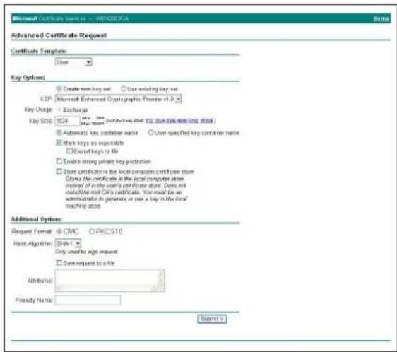
Certificate Template: User
Key Options: Create new key set
– CSP: Microsoft Enhanced Cryptographic Provider v1.0
- Key Size: 1024
- Check Mark keys as exportable.
Additional Options: Select SHA-1 for Hash Algorithm.
6 Click Submit.
The message “The certificate you requested was issued to you.” appears.
7 Click Install this certificate. to install the certificate in the certificate store on the client PC.
8 Click Internet Options, Content and Certificates of Internet Explorer in sequence.
The new client certificate is displayed in the Personal tab.
9 Select the installed certificate and click Export.... The "Certificate Export Wizard" opens.
10 Click Next and select as follows.
Do you want to export the private key with the certificate?: Select Yes, export the private key.
Select the format you want to use: Select Personal Information Exchange – PKCS#12(PFX).
Password: Specify the private key password.
File to export: Specify the name of the file to be exported.
The certificate is exported. Import the exported file to the unit as the unit's client certificate.
For details, see “To import the client certificate” in the Client certificate tab on page 44.
Setting the User — User Menu
When you click User the Administrator menu, the User menu appears.
Use this menu to set the user names and passwords of Administrator and up to 9 kinds of users (User 1 to User 9), and the access right of each user.
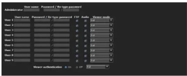
Administrator
Specify User name, Password and Re-type password.
User 1 to 9
Specify User name, Password, Re-type password, FTP, Audio and Viewer mode for each user ID.
User name
Type a user name between 5 and 16 characters.
Password
Type a password between 5 and 16 characters.
Re-type password
To confirm the password, retype the password that you typed in the Password box.
FTP
Set whether this user is allowed to log in to an FTP server or not. Check the box if the user is allowed to log in to an FTP server.
Audio
Select whether audio output to a speaker connected to the line output jack of the system is allowed or not by using the SNC audio upload tool stored in the supplied CD-ROM. Check this box to allow audio output.
Notes
- This operation is not available on the SNT-EP104 or SNT-EP154.
- Voice alert configuration is only available for CH1 on the SNT-EX154.
Note
To output audio using the SNC audio upload tool, set Audio upload to On in the Common tab of the Camera menu (page 29).
Viewer mode
When the user is authenticated for logging in the main viewer, select the viewer mode to be displayed after authentication.
Note
Pan/Tilt and Preset position are not available on the SNT-EP104 and SNT-EP154.
Full: The user can operate all functions in this mode.
Pan/Tilt: In addition to the Light mode, the user can operate pan/tilt/zoom.
Preset position: In addition to the Light mode, the user can perform the camera's preset position settings.
Light: In addition to the View mode, the user can select the image size of the main viewer, select codec and capture a still image.
View: The user can only monitor the camera image.
For the functions available for each viewer mode, see "Administrator and User" on page 11.
Viewer authentication
Set whether the user is authenticated or not when the main viewer is displayed.
Note
Pan/Tilt and Preset position are not available on the SNT-EP104 and SNT-EP154.
On: The main viewer is displayed in accordance with the viewer mode of the authenticated user.
Off: Select the viewer mode of the main viewer which is displayed without authentication from Full, Pan/Tilt, Preset position, Light or View.
OK/Cancel
See “Buttons common to every menu” on page 22.
Setting the Security — Security Menu
When you click Security administrator menu, the Security menu appears.
This allows you to control which computers can have access to the camera.
Likewise, when using IPv6, security settings can be configured for each network.
The Security menu consists of the Setting and Referer check tabs.
Setting Tab
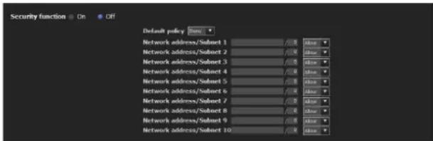
Security function
To activate the security function, select On.
Default policy
Select the basic policy of the limit from Allow and Deny for the computers specified in the Network address/Subnet 1 to Network address/Subnet 10 menus below.
Network address/Subnet 1 to Network address/Subnet 10
Type the network addresses and subnet mask values that you want to allow or deny access to the camera.
You can specify up to 10 network addresses and subnet mask values. For a subnet mask, type 8 to 32.
(In the case of IPv6, enter a value between 8 and 128.)
Select Allow or Deny from the drop-down list on the right for each network address/subnet mask.
Tip
The subnet mask value represents the bit number from the left of the network address.
For example, the subnet mask value for “255.255.255.0” is 25.
If you set 192.168.0.0/24 and Allow, you can allow access from computers having an IP address between “192.168.0.0” and “192.168.0.255.”
Note
You can access the unit even from a computer having an IP address whose access right is set to Deny, if you enter the user name and password set for the Administrator boxes in the User menu.
OK/Cancel
See "Buttons common to every menu" on page 22.
Referer check tab
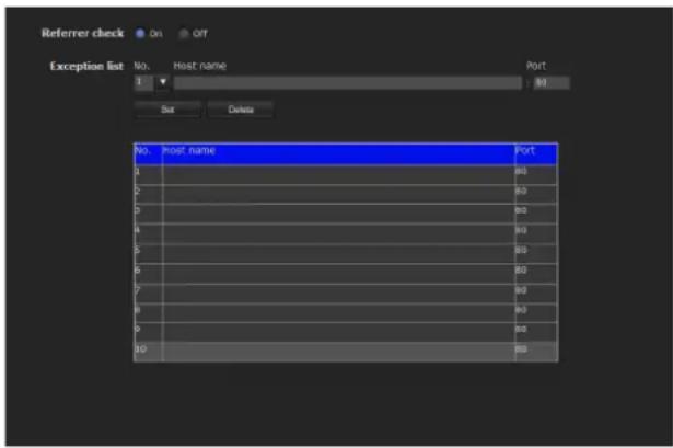
Referer check checks if the web page which requires access is authorized when the camera is accessed. If the web page is not authorized, the camera denies access of the web page to the camera.
If you want to access from web pages other than the one that the camera provides, register their host names and port numbers in the Exception list.
Referer check
Select the checkbox for the Referer check.
Exception list
Register the hosts that are not targeted for the Referer check.
No.
Select the registered numbers of the Exception list.
Host name
Type the host name or IP address of the PC that supplies the web page you want to register on the Exception list.
Port No.
Type the host name or the port number of the PC that supplies the web page you want to register on the Exception list.
Set
Register the values of the Host name and Port No. you typed to the list of the selected number.
Delete
Delete the contents of the list selected in No.
OK/Cancel
See “Buttons common to every menu” on page 22.
Saving the Camera Position and Action — Preset position Menu
When you click Preset position istrator
menu, the Preset position menu appears. This allows you to save the camera's pan, tilt and zoom positions and set position tours (programmed actions of the camera).
The Preset position menu consists of 2 tabs: Position and Tour (position).
The Preview screen is displayed in the upper part.
Position Tab — Saving pan/tilt/zoom position
You can set camera positions (pan, tilt and zoom positions).
Note
These settings are not available on the SNT-EP104 or SNT-EP154.
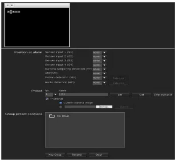
Position at alarm
The unit can synchronize a preset position with sensor input with the detection functions.
If an alarm is detected by the sensor input or the detection functions, the unit automatically moves to the corresponding preset position.
If you do not want to synchronize with any preset number, select none.
Tip
The number of selectable sensor input terminals is as follows:
SNT-EX101/SNT-EX101E: 2
SNT-EX104/SNT-EX154: 4
SNT-EP104/SNT-EP154: None
Sensor input 1 (S1)
Select a preset position to synchronize with the alarm from Sensor input 1.
Sensor input 2 (S2)
Select a preset position to synchronize with the alarm from Sensor input 2.
Sensor input 3 (S3)
Select a preset position to synchronize with the alarm from Sensor input 3.
Sensor input 4 (S4)
Select a preset position to synchronize with the alarm from Sensor input 4.
Camera tampering detection (TP)
Select the preset position to synchronize with the camera tampering detect alarm.
VMF (VM)
Select the preset position to synchronize with the VMF detection alarm.
Motion Detection (MD)
Select a preset position to synchronize with the alarm from the motion detection.
Click Detection, and the motion detection menu is displayed to allow you to set the motion detection function (page 73).
Audio detection (AD)
Select the preset position linked with alarm by audio detection function.
Click Detection, and the audio detection menu is displayed to allow you to set the audio detection function (page 73)
Note
In the case where the synchronized preset position is specified, an alarm event that happens when the camera moves to the preset position will be invalid.
Preset
You can save preset positions. You can also click Call to move the camera to a specified preset position.
No.
Select a preset number from 1 to 256 from the dropdown list.
Name
Type the preset position name of the selected preset number using up to 32 characters.
Set
Click to save the current camera position to the selected preset number.
To save a preset position, operate as follows:
1 Move the camera to the position to be saved, while checking the image with the preview viewer.
2 Select a preset number for saving, and type the preset position Name.
3 Click the Set button.
The camera position is saved.
Call
Click to move the camera to the preset position.
Clear Thumbnail
Click to delete the thumbnail of the sepecific preset position.
Thumbnail
Checking this checkbox registers a thumbnail when you register a preset position.
Select a radio button to determine whether to register the current camera image as a thumbnail or to register with a specified image.
To specify an image, click Browse. Then click Submit.
Note
JPEG format images can be used (maximum file size approximately 50 KB).
Group preset positions
You can sort preset positions into groups.
The information of the preset positions registered in a group can be viewed from the group tree screen.
By clicking the preset position in a group, the camera moves to the preset position.
New Group
You can register a new group.
Rename
You can rename the group and preset positions.
Clear
You can delete the group and preset positions.
OK/Cancel
See "Buttons common to every menu" on page 22.
Note
The OK/Cancel buttons are effective for the Position at Alarm setting in this tab.
Position Tour Tab — Setting a position tour
Positions can be programmed, and the camera can be set to move to the programmed positions sequentially (Tour).
Up to five programs can be set as Tours A to E.

Tour
Select On to enable the tour function.
Resume time on inactivity
This item becomes active when Tour is set to On.
With this item, you can select whether you restart or stop the tour after it has stopped by manual pan, tilt or zoom operation or by camera movement to the preset position triggered by an alarm.
On: Specify the wait time before the tour restarts, between 5 and 3600 seconds. The tour restarts automatically after the specified time has elapsed.
Off: The tour does not restart.
Tour A to Tour E
Configure Tour A to Tour E respectively.
Each tour setting consists of 5 items: On/Off,
Sequence, Speed, Stay time. Effective period.
Select the tour to configure from the drop-down list.
On: The tour operates.
Off: The tour does not operate.
Sequence
Set the sequence of the tour.
The preset positions saved using the Position tab are displayed in the drop-down list at the bottom.
Select the preset position from the group-tree, then click
Add. The selected preset position is added in the
Sequence list. Repeat this procedure to specify the preset positions in sequence.
You can check the preset position by clicking Call. If you specified an unnecessary preset position, click to select it in the list and then click Delete.
To change the order in the list, select the preset position and then click Up or Down.
Note
The tour cannot be set to On if no preset position is added in the Sequence list.
Stay time
Type a period of time during which the camera is to stay at each preset position, between 1 and 3600 seconds.
Effective period
Select the period during which the tour in activated.
Always: The tour can be activated any time.
Schedule: The tour is activated according to the schedule you have set.
Click Schedule, and the menu for the effective period is displayed. ("Setting the Schedule — Schedule Menu" on page 72.)
Note
You cannot set tours if the effective periods overlap each other.
OK/Cancel
See “Buttons common to every menu” on page 22.
Sending an Image via E-mail — e-Mail (SMTP) Menu
When you click e-Mail (SMTP) nistrator
menu, the e-Mail (SMTP) menu appears.
Using the e-Mail (SMTP) function, you can send an e-mail with an attached image file that has been shot linked with an external sensor input or with the built-in detection functions. An image file can also be sent periodically.
The Mail (SMTP) menu is comprised of four tabs: "Common" "Alarm sending" "Periodical sending" and "Abnormal sending."
Note
The SNT-EP104 and SNT-EP154 do not have a function to send image files from external automatic sensor inputs or linked audio detection.
Common Tab — Setting the e-Mail (SMTP) Function
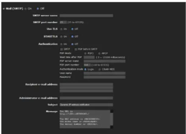
e-Mail (SMTP)
Select On when you use the e-Mail (SMTP) function.
Notes
- You cannot send an audio file by using the e-mail sending function.
- The frame rate and operability on the main viewer may be reduced while a file is being transmitted by the e-Mail (SMTP) function.
SMTP server name
Type the SMTP server name using up to 64 characters, or the IP address of the SMTP server.
SMTP port number
Select the textbox and enter a port number from 25 to 65535.
Use TLS
To use the encryption function by TLS, select On.
Note
TLS is not featured in the models to Chinese markets.
STARTTLS
To use the encryption function by STARTTLS, select On.
Note
STARTTLS is not featured in the models to Chinese markets.
Authentication
Select whether authentication is required when you send an e-mail.
Off: No authentication is required when an e-mail is sent.
On: Authentication is required when an e-mail is sent. Select one of the authentication methods from the following and specify the POP server name, User name and Password as required.
SMTP: Select when SMTP authentication is required.
POP before SMTP: Select when POP before SMTP authentication is required.
Note
When you set Authentication to On, be sure to select either or both SMTP or/and POP before SMTP.
POP mode
Select POP3 or APOP (encrypted authentication).
Note
APOP is not featured in the models to Chinese markets.
Waiting time after POP authentication
Set the timeout duration. Timeout duration can be set from 1 to 10000 msec.
POP server name
This is necessary when POP before SMTP is selected for Authentication.
Type the POP (receiving mail) server name using up to 64 characters, or type the IP address of the POP server. This setting is necessary when the SMTP server that sends e-mails performs authentication using the POP user account.
POP port number
Enter a port number from 110 to 65535.
Authentication mode
Set the user authentication mode. If you do not use CRAM-MD5, select Login.
Note
CRAM-MD5 is not featured in the models to Chinese markets.
User name, Password
Type the user name and password of the user who owns the mail account using up to 64 characters. This setting is necessary when the SMTP server that sends e-mails performs authentication.
Recipient e-mail address
Type the recipient e-mail address using up to 64 characters.
You can specify up to three recipient e-mail addresses.
Administrator e-mail address
Type the Administrator e-mail address using up to 64 characters.
This address is used for reply e-mails and sending system messages from the mail server.
Subject
Type the subject/title of the e-mail using up to 64 characters.
When Alarm sending of the Alarm sending tab is set to On, an e-mail sent in response to alarm detection will indicate the type of alarm in the subject. (S1) is added for sensor input 1 detection, (S2) for sensor input 2 detection, (S3) for sensor input 3 detection, (S4) for sensor input 4 detection, (MD) for motion detection and (AD) is additionally available for audio detection.
Message
Type the text of the e-mail using up to 384 characters. (A line break is equivalent to 2 characters.)
OK/Cancel
See “Buttons common to every menu” on page 22.
Alarm sending Tab — Setting the e-mail sending mode when detecting the alarm
Set to send an e-mail linked with alarm detection by the external sensor input or by the built-in detection functions.

Alarm sending
Select On to set sending an e-mail linked with alarm detection.
File attachment
Set whether an image file (JPEG file) is to be attached to the e-mail or not.
When On is selected, the image file made using the settings below is attached. When Off is selected, only the message is sent.
Image file name
Type the file name you want to assign to the image to be attached to an e-mail. You can use up to 10 alphanumeric characters, - (hyphen) and _ (underscore) for naming.
Suffix
Select a suffix to be added to the file name.
None: No suffix is added. The image file name is assigned to the image to be sent via e-mail.
Date & time: The date & time suffix is added to the image file name.
The date/time suffix consists of lower two-digits of the year (2 digits), month (2 digits), date (2 digits), hour (2 digits), minute (2 digits), second (2 digits), and sequential number (2 digits), thus adding 14-digit number to the image file name.
Sequence number: A sequential number of 10 digits between 0000000001 and 4294967295 and two fixed digits 00 are added to the image file name.
Sequence number clear
Click Clear to reset the Sequence number suffix to 1.
Alarm
Select the alarm to be linked with e-mail notification.
Tip
The number of selectable input terminals is as follows: SNT-EX101/SNT-EX101E: 2
SNT-EX104/SNT-EX154: 4
SNT-EP104/SNT-EP154: None *
* Alarm sending is available only for the simple motion detection function.
Sensor input 1: The external sensor that is connected to sensor input 1 of the I/O port.
Sensor input 2: The external sensor that is connected to sensor input 2 of the I/O port.
Sensor input 3: The external sensor that is connected to sensor input 3 of the I/O port.
Sensor input 4: The external sensor that is connected to sensor input 4 of the I/O port.
Tampering: An alarm that is triggered when the camera detects tampering, such as direction shift or spraying.
Interval: Set the interval at which you want to send an e-mail periodically after detection.
E-mails are sent after a specified interval time until the Camera tampering detection setting is cleared or the detection setting is turned off. You can set the hour (H) and minutes (M) between 30 minutes and 24 hours (one day).
When file attachment is set to ON, a file is only attached to an initial mail and will not be attached to the following mails.
VMF: An alarm of the VMF detection function.
Motion detection: The alarm detected by the motion detection function.
Click Detection, and the motion detection menu is displayed to allow you to set the motion detection function (page 73).
Audio detection: Select the preset position linked with alarm by audio detection function.
Click Detection, and the audio detection menu is displayed to allow you to set the audio detection function (page 73)
Note
In the case that the synchronized preset position is specified in Position at alarm in the Preset position menu, an alarm event that happens when the camera moves to the preset position will be invalid.
Effective period
Set the period during which alarm detection is effective.
Always: Alarm detection is always effective.
Schedule: You can specify the period during which alarm detection is effective.
Click Schedule and the menu for the effective period is displayed. (“Setting the Schedule — Schedule Menu” on page 72)
OK/Cancel
See “Buttons common to every menu” on page 22.
Periodical sending Tab — Setting the periodical e-mail sending mode
You can set to send e-mails periodically.
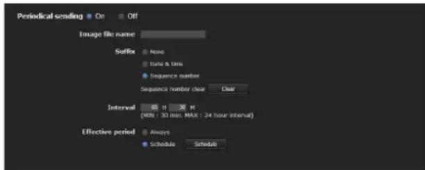
Periodical sending
Select On when you want to use periodical e-mail sending.
Image file name
Type the file name of the image attached to the e-mail using up to 10 alphanumeric characters, - (hyphen) and _ (under score).
The actual image file name will be the specified image file name with a suffix and the extension .jpg.
Suffix
Select a suffix to be added to the file name used when the e-mail is sent.
None: The name of the sent file will be the image file name.
Date & time: The date & time suffix is added to the image file name.
The date & time suffix consists of the year (2 digits), month (2 digits), date (2 digits), hour (2 digits), minutes (2 digits) and seconds (2 digits), and sequential number (2 digits), thus adding a 14-digit number to the image file name.
Sequence number: A sequential number of 10 digits between 0000000001 and 4294967295 and two fixed digits 00 are added to the image file name.
Sequence number clear
Click Clear to reset the Sequence number suffix to 1.
Interval
Type the interval at which you want to send an e-mail periodically. You can set the hour (H) and minutes (M) between 30 minutes and 24 hours (one day).
Effective period
Set the period during which periodical sending will be effective.
Always: Periodical sending is always effective.
Schedule: You can specify the period during which periodical sending is effective.
Click Schedule and the menu for the effective period is displayed. (“Setting the Schedule — Schedule Menu” on page 72)
OK/Cancel
See "Buttons common to every menu" on page 22.
Abnormal sending tab — Setting the abnormal e-mail sending mode

Abnormal sending
Select On to use abnormal sending.
Alarm
Select the alarm to be linked with e-mail notification.
Fan: Gives an alarm when the built-in fan stops. (SNT-EX154/EP154)
Video loss: Gives an alarm when video input is not available.
Resume sending
Set whether to resume periodical sending.
When it is set to on, a mail is sent every hour.
Recipient e-mail address
Type the recipient e-mail address, using up to 64 characters.
Administrator e-mail address
Type the e-mail address of the camera administrator, using up to 64 characters. This is used as the reply address or the address for a system mail from the mail server.
OK/Cancel
See "Buttons common to every menu" on page 22.
Sending Images to FTP Server
— FTP client Menu
When you click FTP client administrator menu, the FTP client menu appears.
Use this menu to set up for capturing and sending still images to an FTP server. Using the FTP client function, you can send an image and audio file that has been shot and recorded linked with the external sensor input or with the built-in detection functions to an FTP server. An image file can also be sent periodically.
The FTP client menu consists of three tabs: Common, Alarm sending and Periodical sending.
Note
The SNT-EP104 and SNT-EP154 do not have a function of FTP client linked with audio detection.
Common Tab — Setting the FTP client function
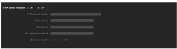
FTP client function
To activate the FTP client function, select On.
Note
The frame rate and operability on the main viewer may be reduced while a file is being transmitted by the FTP client function.
FTP server name
Type either the FTP server name to upload still images using up to 64 characters, or the IP address of the FTP server.
User name
Type the user name for the FTP server using up to 64 characters.
Password
Type the password for the FTP server using up to 64 characters.
Re-type password
To confirm the password, type the same characters as you typed in the Password box.
Passive mode
Set whether you use the passive mode of FTP server or not when connecting to the FTP server. Select On to connect to the FTP server using the passive mode.
OK/Cancel
See "Buttons common to every menu" on page 22.
Alarm sending Tab — Setting the FTP client action when detecting the alarm
Set to forward an image and audio file to a specified FTP server linked with alarm detection by the external sensor input or by the built-in detection functions.
Note
When more than two of the following settings are activated, the camera only creates two still images at the same time. A third still image cannot be created unless one of the previous two still images is sent.
e-Mail (SMTP) menu
- Alarm sending tab Alarm sending (when file attachment is set to On).
– Periodical sending Periodical sending
FTP client menu
– Alarm sending tab Alarm sending
– Periodical sending Periodical sending
Trigger menu
- Mail (SMTP)
- FTP Client

Alarm sending
Select On to send the image and audio file to the FTP server linked with alarm detection.
Remote path
Type the path to the destination using up to 64 characters.
Image file name
Type the file name you want to assign to the images when sending to the FTP server. You can use up to 10 alphanumeric characters, - (hyphen) and _ (underscore) for naming.
Suffix
Select a suffix to be added to the file name.
Date & time: The date & time suffix is added to the image file name. The date/time suffix consists of the year (2 digits), month (2 digits), date (2 digits), hour (2 digits), minute (2 digits) and second (2 digits), and sequential number (2 digits), thus adding a 14-digit number to the image file name.
Sequence number: A sequential number of 10 digits between 0000000001 and 4294967295 and a sequential 2-digit number are added to the image file name.
Tip
A sequential number added to Date & time and Sequence number is used to identify individual files created with consecutive alarm events.
Sequence number clear
Click Clear to reset the Sequence number suffix to 1.
Alarm
Select the alarm to be linked with the file to be forwarded to the FTP server.
Tip
The number of selectable input terminals is as follows: SNT-EX101/SNT-EX101E: 2 SNT-EX104/SNT-EX154: 4 SNT-EP104/SNT-EP154: None *
* Alarm sending is available only for the simple motion detection function.
Sensor input 1: The external sensor that is connected to sensor input 1 of the I/O port.
Sensor input 2: The external sensor that is connected to sensor input 2 of the I/O port.
Sensor input 3: The external sensor that is connected to sensor input 3 of the I/O port.
Sensor input 4: The external sensor that is connected to sensor input 4 of the I/O port.
Tampering: An alarm that is triggered when the camera detects tampering like direction shifting or spray.
VMF: An alarm of the VMF detection function.
Motion detection: The alarm detected by the motion detection function.
Click Detection, and the Motion detection menu is displayed to allow you to set the motion detection function (page 73).
Audio detection: Select the preset position linked with alarm by audio detection function.
Click Detection, and the audio detection menu is displayed to allow you to set the audio detection function (page 73)
Note
In the case that the synchronized preset position is specified in Position at alarm in the Preset position menu, an alarm event that happens when the camera moves to the preset position will be invalid.
Effective period
Set the period during which alarm detection is effective.
Always: Alarm detection is always effective.
Schedule: You can specify the period during which alarm detection is effective.
Click Schedule and the menu for the effective period is displayed. (“Setting the Schedule — Schedule Menu” on page 72)
Alarm buffer
Select Use alarm buffer to forward the image/audio at a specified time before or after alarm detection (pre-alarm, post-alarm).
If you do not select the alarm buffer, only the image at the moment of alarm detection is forwarded.
Click Alarm buffer to display the Alarm buffer menu.
For details, see “Setting the Alarm Buffer — Alarm buffer Menu” on page 73.
Note
When Edge Storage is enabled, the Alarm buffer is not available.
OK/Cancel
See "Buttons common to every menu" on page 22.
Periodical sending Tab — Setting the periodical FTP client activity
You can set to send image files (JPEG files) to an FTP server periodically.
Note
When more than two of the following settings are activated, the camera only creates two still images at the same time. A third still image cannot be created unless one of the previous two still images is sent.
e-Mail (SMTP) menu
- Alarm sending tab Alarm sending (when file attachment is set to On).
– Periodical sending Periodical sending
FTP client menu
– Alarm sending tab Alarm sending
– Periodical sending Periodical sending
Trigger menu
- Mail (SMTP)
- FTP Client
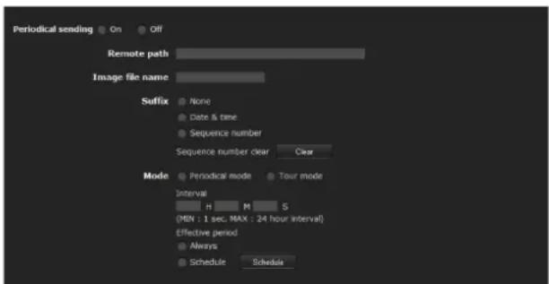
Periodical sending
Select On when you want to use periodical sending.
Remote path
Type the remote path using up to 64 characters.
Image file name
Type the file name of the image sent to the FTP server using up to 10 alphanumeric characters, - (hyphen) and _ (under score).
The actual image file name will be the specified image file name with a suffix and extension .jpg.
Note
You cannot send an audio file using periodical sending of the FTP client function.
Suffix
Select a suffix to be added to the file name sent to the FTP server.
None: The name of the sent file will be the image file name.
Date & time: The date & time suffix is added to the image file name. The date & time suffix consists of the year (2 digits), month (2 digits), date (2 digits), hour (2 digits), minute (2 digits) and second (2 digits), and sequential number (2 digits), thus adding a 14-digit number to the image file name.
Sequence number: A sequential number of 10 digits between 0000000001 and 4294967295 and two fixed digits 00 are added to the image file name.
Sequence number clear
Click Clear to reset the Sequence number suffix to 1.
Mode
Select the periodical sending mode.
Periodical mode: An image file is sent periodically according to the specified Interval and Effective period.
Tour mode: An image file is sent each time the camera is moved to a preset position during the tour.
Note
Periodical mode and Tour mode are not available on the SNT-EP104 and SNT-EP154.
Interval
Type the interval at which you want to send images to the FTP server periodically. You can set the hour (H), minutes (M) and seconds (S) between 1 second and 24 hours (one day).
Note
The actual interval may be longer than the set value, depending on the image size, image quality setting, bit rate and the network environments.
Effective period
Set the period during which periodical sending is effective.
Always: Periodical sending is always effective.
Schedule: You can specify the period during which periodical sending is effective. Click Schedule to display the menu for the effective period. (“Setting the Schedule — Schedule Menu” on page 72)
OK/Cancel
See “Buttons common to every menu” on page 22.
Recording Images in Memory — Image memory Menu
When you click Image memory istrator menu, the Image memory menu appears.
By using the image memory function, you can record an image and audio file (shot being linked with the external sensor input or built-in detection functions) in the built-in memory (approx. 8 MB), or in a USB memory (not supplied) inserted in the unit. Image files can also be recorded periodically.
The recorded image and audio files can be searched or downloaded via a computer using the FTP server function. (See “Downloading Images from the system — FTP server Menu” on page 65.)
The Image memory menu consists of three tabs:
Common, Alarm recording and Periodical recording.
Notes
- The image and audio files recorded in the built-in memory are deleted when the power of the camera is turned off, or the Selected root directory setting is changed.
- The frame rate and operability on the main viewer may be reduced during image storage.
- Set the image memory function to Off when you remove the USB memory from the camera, or when you turn off the power of the unit.
- Before using a USB memory, format it using the computer, or by Format USB memory in the Initialize tab (page 27).
- The SNT-EP104 and SNT-EP154 do not have a function of FTP client linked with audio detection.
Common Tab — Setting the image memory function

Image memory
To use the image memory function, select On.
Selected root directory
Select a memory in which you want to save an image. The current memory space is displayed on the right.
Built-in memory: Built-in memory of this unit USB memory: USB memory inserted into the unit
Notes
- The image and audio files recorded in the built-in memory are deleted when the Selected root directory setting is changed.
- When Selected root directory is set to an option other than Built-in memory, “empty” is displayed in the memory space box and you cannot access the built-in memory.
- The USB memory option is not available on the SNT-EP104, SNT-EX154 and SNT-EP154.
Overwrite
Select On to overwrite the file when there is insufficient memory space to record the image in the built-in memory or USB memory.
On: Overwrite is enabled and old files will be overwritten in the order of date.
Off: Overwrite is prohibited. No recording will be performed.
Capacity warning
Select On to send a warning mail to the Administrator when the memory space of the built-in memory or CF memory card is low or the memory is full. Select Off if you do not want to send a warning mail.
On: A warning mail is sent to the Administrator.
Off: A warning mail is not sent to the Administrator.
Note
When Overwrite is set to On, a warning mail is not sent to the Administrator.
SMTP server name
Type the name of the SMTP server for sending an e-mail, using up to 64 characters.
Otherwise type the IP address of the SMTP mail server.
SMTP port number
Select the textbox and enter a port number from 25 to 65535.
Use TLS
To use the encryption function by TLS, select On.
Note
TLS is not featured in the models to Chinese markets.
STARTTLS
To use the encryption function by STARTTLS, select On.
Note
STARTTLS is not featured in the models to Chinese markets.
Authentication
Select whether authentication is required when you send an e-mail.
Off: No authentication is required when an e-mail is sent.
On: Authentication is required when an e-mail is sent. Select one of the authentication methods from the following and specify the POP server name, User name and Password as required.
SMTP: SMTP authentication is required.
POP before SMTP: POP before SMTP authentication is required.
Note
When you set Authentication to On, be sure to select either or both SMTP or/and POP before SMTP.
POP mode
Select POP3 or APOP (encrypted authentication).
Note
APOP is not featured in the models to Chinese markets.
Waiting time after POP authentication
Set the timeout duration. Timeout duration can be set from 1 to 10000 msec.
POP server name
This is necessary when POP before SMTP is selected for Authentication.
Type a POP (receiving mail) server name using up to 64 characters, or type the IP address of the POP server. This setting is necessary when the SMTP server that sends e-mails performs authentication using the POP user account.
POP port number
Enter a port number from 110 to 65535.
Authentication mode
Set the user authentication mode.
If you do not use CRAM-MD5, select Login.
Note
CRAM-MD5 is not featured in the models to Chinese markets.
User name, Password
Type the user name and the password of the user who owns the e-mail account. This setting is necessary when the SMTP server that sends e-mails performs authentication.
Administrator e-mail address
Type the e-mail address for the recipient of a warning mail (e-mail address of the Administrator), using up to 64 characters.
OK/Cancel
See "Buttons common to every menu" on page 22.
Alarm recording Tab — Setting the Image memory function when detecting the alarm
You can set to record an image and audio file to the memory linked with an external sensor input or built-in detection functions.

Alarm recording
Select On to automatically record the image and audio files from alarm detection to the built-in memory or USB memory.
Image file name
Type the file name you want to assign to the image(s) to be recorded. You can use up to 10 alphanumeric characters, - (hyphen) and _ (underscore) for naming.
Suffix
Select a suffix to be added to the file name.
Date & time: The Date & time suffix is added to the image file name.
The Date & time suffix consists of the year (2 digits), month (2 digits), date (2 digits), hour (2 digits), minute (2 digits), second (2 digits) and sequential number (2 digits), thus adding a 14-digit number to the image file name.
Sequence number: A sequential number of 10 digits between 0000000001 and 4294967295 and an sequential 2-digit number is added to the image file name.
Tip
A sequential number added to Date & time and
Sequence number is used to identify individual files created with consecutive alarm events.
Sequence number clear
Click Clear to reset the Sequence number suffix to 1.
Alarm
Select the alarm to be linked with the recording of image and audio files.
Tip
Number of selectable input terminals is as follows:
SNT-EX101/SNT-EX101E: 2
SNT-EX104/SNT-EX154: 4
SNT-EP104/SNT-EP154: None *
* Alarm sending is available only for the simple motion detection function.
Sensor input 1: The external sensor that is connected to sensor input 1 of the I/O port.
Sensor input 2: The external sensor that is connected to sensor input 2 of the I/O port.
Sensor input 3: The external sensor that is connected to sensor input 3 of the I/O port.
Sensor input 4: The external sensor that is connected to sensor input 4 of the I/O port.
Tampering: An alarm that is triggered when the camera detects tampering, such as direction shift or spraying.
VMF: An alarm of the VMF detection function.
Motion detection: The alarm by the motion detection function.
Click Detection, and the Motion detection menu is displayed to allow you to set the motion detection function (page 73).
Audio detection: Select the preset position linked with alarm by audio detection function.
Click Detection, and the audio detection menu is displayed to allow you to set the audio detection function (page 73).
Note
In the case that the synchronized preset position is specified in Position at alarm in the Preset position menu, the alarm event that happens when the camera moves to the preset position will be invalid.
Effective period
Set the period during which alarm detection is effective.
Always: Alarm detection is always effective.
Schedule: You can specify the period during which alarm detection is effective.
Click Schedule to display the setting menu for the effective period. ("Setting the Schedule — Schedule Menu" on page 72)
Alarm buffer
Select Use alarm buffer when you record the image/audio at a specific time before or after alarm detection (pre-alarm, post-alarm).
If you do not select the alarm buffer, only the image at the moment of alarm detection is recorded.
Click Alarm buffer to display the Alarm buffer menu.
For details, see “Setting the Alarm Buffer — Alarm buffer Menu” on page 73.
Note
When Edge Storage is enabled, the Alarm buffer is not available.
OK/Cancel
See “Buttons common to every menu” on page 22.
Periodical recording Tab — Setting the periodical recording mode
You can set to record an image file (JPEG file) to the built-in memory or USB memory periodically.

Periodical recording
Select On when you want to use periodical recording.
Image file name
Type the file name of the image to be recorded to the memory using up to 10 alphanumeric characters, -(hyphen) and _ (under score).
The actual image file name will be the specified image file name with a suffix and the extension .jpg.
Note
You cannot record an audio file using the periodical recording function.
Suffix
Select a suffix to be added to the file name.
None: The recording file name will be the image file name.
Date & time: The date & time suffix is added to the image file name.
The date/time suffix consists of the year (2 digits), month (2 digits), date (2 digits), hour (2 digits), minute (2 digits), second (2 digits), and sequential number (2 digits), thus adding a 14-digit number to the image file name.
Sequence number: A sequential number of 10 digits between 0000000001 and 4294967295 and two fixed digits 00 are added to the image file name.
Sequence number clear
Click Clear to reset the Sequence number suffix to 1.
Mode
Select the periodical recording mode.
Periodical mode: An image file is recorded periodically according to the specified Interval and Effective period.
Tour mode: An image file is recorded when the camera is moved to each preset position during the tour.
Note
Periodical mode and Tour mode are not available for SNT-EP104 and SNT-EP154.
Interval
Type the interval at which you want to record an image in the memory periodically. You can set the hour (H), minutes (M) and seconds (S) between 1 second and 24 hours (one day).
Note
The actual interval may be longer than the set value depending on the image size, image quality, bit rate, or recording media.
Effective period
Set the period during which periodical recording is effective.
Always: Periodical recording is always effective.
Schedule: You can specify the period during which periodical recording is effective.
Click Schedule and the menu for the effective period is displayed. ("Setting the Schedule — Schedule Menu" on page 72)
OK/Cancel
See "Buttons common to every menu" on page 22.
Folder structure of image memory
When the image memory function is used, images are recorded with the following folder structure.
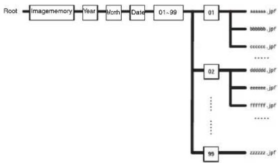
flowchart
graph TD
    Root --> Imagememory["Imagememory"]
    Imagememory --> Year["Year"]
    Year --> Month["Month"]
    Month --> Date["Date"]
    Date --> 01-99["01-99"]
    01 --> 02
    02 --> 99
    02 --> 01
    01 --> 011["...... jpf"]
    01 --> 012["...... jpf"]
    01 --> 013["...... jpf"]
    01 --> 014["......"]
    02 --> 021["...... jpf"]
    02 --> 022["...... jpf"]
    02 --> 023["......"]
    02 --> 024["......"]
    02 --> 025["......"]
    02 --> 026["......"]
    02 --> 027["......"]
    02 --> 028["......"]
    02 --> 029["......"]
    02 --> 030["......"]
    02 --> 031["......"]
    02 --> 032["......"]
    02 --> 033["......"]
    02 --> 034["......"]
    02 --> 035["......"]
    02 --> 036["......"]
    02 --> 037["......"]
    02 --> 038["......"]
    02 --> 039["......"]
    02 --> 040["......"]
    02 --> 041["......"]
    02 --> 042["......"]
    02 --> 043["......"]
    02 --> 044["......"]
    02 --> 045["......"]
    02 --> 046["......"]
    02 --> 047["......"]
    02 --> 048["......"]
    02 --> 049["......"]
    02 --> 050["......"]
    02 --> 051["......"]
    02 --> 052["......"]
    02 --> 053["......"]
    02 --> 054["......"]
    02 --> 055["......"]
    02 --> 056["......"]
    02 --> 057["......"]
    02 --> 058["......"]
    02 --> 059["......"]
    02 --> 060["......"]
    02 --> 061["......"]
    02 --> 062["......"]
    02 --> 063["......"]
    02 --> 064["......"]
    02 --> 065["......"]
    02 --> 066["......"]
    02 --> 067["......"]
    02 --> 068["......"]
    02 --> 069["......"]
    02 --> 070["......"]
    02 --> 071["......"]
    02 --> 072["......"]
    02 --> 073["......"]
    02 --> 074["......"]
    02 --> 075["......"]
    02 --> 076["......"]
    02 --> 077["......"]
    02 --> 078["......"]
    02 --> 079["......"]
    02 --> 080["......"]
    02 --> 081["......"]
    02 --> 082["......"]
    02 --> 083["......"]
    02 --> 084["......"]
    02 --> 085["......"]
    02 --> 086["......"]
    02 --> 087["......"]
    02 --> 088["......"]
    02 --> 089["......"]
    02 --> 090["......"]
    02 --> 091["......"]
    02 --> 092["......"]
    02 --> 093["......"]
    02 --> 094["......"]
    02 --> 095["......"]
    02 --> 096["......"]
    02 --> 097["......"]
    02 --> 098["......"]
    02 --> 099["......"]
A represents a folder created automatically. The Date_No. folder has an 14-digit name consisting of the year (last 2 digits), month (2 digits), day (2 digits), hour (2 digits), minute (2 digits), second (2 digits) and sequential number (2 digits).
One folder can store a maximum of 100 files. If there are more than 100 files, a new folder is created automatically to continue recording.
About the extension of a file
A file to be recorded/sent using the image memory function or the FTP client function has one of the following four extensions depending on the operation mode setting and the recording/sending settings of the unit.
.m4f: MPEG4 image files (including sound)
.jpf: JPEG image files (including sound)
.jpg: JPEG still image files
.maf: H.264 image files (including sound)
The SNC video player (page 88) allows playback of “.m4f”, “.maf” and “.jpf” files.
Downloading Images from the system — FTP server Menu
When you click FTP server ministrator menu, the FTP server menu appears. This allows you to set up for the FTP server function, which finds a specified image and audio file stored in the built-in memory (about 8 MB) or USB memory (not supplied) inserted in the camera, or downloads a file from the camera.
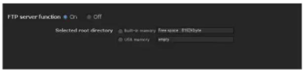
FTP server function
To activate the FTP server function, select On.
Selected root directory
Select the memory that contains the file you want to download.
The current memory space is displayed on the right.
Built-in memory: Built-in memory of this unit
USB memory: USB memory inserted into the unit
Notes
- When Selected root directory is set to an option other than Built-in memory in the Common tab of the Image memory menu, “empty” is displayed in the memory space box and you cannot access the built-in memory.
- The frame rate and operability on the main viewer may be reduced when you logged in to the FTP server of this unit using the FTP client software installed in the computer.
- USB memory cannot be used on the SNT-EP104, SNT-EX154 and SNT-EP154.
OK/Cancel
See “Buttons common to every menu” on page 22.
(SNT-EX101/EX101E/EX104 only)
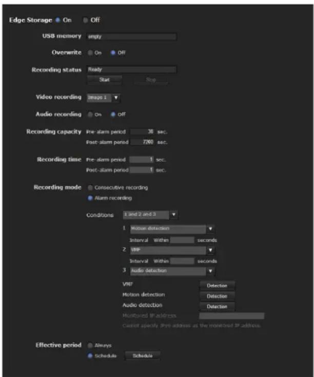
When you click Edge Storage inistrator menu, the Edge Storage menu appears.
With Edge Storage, video or audio signal can be recorded from the alarm detection results, such as network block, recorded video and audio can be streamed with the same protocol as the real-tim streaming.
Notes
- This function is only available on SNT-EX104 models with serial numbers later than 200001 and models with serial numbers later than 600001(sold in China).
- The frame rate and operability on the main viewer may be reduced during image storage.
- Stop the Edge Storage recording when you remove the USB memory from the camera or turn off the power of the camera with a USB memory inserted.
- Whenever you remove or insert a card, wait at least 10 seconds.
- Before using a USB memory, format it using the computer, or by Format USB memory in the Initialize tab of the System menu (page 27).
- The supplied ActiveX viewer is not used for streaming the recorded video or audio data. For details on supported applications, contact an authorized Sony dealer.
Edge Storage
Select On to use Edge Storage. Alarm buffer is not available when On is selected.
USB memory
Display the available free space of external USB memory.
Note
The video or audio data of Edge Storage cannot be recorded in the built-in memory.
Overwrite
Select On to overwrite the file when there is insufficient memory space to record the image in the USB memory.
On: Overwrite is enabled and old files will be overwritten in the order of date. Off: Overwrite is prohibited. No recording will be performed.
Recording status
Display the current recording status. The recording status will not be updated until the screen is refreshed. Use the Start and Stop button to start or stop the recording manually.
Video recording
Select the video codec mode you want to record. For detailed settings of video codec mode, see the Video codec tab in the camera menu.
Audio recording
Set whether to record the audio signals input from the camera. Select On to record.
Note
Audio recording is not available when the Audio codec is set to Off in the Camera Menu-Common Tab.
Recording capacity
Displays the maximum recording time of the alarm buffer in the current camera setting of the video mode, image size, bit rate and frame rate.
Note
Maximum recording time varies depending on the image size and quality setting in the Camera menu.
Recording time
Set the recording time for the Pre-alarm image/audio and Post alarm image/audio.
Pre-alarm duration
Type the recording time of the image/audio before alarm detection.
Post-alarm duration
Type the recording time of the image/audio after alarm detection.
Recording mode
Always recording: The recording is always active. Alarm recording: The recording will start when a condition as below is detected. Condition: The recording will start under the condition selected from the pull-down menu. You can select the alarm type indicated below for each number. Conditions to detect the alarm are as follows: or: detect when either condition happens. and: detect when both conditions happen within a specified interval regardless of the sequence. then: detect when each of the conditions happen within a specified interval in sequence.
Interval
Specify the interval time used when condition is set to and, then.
In the case the condition is set as 1 and 2, the system sounds an alarm when either 1 or 2 happens, and the other happens within the specified interval. In the case the condition is set as 1 then 2, the system sounds an alarm when 1 happens, and then 2 happens within the specified interval.
If you select “or” condition, this setting will be ignored. The maximum duration to be set is 7200 seconds.
Alarm to be linked with Edge Storage.
Sensor input 1: The external sensor that is connected to sensor input 1 of the camera I/O port. Sensor input 2: The external sensor that is connected to sensor input 2 of the camera I/O port. Sensor input 3: The external sensor that is connected to sensor input 3 of the camera I/O port. Sensor input 4: The external sensor that is connected to sensor input 4 of the camera I/O port. Camera tampering detection: An alarm that is triggered if the camera detects tampering, such as direction shifting or spray. VMF: An alarm of the VMF detection function. Click Detection, and the Motion detection menu is displayed to allow you to set the motion detection function (page 73).
Motion detection: The alarm detected by the motion detection function.
Click Detection, and the Motion detection menu is displayed to allow you to set the motion detection function (page 73).
Audio detection: The alarm detected by the audio detection function.
Click Detection, and the audio detection menu is displayed to allow you to set the audio detection function (page 73).
Network disconnection: The alarm detected by disconnection to a specific IP address.
IP address monitoring
Set the specific IP address of which the network connection status is to be monitored.
IP address monitoring is not available for IPv6.
Effective period
Set the effective period of Edge Storage
Always: Recording period is always effective.
Schedule: You can specify the period during which Recording period is effective.
Click Schedule and the menu to display the effective period. (“Setting the Schedule — Schedule Menu” on page 72)
OK/Cancel
See "Buttons common to every menu" on page 22.
Folder structure of Edge Storage
When the Edge Storage function is used, images are recorded with the following folder structure
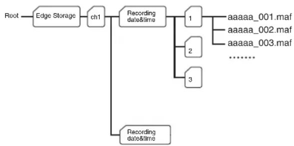
flowchart
graph TD
    A["Root"] --> B["Edge Storage"]
    B --> C["ch1"]
    C --> D["Recording date&time"]
    D --> E["1"]
    E --> F["aaaaa_001.maf"]
    E --> G["aaaaa_002.maf"]
    E --> H["aaaaa_003.maf"]
    E --> I["......"]
    D --> J["Recording date&time"]
    J --> K["2"]
    J --> L["3"]
A represents a folder created automatically. Every recording event creates a folder named with recording date and time.
Folders with maximum storage of 1,000 files are created in sequence. If more than 1,000 files recorded within one event, a new folder is created automatically to continue recording.
For the details about the extension of a file, See “About the extension of a file” on page 64.
Setting the Alarm Output — Alarm output Menu
When you click Alarm output inistrator menu, the Alarm output menu appears.
You can perform setting in this menu to control the alarm output of the I/O port on the rear of the system in conjunction with alarm detection and the timer.
The Alarm output menu consists of four tabs: Alarm output 1, Alarm output 2, Alarm output 3 and Alarm output 4.
Tips
- For details on connection of peripheral devices to the alarm output of the I/O port, refer to the supplied Installation Manual.
- The number of selectable input terminals is as follows: SNT-EX101/SNT-EX101E: 2
SNT-EX104/SNT-EX154: 4
SNT-EP104/SNT-EP154: None *
* Alarm sending is available only for the simple motion detection function.
Note
This operation is not available on the SNT-EP104 or SNT-EP154.
Alarm output Tab
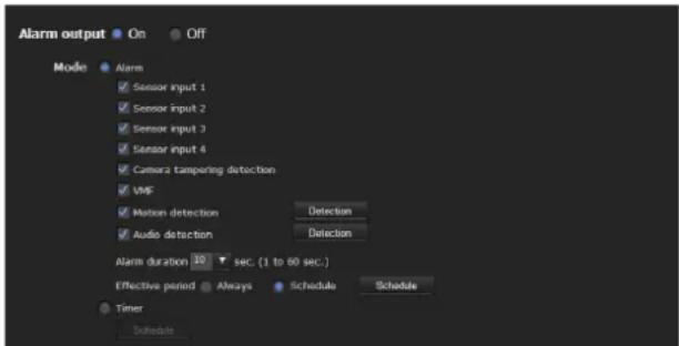
Alarm output
To activate the alarm output function, select On.
Mode
Select the mode of the alarm output function.
Alarm: Controls alarm output by synchronizing it with an external sensor input or the built-in detection functions.
When Alarm is selected, the items Sensor input 1, Sensor input 2, Sensor input 3, Sensor input 4, Tampering, VMF, Motion detection, Audio detection, Alarm duration and Effective period become active.
Timer: Controls alarm output using the timer.
Click Schedule and the menu for the effective period is displayed. (“Setting the Schedule — Schedule Menu” on page 72)
Sensor input 1
Select this option when you link the alarm output to an external sensor that is connected to sensor input 1 of the I/O port.
Sensor input 2
Select this option when you link the alarm output to an external sensor that is connected to sensor input 2 of the I/O port.
Sensor input 3
Select this option when you link the alarm output to an external sensor that is connected to sensor input 3 of the I/O port.
Sensor input 4
Select this option when you link the alarm output to an external sensor that is connected to sensor input 4 of the I/O port.
Camera tampering detect
Select this option to link the alarm output to be triggered when the camera detects tampering, such as direction shift or spraying.
VMF
Select this option when you link the alarm output to the VMF detection function.
Motion detection
Select this option when you link the alarm output to the motion detection function.
Click Detection, and the Motion detection menu is displayed to allow you to set the motion detection function (page 73).
Audio detection
Select the preset position linked with alarm by audio detection function.
Click Detection, and the audio detection menu is displayed to allow you to set the audio detection function (page 73)
Note
In the case that the synchronized preset position is specified in Position at alarm in the Preset position menu, the alarm event that happens when the camera moves to the preset position will be invalid.
Alarm duration
Select the duration for which the alarm is output, between 1 and 60 sec.
Effective period
This item becomes active when Mode is set to Alarm. Set the period during which the alarm detection is effective.
Always: Alarm detection is always effective.
Schedule: You can specify the period during which alarm detection is effective.
Click Schedule and the menu for the effective period is displayed. (“Setting the Schedule — Schedule Menu” on page 72)
OK/Cancel
See "Buttons common to every menu" on page 22.
Outputting Audio Linked to Alarm Detection
— Voice alert Menu
Click Voice administrator menu to display the Voice alert menu.
Use this menu to set the Voice alert function to output audio from the line output jack of the unit when an alarm is detected by the sensor input or detection functions. You can output audio from a speaker connected to the unit in synchronization with an alarm event triggered by the sensor input or the detection functions.
The Voice alert menu consists of 3 tabs: Voice alert 1,
Voice alert 2 and Voice alert 3. You can configure an individual audio file on each tab.
Notes
- Before using the Voice alert function, you need to save the audio file to the unit using the SNC audio upload tool stored in the supplied CD-ROM.
- For details on use of the SNC audio upload tool, see page 87.
- This operation is not available on the SNT-EP104 or SNT-EP154.
- Voice alert configuration is only available for CH1 on the SNT-EX154.
Voice alert 1, 2, 3 Tab
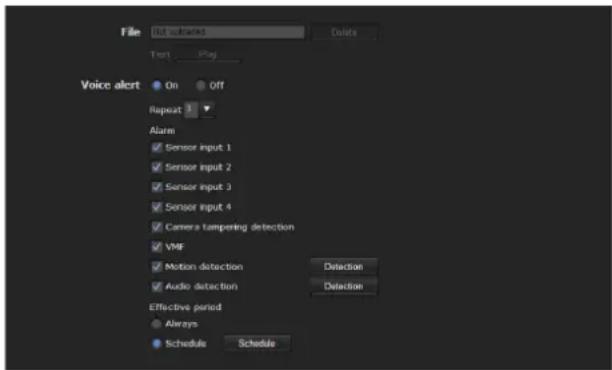
File
Displays the name of the audio file saved in the unit. "Not uploaded" is displayed dimly if no audio file is saved.
To delete the audio file saved in the unit, click Delete.
Note
Before deleting an audio file, set Voice alert to Off.
Test
When an audio file is saved in the unit, you can check it by playing it back.
Click Play to play back the audio file.
Voice alert
To use the voice alert function linked with the sensor input or the detection functions, select On.
Repeat
Select playback repeat time from 1 to 3.
Alarm
Select the alarm to be linked with the voice alert function.
Tip
The number of selectable input terminals is as follows: SNT-EX101/SNT-EX101E: 2
SNT-EX104/SNT-EX154: 4
SNT-EP104/SNT-EP154: None *
* Alarm sending is available only for the simple motion detection function.
Sensor input 1: The external sensor that is connected to sensor input 1 of the I/O port.
Sensor input 2: The external sensor that is connected to sensor input 2 of the I/O port.
Sensor input 3: The external sensor that is connected to sensor input 3 of the I/O port.
Sensor input 4: The external sensor that is connected to sensor input 4 of the I/O port.
Tampering: An alarm that is triggered when the camera detects tampering, such as direction shift or spraying.
VMF: An alarm of the VMF detection function.
Motion detection: The alarm detected by the motion detection function.
Click Detection to display Motion detection menu to allow you to set the motion detection function (page 73).
Audio detection: Select the preset position linked with alarm by audio detection function.
Click Detection, and the audio detection menu is displayed to allow you to set the audio detection function (page 73)
Notes
- If voice alert is actively linked with a different alarm event while another voice alert is occurring, the first voice alert is canceled and the second is output.
-
If two or three audio files are set to be output simultaneously linked with the same alarm event, priority is given in the order Voice alert 1, 2 then 3.
-
In the case where a preset position is specified in Position at alarm in the Preset position menu, the alarm event that occurs when the camera moves to the preset position will be invalid.
- Audio detection alarm is not triggered during playback of voice alert.
Effective period
Set the period during which alarm detection is effective.
Always: Alarm detection is always effective.
Schedule: You can specify the period during which alarm detection is effective.
Click Schedule, and the menu for the effective period is displayed. ("Setting the Schedule — Schedule Menu" on page 72)
OK/Cancel
See "Buttons common to every menu" on page 22.
Setting the Operations from the Viewer — Trigger Menu
Click Trigge Administrator menu to display the Trigger menu.
This allows you to select the activities that can be performed when the button on the Trigger panel is clicked on the main viewer.
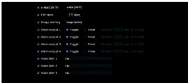
e-Mail (SMTP)
Checking this box allows you to select e-Mail (SMTP) on the Trigger panel in the main viewer.
By clicking e-Mail (SMTP) a still image of the moment you click is captured, and your e-mail with the image file attached is sent to the specified mail address.
When you click e-Mail (SMTP), the Trigger-e-Mail (SMTP) menu is displayed. You can set the necessary options here. The setting options and setting procedures are the same as those of the e-Mail (SMTP) menu (page 53).

FTP client
Checking this box allows you to select FTP client on the Trigger panel in the main viewer.
By clicking FTP client a still image of the moment you click is captured, and the image file is sent to the FTP server.
When you click FTP client, the Trigger-FTP client menu is displayed. You can set the necessary options here. The setting options and setting procedures are the same as those of the FTP client menu (page 57).
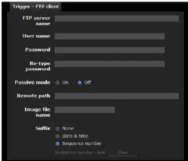
Image memory
Checking this box allows you to select Image memory on the Trigger panel in the main viewer.
By clicking Image memory a still image of the moment you click is captured, and the image file is recorded in the built-in memory or USB memory (not supplied).
Click Image memory to display the Trigger-Image memory menu. You can set the necessary options here. The setting options and setting procedures are the same as those of the Image memory menu (page 60).
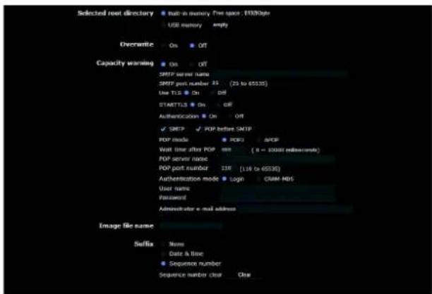
Alarm output
Checking this box allows you to select Alarm output 1, Alarm output 2, Alarm output 3 and Alarm output 4 on the Trigger panel in the main viewer. You can control the alarm output by clicking Alarm output 1, Alarm output 2, Alarm output 3 or Alarm output 4.
Note
This operation is not available on the SNT-EP104 or SNT-EP154.
Select the alarm output control mode from Toggle or Timer.
Toggle: Each time you run a trigger, On (short circuit) or Off (open) is switched.
Timer: When you run a trigger, the alarm output is switched to On, and will automatically set to Off after the time specified in Duration has elapsed.
Duration
When Timer is selected, specify the time for which the alarm output remains off, from 1 to 300 seconds.
Voice alert 1, 2, 3
Checking this box allows you to select Voice alert 1, Voice alert 2 or Voice alert 3 on the Trigger panel in the main viewer. You can output audio from the audio file saved in the system by clicking Voice alert 1, 2 or 3.
Audio file
Displays the name of the audio file saved in the system. "Not uploaded" is displayed dimly if no audio file is saved.
Notes
- This operation is not available on the SNT-EP104 or SNT-EP154.
• Voice alert configuration is only available for CH1 on the SNT-EX154.
OK/Cancel
See "Buttons common to every menu" on page 22.
Setting the Schedule — Schedule Menu
When you click Schedule administrator menu, the Schedule menu appears.
The Schedule menu consists of seven tabs.
This is the same menu as the Schedule menu that is displayed when you click Schedule to set the Effective period in the following menus.
Preset position: Schedule in the Position Tour of the Preset position menu
e-Mail: Schedule in the Alarm sending or Periodical sending tab of the e-Mail (SMTP) menu
FTP: Schedule in the Alarm sending or Periodical sending tab of the FTP client menu
Image memory: Schedule in the Alarm recording or Periodical recording tab of the Image memory menu
Alarm output: Schedule in the Alarm output 1 \~ Alarm output 4 tab of the Alarm output menu
Voice alert: Schedule in the Voice alert 1, 2 or 3 tab of the Voice alert menu
Edge Storage: the Schedule button in the setting tab from Edge Storage menu.
Note
Preset position, Voice alert and Edge Storage are not available for SNT-EP104 and SNT-EP154.
Example: When setting e-Mail (SMTP) (Periodical sending) in the Schedule menu
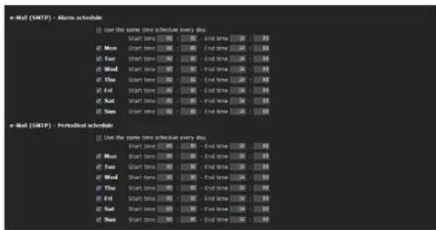
Use the same time schedule every day
When this item is checked, the same Start time and End time are applied to all days. In that case, the Start time and End time of the day from Mon (Monday) to Sun (Sunday) cannot be input.
Mon (Monday) to Sun (Sunday)
The time period on the right of the checked day is the effective period of the schedule.
Start time, End time
Specify the start time and the end time.
OK/Cancel
See "Buttons common to every menu" on page 22.
Setting the Alarm Buffer — Alarm buffer Menu
When you click Alarm administrator menu, the Alarm buffer menu appears.
You can set the Pre-alarm image and audio (the image and audio before alarm detection) and the Post -alarm image and audio. These can be set when Alarm sending of FTP client menu or Alarm recording of the Image memory menu is set to On, besides when Use alarm buffer is selected.
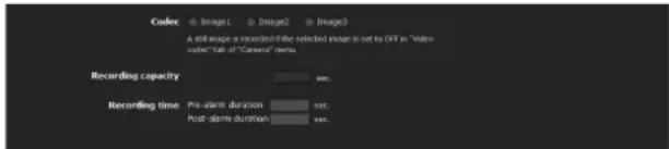
Codec
Select the video codec to be used for the alarm buffer.
Recording capacity
Displays the maximum recording capacity of the alarm buffer in the present system setting of the video mode, image size, bit rate and frame rate.
Recording time
Set the recording time for the Pre-alarm image/audio and Post alarm image/audio.
Pre-alarm duration: Type the recording time of the image/audio before alarm detection.
Post-alarm duration: Type the recording time of the image/audio after alarm detection.
Note
The value of Recording capacity differs depending on the image size and image quality settings in the Camera menu.
OK/Cancel
See "Buttons common to every menu" on page 22.
Setting the Sensor input/ Camera tampering detection/Motion detection/Audio detection
— Event detection menu
When you click Event detection in the Administrator menu, the Event detection menu appears. The Event detection menu consists of the Sensor input, Camera tampering detection, Motion detection and Audio detection tabs.
Notes
- The simple motion detection function is available for SNT-EP104 and SNT-EP154.
See “The simple motion detection function” on page 81. - Sensor input, camera tampering detection and audio detection are not available on the SNT-EP104 or SNT-EP154.
Sensor input tab — Set the sensor input
Sensor input mode
Sensor input
Normally open
Normally closed
Sensor input
Normally open
Normally closed
Sensor input
Normally open
Normally closed
School Impact
- Normally open
Normally closed

Sensor input mode
Set the direction of the detected input signal to the sensor input terminal of the camera.
Normally open: Detects the alarm when the sensor input is short-circuited.
Normally closed: Detects the alarm when the sensor input is open-circuited.
OK/Cancel
See “Buttons common to every menu” on page 22.
Camera tampering detection tab — Set the camera tampering detection
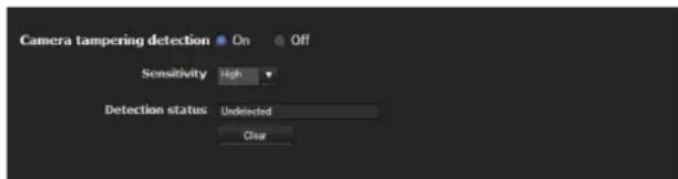
Camera tampering detection
Select On to activate the function to detect the camera tampering, such as direction shifting or spray. When you select On, you can select the Sensitivity.
Sensitivity: Set the sensitivity of camera tampering detection to High, Middle or Low.
Detection status: Display the tampering detection state of the time when Camera tampering detection tab is opened. To clear the detection status, click Clear button.
OK/Cancel
See "Buttons common to every menu" on page 22.
Motion detection tab — Set the motion/VMF detection
Motion detection detects moving objects in the camera image and outputs an alarm. In VMF, an alarm is notified when a motion detected under the motion detection setting passes, appears in, disappears from or shows any movement in a specified area or on an inspection line.
The motion detection function and the VMF function can independently set off an alarm at the time of detection.
What are VMF functions-Video Motion Filter
VMF functions are for inspecting whether a moving object detected under the motion detection settings passed, appeared in or disappeared from a specified area or inspection line.
The inspection method is selected from Pass/Presence/Appear/Disappear/Volume, and also allows for a maximum combination of three, which can be simultaneously or sequentially executed. In the VMF setting, up to three patterns can be kept for each preset for the current camera position.
Passing
A passage line is determined, and when a moving object passes the setting line, an alarm is set off.
FTP client alarm sending, image memory alarm recording and/or audio file playback can be performed in synchronization with this alarm.
Existing
When a moving object in the designated area exists after a certain period of time has elapsed, it will set off an alarm. FTP client alarm sending, image memory alarm recording and/or audio file playback can be performed in synchronization with this alarm.
Appearance
When a moving object appears in the designated area, it will set off an alarm. FTP client alarm sending, image memory alarm recording and/or audio file playback can be performed in synchronization with this alarm.
Disappearance
When a moving object disappears from the designated area, it will set off an alarm. FTP client alarm sending, image memory alarm recording and/or audio file playback can be performed in synchronization with this alarm.
Capacity
When the Capacity of moving objects in the reference area reaches definite number, an alarm is set off. FTP client alarm sending, image memory alarm recording and/or audio file playback can be performed in synchronization with this alarm.
Notes
- Before actual use, perform an operation test and confirm that the motion detection function works correctly.
- Even when privacy masking and/or cropping is used, the motion detection function operates based on the images before these functions are activated.
- When cropping is enabled, the motion detection menu is not displayed. To use the motion detection menu, disable these functions first.
When the Motion detection menu is displayed for the first time
When you click Motion detection, "Security Warning" is displayed.
When you click Yes, ActiveX control is installed and the Motion detection menu is displayed.
Notes
- If Automatic configuration is enabled in the Local Area Network (LAN) settings of Internet Explorer, the image may not be displayed. In that case, disable Automatic configuration and set the Proxy server manually. For the setting of the Proxy server, consult your network administrator.
- When you install ActiveX control, you should be logged in to the computer as Administrator.
Setting items for motion detection
Use the settings tab to set the conditions for the motion detection function while observing camera images. This menu is the same as the settings menu displayed when you click Detection on Alarm transmission on the e-Mail (SMTP) menu, or on Alarm recording on the Image memory menu.
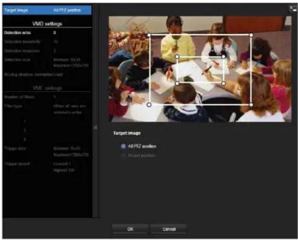
Preview screen
This screen is for monitoring images and configuring active/inactive windows.

Note
The frames shown on the monitor screen are not displayed on the image files sent or recorded with motion detection.
Target of setting
Select the camera position subject to detection settings and VMF settings from Current position or Preset. If you select Items to configure, the Current Position and Preset will be displayed. Selecting Preset will display Restore preset.
Current position: Select this option to set the current camera position as the subject of configuration.
Preset: Select this option to configure each preset. Select a preset from the list and move the camera to the preset position. The setting is enabled when the camera has moved to the set preset position.
Current position

Preset

Notes
- Camera control can be used when the mode is "Current position" mode.
- Detection settings and VMF settings should be saved independently when the and Current position and Preset is selected.
Detection settings
Detection area
Specify the effective scope of the motion detection.
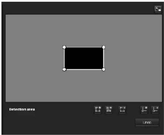
Configuring the detection area
The following procedure is used to configure the motion detection area:
1 Use the following buttons to specify the active area(s) and inactive area(s).

Adding an active area
Clicking Adding an active area will add an active area window in the center of the screen.
When you place the cursor on the area, the cursor changes to a crossed arrow, which you can drag to move the area.
When you place the cursor on the vertex of the area, the cursor changes to , which you can drag to move the vertex.

Adding an inactive area
Clicking Adding an inactive area will add an inactive area window in the center of the screen.
When you place the cursor on the area, the cursor changes to a crossed arrow, which you can drag to move the area.
When you place the cursor on the vertex of the area, the cursor changes to , which you can drag to move the vertex.

Deleting a region
Clicking Deleting a region will delete the selected active area or inactive area.
To select an area, click on the center or side of the area.

Adding a vertex
Clicking Adding a vertex will change the cursor to a button. In that state, when you click on a part of the side of the area, a vertex is added to that point. After the addition, the cursor will return to move mode.
It is the same function as the button displayed in VMF settings.

Deleting a vertex
Clicking Deleting a vertex will change the cursor to a button. In that state, when you click on a part of the side of the area, the vertex added to that point is deleted. After the deletion, the cursor will return to move mode.
It is the same function as the button displayed in VMF settings.

vertex can be moved in an outward direction cannot be moved toward the inside of an area.
Detection sensitivity
Set the sensitivity of motion detection.
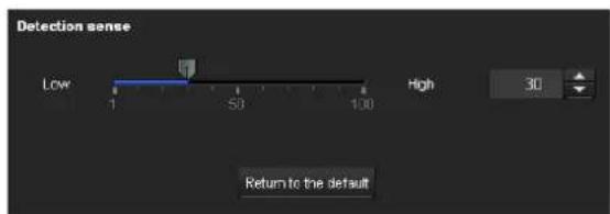
A value from 1 to 100 can be specified.
Clicking Return to the default changes the value to the default value.
Detection response
Set the response velocity of motion detection.

A value from 1 to 5 can be specified.
Clicking Return to the default changes the value to the default value.
Detection size
Specify the minimum detection size and maximum detection size of motion detection. To specify the detection size, you can either enter values or drag the vertexes of the area.
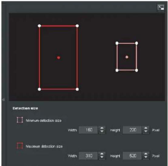
The area size is measured in pixels.
- When you place the cursor on the area, the cursor changes to a crossed arrow, which you can drag to move to the minimum detection size area and maximum detection size area.
- When you place the cursor on the vertex of the area, the cursor changes to . Drag and move the vertex to adjust the detection size.
Moving shadow exemption
Set ON/OFF for the moving shadow exemption function of the motion detection.
Selecting ON will prevent the shadows of a moving object from being recognized as moving objects.
Remove the check to disable the shadow removal function of the motion detection.
VMF setting items
Up to three VMF settings (package number1 to 3) can be retained for each current camera position and preset position. You can select one of those settings for use. You can configure the inspection method and the size and speed of object to inspect individually for each package number.
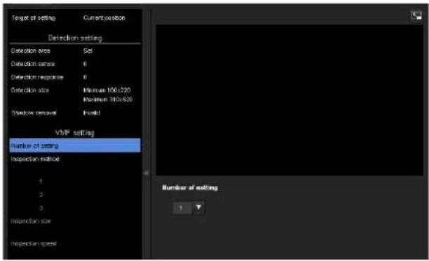
Number of filters
Select the setting number to set from 1, 2 or 3.
The following VMF setting is saved for the individual setting number selected here.
The set of the setting numbers selected here is valid for current VMF setting.
Note
package1, package2 and package3 of the VMF setting cannot be simultaneously enabled.
Filter type
Specify the VMF inspection method.

Select the inspection method from When any occur or When all occur in order.
When any occur: An alarm will be set off when any one of the three conditions is met.
When all occurs in order: An alarm will be set off when the three conditions are met in the sequence specified. If the conditions occur in an order different from the sequence specified, such as 1, 3 and then 2, there will be no alarm.
Each inspection method can include up to 3 criteria.
Select the inspection method from Pass, Presence,
Appear, Disappear, Volume and None.
Enable/Disable checkbox for filter
Set enable/disable for individual inspection methods.
Filter order switching button
Clicking switches the order of inspection methods between the neighbouring methods.
e.g., If you click the button between 1 and 2, they will switch order. If you click the button between 2 and 3, they will switch order.
Specifying the time for "When all occurs in order"
Specify the reference interval in seconds between 1 and 2, or 2 and 3.
For example, if “At least 3 seconds” is specified, the state of 2 being acknowledged two seconds after 1 has been acknowledged will not validate the acknowledgment of 2.
VMF status indicator
The indicator is on when the set filter type conditions are met.
Filter settings
Settings for each filter can be edited here.
The inspection line and active window are set to default values. Edit according to use.
VMF status indicator of each filter
The filter is on when the set filter type conditions
(Passing, Existing, Appearance, Disappearance,
Capacity) are met.
Tip
The buttons displayed on the edit screen for inspection method is used in the same way as those for detection setting. See page 76.
Passing

Edit the pass inspection line according to the following procedure:
Passing object trigger line
By default, one passing object trigger line is displayed. The number of vertexes is 2.
Placing the cursor on the line will turn the cursor into a cross, and when you drag the line, the whole line will move.
Placing the cursor on the vertex will turn the cursor into
↔, and when you drag the line, the vertex will move. The arrow displayed in the center of the passing object trigger line shows the direction of inspection. trigger is performed when an object passes the passing object trigger position in this direction.
Trigger direction setting
Each time you click the trigger direction toggles among the directions left, right and both.
Passing object trigger position
Select the passing object trigger position from Center, Left side, Top side, Right side and Bottom side.
Existing

Similar to a active window an trigger area can also be moved and vertexes can be moved/added or deleted. If an object exists within the window longer than the specified time, existing is acknowledged.
Duration
Specify the time of existing.
Appearance
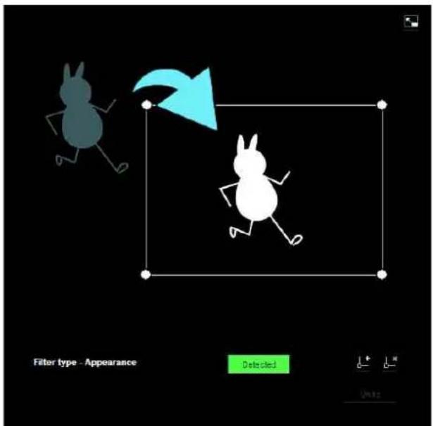
This criterion is whether an object appeared in the trigger area.
Similar to an active window, a trigger area can also be moved and vertexes can be moved/added or deleted.
Disappearance

This criterion is whether an object disappeared in the trigger area.
Similar to an active window, a trigger area can also be moved and vertexes can be moved/added or deleted.
Capacity
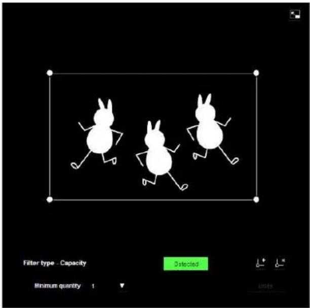
This criterion is the number of objects found in the trigger area.
The quantity is specified from the pull-down list.
Similar to a active window, the trigger area can also be moved and its vertexes can also be moved, added or deleted.
Minimum quantity: The quantity is specified from the "Minimum quantity" pull-down.
Trigger size
Specify the minimum trigger size and maximum trigger size of the object. To specify the size, you can either enter values or drag the vertexes of the area.
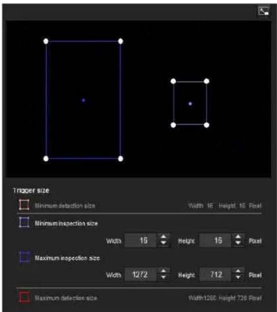
The size of an object is measured in pixels.
- When you place the cursor on the area, the cursor changes to a crossed arrow, which you can drag to move the minimum trigger size area and maximum trigger size area.
- Placing the cursor on the vertex of the minimum trigger size area or maximum trigger size area will change the cursor to , then you can drag the vertex to change the inspection size.
Tip
The minimum and maximum detection sizes configured in the VMD setting are displayed, but the size of the area cannot be modified from here.
Trigger speed
Specify the range of the speed of object to inspect by determining Min. speed and Max. speed.
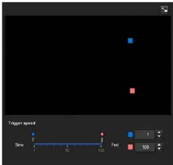
- Min. speed and Max. speed can be specified within a scale of 100.
- The blue marker for minimum speed cannot be set to the right of the red marker for maximum speed.
- The squares indicating Min. speed and Max. speed move on the right and left sides of the preview screen.
Note
The set value is only valid under the conditions of Passing, Appearance or Disappearance.
Full-screen display button
Click 📄 to display the ActiveX area in full screen. Clicking again will show the normal display.
Stretch bar
Click hide the menu list on the left and enlarge the preview screen. Clicking again will show the menu list as it was before.
OK/Cancel
Click OK to finalize any changes made to the settings and send them to the camera.
If you click Cancel, changes made to the settings will be discarded and the screen will be reloaded with the current camera settings.
Simple motion detection function
The following three simple functions are provided for motion detection. The simple motion detection function is available on the SNT-EP104 and SNT-EP154.
Detection level
Set the sensitivity of the motion detection. Set a scale from [1] to [100].
Detection size
Specify the size of moving object to be detected, from three options: Large, Medium and Small.
Motion level
If a moving object is shown in full screen, you can set the degree of motion of the object to within a scale: 1 - 100 Check the current degree of motion on the level meter and set the detection level referencing that value.
Note
VMF configuration is not available when the simple motion detection function is activated.
Audio detection tab — Set the audio detection
Audio detection detects sound picked up by a microphone, and outputs an alarm beyond a certain threshold.
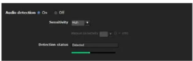
Audio detection
Select On to activate the function and set the sensitivity.
Sensitivity
Set the Sensitivity to Low, High or Manual. If Manual is selected, you may set the sensitivity manually.
Manual sensitivity
Set the Manual sensitivity from 1 to 100, the larger the number, the greater the sensitivity.
Detection status: When Audio detection is set to On in the Audio detection tab, the detection status is displayed.
If excessive sound is picked up by the microphone, "Detected" appears; otherwise "Non-detected" is displayed. The input volume is indicated in a bar that helps you to calibrate detection levels.
Notes
- Audio detection is not available on the SNT-EP104 or SNT-EP154.
- For the SNT-EX154, audio detection is only available for CH1.
- Test audio detection to confirm that it is functioning as desired.
- The audio detection function sets the detection level automatically according to the statistical samples of input volume and the sensitivity. Thus, the detection level may differ even with the same sensitivity.
- The detection of input volume cannot be updated when the Audio detection tab is open. This means at this time the detection level is not adjusted automatically according to the input sound. According to the characteristics, test audio detection when the Audio detection tab is open.
- Before setting sensitivity, in order to optimize detection, place the microphone in an ordinary location and sound environment for about 3 minutes before opening the Audio detection tab.
- The Audio detection alarm is off during playback of audio files.
- The Audio detection alarm is off while uploading audio (from a computer).
OK/Cancel
See “Buttons common to every menu” on page 22.
Transmitting with External Equipment
— PTZ control I/F Menu
When you click PTZ control I/F histrator menu, the PTZ control I/F menu is displayed.
Using this menu, you can input data into the system from the computer via a network and output them to the external serial interface to control a peripheral device.
You can also input data from a peripheral device via an external serial interface and output them to the computer via a network.
Notes
- For the SNT-EX104 and SNT-EX154, set the four video channels to the same setting, except for the camera ID, which should differ between channels. setting.
- This operation is not available on the SNT-EP104 or SNT-EP154.
Display sample: SNT-EX101
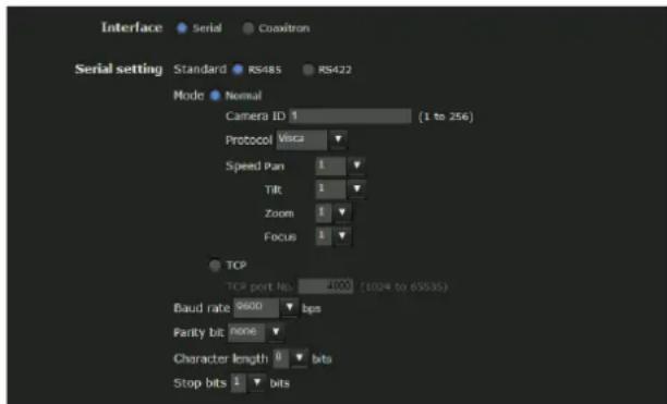
Interface
Select Coaxitron or Serial.
Serial setting
Standard
Select RS-485 or RS-422.
Note
RS-422 is only available on the SNT-EX101/SNT-EX101E.
Mode
Select the data transmission/reception method: Network (TCP) port, or Normal for the camera connection to this unit. Select Normal when not using TCP.
[Normal]: Operate the camera connected to this unit.
When Normal is selected, you can enter the camera ID for the connected camera and the protocol and operation speed.
Camera ID
Configure the Camera ID for the connected camera.
Camera Operation Protocol
[Pelco-D]: Pelco-D protocol.
[AD]: AD protocol.
[Pelco-P]: Peloc-P protocol.
[Bosch]: Bosch protocol.
[Vicon]: Vicon protocol.
[Panasonic]: Panasonic protocol.
[GE]: GE protocol.
[VISCA]: VISCA protocol.
Speed
Configure the default operation speed when operating the camera connected to this unit. If operation speed is set outside a protocol's specified range, performance will depend on the connected camera.
Pan
Configure the pan operation speed for the connected camera.
Tilt
Configure the tilt operation speed for the connected camera.
Zoom
Configure the zoom operation speed for the connected camera.
Focus
Configure the focus operation speed for the connected camera.
[TCP]: Use the TCP port to input and output data through the external serial interface.
When TCP is selected, you can enter the TCP port No.
TCP port number
Enter the port number for the data transmission/reception. Specify a port number (1024 to 65535) that is not commonly used.
Baud rate
Select a baud rate that corresponds to the peripheral device of serial interface. You can select one of the following baud rates:
38400, 19200, 9600, 4800, 2400, 1200 (bps)
Parity bit
Select a parity (none, odd or even) that corresponds to the peripheral device connected to the serial interface.
Character length
Select a character length (7 or 8 bits) that corresponds to the peripheral device connected to the serial interface.
Stop bits
Select a stop bit setting (1 or 2 bits) that corresponds to the peripheral device connected to the serial interface.
OK/Cancel
See "Buttons common to every menu" on page 22.
Configuring the Viewer — Viewer Menu
Click Viewe Administrator menu to display the Viewer menu.
Using this menu, you can select the viewer to use and configure advanced settings.
Layout tab
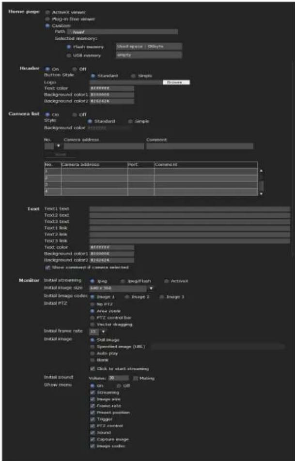
Homepage
Set the viewer or homepage to be displayed at the time of access.
ActiveX Viewer: Displays the ActiveX viewer at time of access.
Plug-in free Viewer: Displays the Plug-in free viewer at time of access.
Custom: Select the homepage to be displayed. You can display your favorite homepage stored in the built-in flash memory or USB memory (not supplied).
To store a homepage HTML file in the built-in flash memory, use the Custom Homepage function of SNC toolbox included in the supplied CD-ROM.
To display your Custom homepage perform the following operation:
1 Select Custom.
2 Type the path of the HTML file using up to 64 characters in the text box on the right of Path.
3 In Selected memory, you can select either Flash memory or USB memory in which the homepage is stored.
The directory displayed in the text box on the right of Path changes according to the selected memory.
Header
Configure the setting for the bar menu displayed at the top of the viewer screen. Select On to display the header, and Off to hide it.
Tip
Even when you select Custom, the homepage inside the camera can be displayed by typing the following URL in the address box of your Web browser.
Example: When the IP address of the camera is set to 192.168.0.100
http://192.168.0.100/en/index.html
Enter the following value to
en : English
ja : Japanese
fr : French
de : German
it : Italian
es : Spanish
zh_hant : Chinese (Traditional Chinese character)
zh_hans : Chinese (Simplified Chinese character)
ko : Korean
Button style
Select Standard or Simple.
Logo
To set the logo image, click Browse and specify the image to display. The image file format that can be used is GIF, PNG, JPEG. The maximum file size is 50KB. The uploaded image is displayed as 150 × 48 pixel. Click Delete header logo to delete the log set on the Initialize Tab of system menu (page 28).
Text color, Background color 1, and Background color 2
Specify the background colors and font color. To specify the color, enter “#” followed by an RGB value in 6-digit hexadecimal.
The first 2 digits after # represent red, the next 2 digits green, and the last 2 digits blue. Specify the brightness for each color. 256 brightness levels are available (00-FF).
Camera list
You can register cameras in the camera list. By selecting a registered camera on the viewer screen, you can see the images from the registered camera.
Note
The camera list can be set only when Plug-in free Viewer is selected as the homepage.
On/Off
Select On to show the camera list, and Off to hide it.
Style
You can configure the camera list style.
Background color
Specify the background color of the camera list. The colors are specified in the same way as those for the header.
Registering in Cameras
Specify a number on the camera list and set the IP address, port number, and comment for each camera.
Insert: Click to register a camera in the camera list.
Modify: Click to edit a selected camera list.
Delete: Click to delete a selected camera list.
Down: Click to decrement the number indicating registered camera numbers.
Up: Click to increment the number indicating registered camera numbers.
Text
Note
The camera list can be set only when Plug-in free Viewer is selected as the homepage.
Text1 text, Text2 text and Text3 text
Enter the text to be displayed on the viewer screen.
Text1 link, Text2 link and Text3 link
Specify the URL of the link to assign a link to the text.
Text color, background color 1, and background color 2
Specify the font color of the text and background colors. The colors are specified in the same way as specifying those for the header.
Display comment when camera is selected
Select this option to display comments on the viewer screen.
Monitor
Configure the setting for the camera image display part of Plug-in free Viewer.
Note
The camera list can be set only when Plug-in free Viewer is selected as the homepage.
Initial streaming
Set the display method for camera images.
Initial image size
Set the initial camera image size.
Initial image codec
Set the initial codec mode.
Image 1: Display the image set in the Image 1 of camera menu-video codec tab when streaming starts.
Image 2: Display the image set in the Image 2 of camera menu-video codec tab when streaming starts.
Image 3: Display the image set in the Image 3 of camera menu-video codec tab when streaming starts.
Note
Image 1 is automatically displayed on the monitor screen if the selected camera from the Camera list is as follows:
- Image2: Codec of Image 2: Off.
- Image3: Image 3 function is not installed, or Codec of Image 3: Off.
You can check the settings for codec in Camera menu-
Video codec tab.
Initial PTZ
Set the pan/tilt/zoom operation modes of the camera.
No PTZ: PTZ is not available when streaming starts.
Area zoom: Area zoom is available when streaming starts.
PTZ operation bar: Display the PTZ operation bar when streaming starts.
Vector drag: Vector drag is available when streaming starts.
Initial frame rate
Set the initial camera image frame rate.
Initial image
Set what to initially display on the camera image display area.
Still image: JPEG still images are acquired from the camera and displayed at start-up.
Specified image (URL): Specify a still image of your choice by URL at start-up.
Auto play: Run to start playback.
Blank: No display at start-up.
Click to start streaming: By ticking this when Still image or Specified image is selected, you can start play by clicking on the image.
Tip
If the menu display is Off, Blank cannot be selected.
Initial Sound
Set the initial volume for when streaming starts. Check Muting for muting sound.
Notes
- This setting is valid only when SNC ActiveX viewer is selected for Streaming method from Setting of the control bar.
- The initial PTZ operation is not available on the SNT-EP104 and SNT-EP154.
Show menu
Set whether to have a frame or not in the camera image area.
Set whether to show or hide operation buttons at the bottom of the camera image area.
Select On to display the menu, select Off to hide the menu.
When On is selected, the items below can be set:
Streaming: Displays the setting options of the Streaming, if it is checked.
Image size: Displays the setting menu of Image size, if it is checked.
Frame rate: Displays the setting menu of Frame rate, if it is checked.
Preset position: Displays the setting menu of Preset position, if it is checked.
Trigger: Displays the setting options of Trigger, if it is checked.
PTZ operation: Displays the setting menu of PTZ operation mode, if it is checked.
Volume: Displays the setting menu of Volume, if it is checked.
Still image capture: Displays the Still image capture button, if it is checked.
Initial image codec: Displays the setting menu of Initial image codec, if it is checked.
OK/Cancel
See "Buttons common to every menu" on page 22.
HTML output tab
If the monitor is for personal use, this tab can be used to output sample source for HTML and script.
For details on the setting, refer to "Setting the monitor" of the Layout tab.

Monitor
Displays a preview.
Preview: Displays a preview on the monitor based on the current settings.
Default: Resets the setting to that set in Viewer - Layout tab.
Note
The selected image size is not used for the preview screen.
Embedded script
Displays the sample source for script.
HTML sample
Displays the sample source for HTML.
Others
This section explains how to use the application software and commands included in the supplied CD-ROM.
Using the SNC toolbox
For details, see the Application Guide included in the supplied CD-ROM.
Tip
Download the latest installer or Application Guide of SNC toolbox from the following URL: http://www.sony.net/ipela/snc/
Using the SNC audio upload tool — Transmitting Audio to Camera
The supplied SNC audio upload tool allows you to transmit audio from the microphone connected with the computer to the camera and upload the audio file for the voice alert function to the camera.
For details, see the Application Guide included in the supplied CD-ROM.
Using the SNC video player — Playing a Video/Audio File Recorded with the unit
The supplied SNC video player allows you to play video/audio data recorded with the unit on your computer.
Installing the SNC video player
1 Insert the CD-ROM in your CD-ROM drive. A cover page appears automatically in your Web browser. If it does not appear automatically in the Web browser, double-click on the index.htm file on the CD-ROM.
When you are using Windows Vista or Windows 7, the pop-up "Auto Play" may appear.
2 Click the Setup icon of SNC video player. The "File Download" dialog opens.
When you are using Windows XP Service Pack 2 or later, Windows Vista or Windows 7, a message regarding the active contents may appear.
3 Click File open.
Note
If you click "Save this program to disk" on the "File Download" dialog, you cannot install the player correctly. Delete the downloaded file, and click the Setup icon again.
4 Install the SNC video player following the wizard displayed. If the Software License Agreement is displayed, read it carefully and accept the agreement to continue installation.
Using the SNC video player
1 Start the SNC video player.

natural_image
Group of children sitting at a table in a classroom setting, engaged in a hands-on activity (no visible text or symbols)2 Click the (Browse) icon. The Select File dialog opens.
3 Select the file you want to play. Click INFO le top of the screen to open the file information dialog.
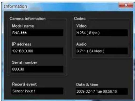
File dialog
Model name: Model name of the video network station with which the file was recorded. IP address: IP address of the video network station with which the file was recorded. Serial number: Serial number of the video network station with which the file was recorded. Date&time: Recording date and time Movie: Video Codec Audio: Audio Codec
Record event: Type of event used for the recording: Sensor input, Camera tampering detection, VMF, Motion detection, Audio detection, Network disconnection.
Playing a video/audio file
Click (start) to start playback from the beginning of the selected file.
To freeze the movie temporarily, click (pause).
Click again to resume playback from the freeze point.
To stop playback, click (stop).
To start playback from the beginning, click to start) again.
Playback stops when the file is played to the end.
Playing from a specified point
Move the slider bar below the image display, and playback will start from the position of the slider bar.
Adjusting the sound
Adjust the playing sound volume by moving the
slider bar. Move it to the left end for minimum volume, and to the right end for maximum volume.
Click (speaker) to enable/disable sound (muting).
When sound muting is on, no sound will be heard, even if you move the slider bar.
Saving an image
Click the 7 capture) icon during playback or pause and the captured image is displayed in a pop-up dialog. To save the image, click Save on the dialog. You can specify the destination to which the image is to be stored, and select the JPEG or Bitmap format.
How to change the image display size
Click × 1/4, × 1/2, × 1, × 2 or Full at the top of the image to display the image in the selected magnification.
If you select × 1, the image is displayed in the original image display size of the file.
The × 2 button is only available when image size is 640 × 480 (VGA) or smaller.
The selected image display size is highlighted.
Assigning the IP Address to the unit using ARP Commands
This section explains how to assign an IP address to the unit using ARP (Address Resolution Protocol) commands without using the supplied SNC toolbox.
Note
When you turn on the camera, execute the ARP and PING commands within 5 minutes. Also when you restart the camera, execute the operation within 5 minutes.
1 Open the command prompt on the computer. When using Windows Vista or Windows 7, right click Command prompt in Start-All Programs-Accessories, and select Run as administrator.
2 Enter the IP address and the MAC address of the video network station to assign a new IP address, using the following ARP commands.
arp -s
Example:
arp -s 192.168.0.100 08-00-46-21-00-00 ping -t 192.168.0.100
3 When the following line is displayed on the command prompt, hold down Ctrl and press C. Display stops.
Reply from 192.168.0.100:bytes=32 time...
You will normally receive a reply after about 5 repetitions of “Request time out.”
4 Wait until the execution of PING finishes, then input the following code.
arp -d 192.168.0.100
Note
If you do not receive a reply, check the following:
- Did you enter the ARP commands within 5 minutes after it was turned on?
If not, turn off the camera and restart the operation.
- Is the NETWORK indicator on the camera flashing? If the indicator goes off, the network connection has a problem. Connect the network correctly.
– Did you enter the IP address previously used for another device?
Assign a new IP address to the camera.
- Do the computer and the unit have the same network address?
If not, set the same network address on the computer and the camera.
Using the SNMP
This unit supports SNMP (Simple Network
Management Protocol). You can read MIB-2 objects using software such as SNMP manager software. This unit also supports the coldStart trap which occurs when the power is turned on or the unit restarts, and the Authentication failure trap, which informs of any illegal access using SNMP.
Using CGI commands, you can set the community name and access limitation, host to send traps, and some MIB-2 objects. To allow these settings, you need authentication by the administrator.
1. Inquiry Commands
You can check the SNMP Agent settings using the following CGI commands.
GET, POST
http://ip_adr/snmpdconf/inquiry.cgi?inqjs=snmp
(JavaScript parameter format)
http://ip_adr/snmpdconf/inquiry.cgi?inq=snmp
(standard format)
With the above inquiry, you can obtain the following setting information. The following explains the setting information using the inqjs=snmp (JavaScript parameter) format.
var sysDescr="SNT-EX101", "SNT-EX101E",
"SNT-EX104", "SNT-EP104", "SNT-EX154",
“SNT-EP154”, “SNT-RS1U”, “SNT-RS3U” ...①
var sysObjectID="1.3.6.1.4.1.122.8501" ...②
var sysLocation="...③
var sysContact="...④
var sysName="...⑤
var snmpEnableAuthenTraps="1" ...⑥
var community="public,0.0.0.0,read,1" ...⑦
var community="private,192.168.0.101,read,2" ...⑧
var trap="public,192.168.0.101.1" ...⑨
①describes the case of "mib-2.system.sysDescr.0". You cannot change this parameter.
②describes the case of "mib-2.system.sysObjectID.0". You cannot change this parameter.
③describes the case of "mib-2.system.sysLocation.0". This field is used to describe information on the location of this camera. Nothing is set at the factory.
④describes the case of "mib-2.system.sysContact.0". This field is used to describe information on the administrator of this camera. Nothing is set at the factory.
⑤describes the case of “mib-2.system.sysName.0”. This field is used to describe the administration node of this camera. Nothing is set at the factory.
⑥describes the case of “mib-2.snmpEnable AuthenTraps.0”. This example shows when “1” (enable) is set. In this setting, a trap occurs when there is an authentication failure. When “2” (disable) is set, no authentication failure trap occurs.
⑦describes the community attributes. This example shows the identification number “ID=1,” the community name “public,” and enables read from any IP address (0.0.0.0).
⑧ describes the community attributes, similar to ⑦. This example shows the identification number ID=2, the community name “private,” and enables reading by SNMP request packet from the host “192.168.0.101”.
⑨describes the attributes to send a trap. This example shows the identification number “ID=1,” the community name “public,” and enables sending of traps to the host having the IP address “192.168.0.101”.
2. Setting Commands
The unit supports the following SNMP setting commands.
First, perform the settings of the following parameters.
1) sysLocation=
2) sysContact=
3) sysName=
4) enaAuthTraps=
5) community=
6) trap=
7) delcommunity=
8) deltrap=
When you have finished changing the SNMP setting information using the above parameters 1) to 8), check the changed settings using an inquiry command. If the changed settings are OK, restart the SNMP using the following CGI command.
SNMP restart command
Glossary
ActiveX control
A component program object that can be used with web pages or other application programs. The technology for creating ActiveX control is part of software developed by Microsoft.
AES
Abbreviation for Advanced Encryption Standard. This is the next-generation standard of encryption, adopted by the U.S. government.
ARP commands
The commands for checking the entry of the IP address and MAC address in a host computer, or for updating them.
Bandwidth control
To limit the amount of transmitted data.
Bit rate
The rate at which data bits are transmitted.
CA (Certificate Authority)
A private authority that issues and controls digital certificates to be used for authentication regarding network access.
Capture
To display the audio and video digital data from video devices on a computer.
Codec
Software/hardware for coding/decoding video and audio data.
Common name
A URL to be typed in the browser when you access a website employing SSL (Secure Sockets Layer) protocol with the security function. Access is successful after the URL of the website is verified as matching the server's common name.
Contrast
The difference in tone between the lightest and darkest portions of the image.
Default gateway
Device that can be used to access another network.
DHCP server
Acronym for Dynamic Host Configuration Protocol server. The IP address of a terminal without an individual IP address can be automatically distributed by the Dynamic Host Configuration Protocol (DHCP). The DHCP server assigns the IP addresses to the terminals.
Digital certificate
An electronic certificate that a CA (Certificate Authority) attests that a public key to cancel a secret code is issued by an authentic publisher.
DNS server
Acronym for Domain Name System server. As an IP address required for connecting to the device on an IP network is numerical and difficult to remember, the Domain Name System was established. A domain name is alphabetic and is easier to remember. When a client computer uses a domain name to connect to another computer, it asks a DNS server to translate the name into the corresponding IP address. The client computer can then obtain the IP address of the computer to be connected.
EAP method
Acronym for Extensible Authentication Protocol. This is a protocol extended from PPP (Point-to-Point Protocol) and having an authentication function.
EAP-TLS authentication
TLS is an authentication protocol of the EAP methods using Transport Layer Security. By using digital certificates and other methods, EAP-TLS prevents data falsification, eavesdropping and spoofing.
Frame rate
The number of frames of a moving image that can be transmitted per a second.
FTP client
Software to be used for accessing the FTP server.
FTP server
A server to be used to transfer files via a network.
HTTP port
A port used to communicate between the web server and the web client, such as a web browser.
H.264
An image compression format. The standard written by the JVT (Joint Video Team) a joint organization for standardization (composed of ISO and ITU-T. H.264), is capable of transmitting video data at a higher compression rate than that of MPEG4.
IP address
Acronym for Internet Protocol Address. An individual IP address is basically assigned to each piece of equipment connected to the Internet.
JPEG
Acronym for Joint Photographic Expert Group. The still image compression technology or standards of ISO (International Organization for Standardization) and ITU-T. Popularly used as an image compression format on the Internet, etc.
MAC address
A network address that uniquely identifies each LAN card.
MPEG4
Acronym for Moving Picture Experts Group4. One of the MPEG standards for image compression format aiming to transmit images at a high compression rate with lower picture quality.
Multicast
The class D IP address assigned between 224.0.0.0 and 239.255.255.255. Using this IP address enables you to transmit the same data to multiple equipment.
Network address
The portion that identifies the local network (subnet) in an IP address.
Network bandwidth
Bit rate that can be used for networking.
NTP server
Network time server that transmits and receives time information over the networks.
Passive mode
The mode whereby a client FTP allows TCP connection for data transmission to the FTP server.
POP server
A server for storing incoming e-mail until you have read it.
Primary DNS server
One of the DNS servers that can first reply to a request by connected devices or other DNS servers.
Proxy server
A server or software that acts as an intermediary between a local network and the Internet so that it can connect to the Internet in place of a computer on a local network.
PSK
Abbreviation for Pre-Shared Key. This is a shared key to make an encryption key, used with TKIP in WPA encryption standard. PSK sometimes means an authentication system using a key previously shared.
QoS
Enter a value in the DSCP (Differential Service Code Point) field included in the IP header to control communication service quality.
RADIUS client
RADIUS (Remote Authentication Dial-in User Service) is an authentication and accounting protocol managing network access, and a RADIUS client is a party that accesses the network.
In Internet connecting service, a Network Access Server (NAS) such as that for dial-up and broadband access server is a RADIUS client. In a wireless LAN system, a wireless LAN access point is a RADIUS client.
Saturation
The degree to which a color is pure.
Secondary DNS Server
Subsidiary DNS server used when a primary DNS server cannot be used.
Shared secret
A character string to be used for mutual authentication between a RADIUS server and RADIUS client.
Sharpness
The degree to which the boundary of two portions is clearly distinguished.
SMTP server
A server for sending or relaying e-mail messages between servers.
SNMP
A protocol for monitoring and managing network devices.
SSL
Acronym for Secure Sockets Layer. This is a protocol developed by Netscape Communications Corporation to be used for communications of encrypted data on the Internet.
Subnet mask
32-bit stream used to distinguish the subnet address from an IP address.
TCP
Acronym for Transmission Control Protocol. A standard protocol used for Internet connection. Compared with the other protocol, UDP, TCP provides reliable communication but communication speed is slower.
TKIP
Acronym for Temporal Key Integrity Protocol. This is used in WPA encryption for a wireless LAN. TKIP provides high security since it changes encryption keys based on PSK during on-going communication.
UDP
Acronym for User Datagram Protocol. A standard protocol used for Internet connection. Compared with the other protocol, TCP, UDP can transmit data faster, but reliable communication is not guaranteed.
Unicast
Transmission of data to specified equipment on a network by specifying a single address.
WPA
Acronym for Wi-Fi Protected Access. This is an encryption standard for a wireless LAN. It provides higher security than the conventional WEP (Wired Equivalent Privacy) standard. In WPA, TKIP is used for the encryption method, and PSK and EAP are used for the authentication protocol.
WPA2
Abbreviation for Wi-Fi Protected Access 2. WPA2 is a standard with which AES (Advanced Encryption Standard) is added to WPA.
802.1X
A standard that performs user authentication and dynamic key generation and traffic on a LAN.
Index
Numerics
802.1X....42,94
A
Access log 28
Active Directory 45
ActiveX control....7
ActiveX Viewer 12, 13
Adaptive rate control 31
Adjust.... 25
Administrator.... 11,48
Administrator e-mail address ....36, 54, 62
Administrator menu 22
AES....92
Alarm 55, 58, 62, 69
Alarm buffer .....24, 59, 63, 73
Alarm buffer Menu 73
Alarm duration.... 68
Alarm output .....18, 23, 67, 71
Alarm output Menu.... 67
Alarm recording.... 62
Alarm sending.... 55, 58
ARP commands 89
Audio 29,48
Audio codec 29
audio output 69
Audio port number.... 32
Audio upload.... 29
Authentication....35, 54, 61
authentication server 43
authenticator.... 43
Automatically adjust clock for daylight saving time changes..... 25
B
Backup setting data.... 27
Bandwidth control.... 31
Bit rate.... 31
Brightness 29
C
CA (Certificate Authority)..... 43, 92
CA certificate.... 45, 46
CA certificate tab.... 39
Camera 23 28
Camera list 16 84
Camera Menu.... 28
camera position 51
Cancel button 22
Capacity warning 61
Capture.... 14
certificate request 44
CGI commands 90
Client certificate.... 44
Codec 73
Common....28, 53, 57, 61
Common name....92
Contrast....29
control authority.... 24
control panel.... 16
Current date & time 25
D
Date & time.... 25
date and time.... 25
Date and time format 25
daylight saving time.... 25
Default gateway 33
Default policy.... 49
delete 27
Delete custom homepage 27
Delete voice alert file 27
DHCP server 32
Digital certificate 92
DNS server.... 33
Domain suffix 33
downloading images 65
Dynamic IP address notification.... 35
E
EAP method 43,92
EAP-TLS authentication....92
Effective period .....53, 56, 59, 60, 63, 64, 68, 70
e-mail 35,53
e-Mail (SMTP)....23, 53, 70
e-Mail (SMTP) Menu 53
e-Mail (SMTP) notification ..... 35
e-mail address 36
End time 72
Exclusive control mode.... 24
extension 64
F
Factory default 27
factory settings 27
File 69,71
File attachment.... 55
file name..... 55, 56, 58, 59, 62, 63
focus 1416
Focus mode 28
folder structure ......64
format.... 27
format of date and time 25
Format USB memory.... 27
Frame rate 13,31
FTP 48
FTP client.... 23,71
FTP client function.... 57
FTP client Menu.... 57
FTP server.... 23,57
FTP server function.... 65
FTP server Menu.... 65
FTP server name 57
G
Glossary 92
Group preset positions 52
H
H.264....93
Home....13
Homepage 83
Host name 33
HTML output tab 86
HTTP method.... 36
HTTP notification 36
HTTP port number 33
HTTP request 36
HTTP server.... 36
|
image file.... 17
Image file name.....55, 58, 59, 62, 63
Image memory .....17, 23, 61, 71
Image memory Menu 60
Image quality.... 31
Image size 31
Initialize 27
Internet Authentication Service ..... 46
Internet Explorer 7
Interval 56,60,64

IP address 6,32
IP Setup Program ....87
IPv4 setting....32
IPv6 setting....33
J
JPEG....12
L
Layout 83
Logging in ....10
logging in ....12
M
MAC address....32
main viewer....13
Maximum wait number......25
memory 60 61, 65
Message.... 36,54
Method 36
Mic volume 29
Microphone 28
Mode 60 63, 67
monitor image 15
Motion detection 24,51,68
Motion detection Menu ....73
Multicast.... 18 93
Multicast address....32
Multicast streaming....32
N
Name 52
Network.... 23, 32
Network address/Subnet......49
network bandwidth....31
Network Menu 32
No....52
0
OK button....22
Operation time....24
Overwrite....61
P
pan/tilt 14, 16
Passive mode....58
Password ......36, 48, 54, 57, 62
PC clock 25
periodical e-mail sending ....56
Periodical recording ....63
Periodical sending ....56, 59
Picture....29
Play....69
playing audio....18
Plug-in free Viewer ....15
POP server.... 36,54,62
POP server name ...... 3654, 62
port number 36
Position....51
Position at alarm....51
Post-alarm period 73
Pre-alarm period....73
Preset 51
Preset call ....52
Preset position 15 17, 23
Preset position Menu....51
preset position name....52
Preset tour....52
Primary DNS server ....33
Privacy Masking tab....30
Private key password....44
Proxy port number......36
proxy server....36
Proxy server name....36
PSK....93
Q
QoS Tab....34
R
RADIUS client 93
Reboot 27
Recipient e-mail address .....36, 54
Recording capacity....73
recording capacity of the alarm buffer....73
recording images ....17, 60
Recording time 73
Remote path....58, 59
Repeat....69
Restore setting 27
Resume time on inactivity......52
Re-type password ....48, 58
S
Saturation 29
saves the setting data....27
Schedule 24,72
Schedule Menu....72
Secondary DNS server ....33
Security......23,49
Security function ....49
Security Menu 49
Security Warning....75
Selected root directory......61, 65
sending images ....17
Sensor input 1....51,68
Sensor input 2....51,68
Sequence....53
Sequence number clear.....55, 56, 58, 60, 62, 63
Serial number 24
Set....52
Setting....13
Setting Tab 49
Shared secret....93
Sharpness....29
Simple motion detection function 81
SMTP server.... 35, 53, 61
SMTP server name ...... 35 53, 61
SNC audio upload tool 87
SNC Desktop viewer....20
SNC toolbox....87
SNC video player 88
SNC Viewer 19
SNMP 90
Software version....24
special tags 37
SSL Menu....37
SSL 94
Start time 72
Stay time....53
Streaming....31
Subject 36,54
Subnet mask 33
Suffix....55, 56, 58, 60, 62, 63
Superimpose 26
supplicant....43
System 23, 24
System log 28
System Menu....24
System Utility....19
T
TCP 18
Test....69
Text 84
time difference 25
Time zone 25
Timer....71
title bar 24
Title bar name 24
TKIP 94
Toggle 71
tour 52
Transmission Mode.... 18
transmission port number...... 31
Trigger 23
Trigger Menu 70
U
UDP 31
Unicast 18,94
Unicast streaming 31
URL 36
USB memory 27,61,65
Use the same time schedule every day 72
User....11,23,46,48
User Menu.... 48
User name ...... 36 48, 54, 57, 62
Utility 13
V
Video codec 31,73
Video port number 31, 32
View size.... 13
Viewer authentication 49
Viewer mode.... 11,49
Viewer Setting 83
Voice alert....23, 69, 71
Voice alert Menu 69
volume 14
W
warning mail 61
welcome page 7
WPA....94
WPA2....94
Z
zoom.... 14, 16

Others
http://www.sony.net/
Sony Corporation
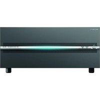


- Video Network Station
- Table of Contents
- Overview
- Preparation
- Operating the unit
- Administrating the unit
- Sending an Image via E-mail — e-Mail (SMTP)
- Sending Images to FTP Server — FTP client
- Recording Images in Memory — Image memory
- Downloading Images from the system
- Setting the Alarm Output
- Outputting Audio Linked to Alarm Detection
- Setting the Operations from the Viewer — Trigger
- Setting the Schedule
- Setting the Alarm Buffer — Alarm buffer
- Setting the Sensor input/Camera tampering detection/Motion detection/Audio detection
- Transmitting with External Equipment
- Configuring the Viewer — Viewer Menu .....83
- Others
- Using the SNC audio upload tool — Transmitting
- Using the SNC video player — Playing a Video/
- Assigning the IP Address to the unit using ARP
- Using the SNMP 90
- Glossary 92
- Features
- NOTICE TO USERS
- How to Use This User's Guide
- Jumping to a related page
- Software display examples
- Printing the User's Guide
- Installation Manual (printed matter)
- System Requirements
- CPU
- Memory
- os
- Web Browser
- Display
- Assigning the IP Address to the Camera
- Assigning an IP address using SNC toolbox
- Tips
- Accessing the System Using the Web Browser
- Note
- Using the SSL function
- When Internet Explorer is used
- When "Allow HTTP connection for some clients" (page 37) is checked
- For HTTP connection
- For SSL connection
- When the viewer of the unit is displayed for the first time
- Notes
- Tip
- To display the viewer correctly
- When using antivirus software, etc., on the computer
- Basic Configuration by the Administrator
- Precautions for Preventing Access to the Camera by an Unintended Third Party
- How to set up
- Administrator and User
- Logging in to System
- Logging in as a user
- About Viewers
- ActiveX Viewer
- When you display the main viewer of the unit for the first time
- Plug-in free Viewer
- Configuration of Main Viewer
- Main menu
- ActiveX
- Plug-in free
- Tool
- Set up
- Language
- Control panel section
- Information panel
- Screen Mode
- View size
- Image Codec
- Frame rate
- (Capture)
- (Run)/ (Stop Save Video)
- Volume
- Camera control panel
- Pan/Tilt control
- Zoom control
- Focus control
- (Exclusive control)
- Trigger panel
- Preset position panel
- Others panel
- Monitor image
- Main viewer using Plug-in free Viewer
- Monitor screen
- Control bar
- Setting
- Streaming start button
- Streaming stop button
- Trigger run button
- P Preset
- Save still image button
- Audio output volume slider
- ■ Control waiting time and control time for exclusive control
- Exclusive control button
- Camera list
- Operating the Camera
- Controlling via the control panel
- Moving the camera to a preset position
- Using the Trigger Button
- Sending a monitor image via e-mail
- Sending a monitor image to an FTP server
- Recording a camera image as a still image
- Controlling alarm output
- Playing an audio file stored in the system
- Switching Transmission Mode
- Using the System Utility
- SNC Viewer
- Installing the SNC viewer
- Using the SNC viewer
- JPEG framerate
- Image action
- Audio tab
- Mic
- Save tab
- Joystick tab
- SNC Desktop viewer
- Installing the SNC desktop viewer
- Using the SNC desktop viewer
- Camera address
- Image size
- How to control PTZ
- Note on the display of menu options
- Basic Operations of the Administrator Menu
- How to set up the Administrator menu
- Buttons common to every menu
- General notes on menus
- Configuration of the Administrator menu
- System
- Camera
- Network
- SSL
- 802.1X
- User
- Security
- Preset position
- e-Mail (SMTP)
- FTP client
- Image memory
- FTP server
- Edge Storage
- Alarm output
- Voice alert
- Trigger
- Schedule
- Alarm buffer
- Event Detection
- PTZ control I/F
- Viewer
- Configuring the System — System Menu
- System Tab
- Title bar name
- Serial number
- Software version
- Exclusive control mode
- Operation time
- Maximum wait number
- OK/Cancel
- Current date & time
- PC clock
- Date & time format
- Adjust
- Time zone
- Automatically adjust the clock for daylight saving time changes
- Superimpose Tab
- Superimpose
- On/Off
- Font size
- Style
- Superimpose format
- Camera Direction
- Initialize Tab
- Reboot
- Factory default
- Retain current network settings
- Backup setting data
- Restore setting
- Restore preset position and privacy masking settings
- Format USB memory
- Delete custom homepage
- Delete voice alert file
- Delete thumbnails
- Delete header logo
- Delete superimpose logo
- System log Tab
- Access log Tab
- Setting the Camera Image and Audio
- — Camera Menu
- Common Tab
- Focus mode
- Audio codec
- Audio
- Mic volume
- Codec
- Echo canceler
- Audio noise reduction
- Dynamic range compressor
- Audio upload
- Picture Tab
- Visibility Enhancer
- XDNR
- Brightness
- Saturation
- Sharpness
- Contrast
- Privacy Masking tab
- Preview screen
- Control buttons
- Pan/Tilt operation
- Zoom operation
- Position
- Color
- Setting a privacy mask
- Click OK.
- Video codec Tab
- Image 1 and Image 2
- Bit rate
- I-Picture Interval
- Adaptive rate control
- Image quality
- Bandwidth control
- Streaming Tab
- Unicast streaming
- Video port number
- Audio port number
- Multicast streaming
- Multicast address
- Configuring the Network — Network Menu
- Network Tab
- MAC address
- Ethernet status
- IPv4 setting
- IP address
- Subnet mask
- Default gateway
- DNS server
- Primary DNS server
- Secondary DNS server
- MTU
- Host name
- Domain suffix
- HTTP port number
- IPv6 setting
- Prefix
- IPv6 MTU
- QoS Tab
- IPv4 QoS setting
- Rule
- No.
- Network address
- Subnet
- Port
- Protocol
- DSCP
- Set
- Delete
- Up
- Down
- QoS table
- IPv6 QoS
- Dynamic IP address notification Tab — Notifying the IP Address
- e-Mail (SMTP) notification
- SMTP server name
- SMTP port number
- Use TLS
- STARTTLS
- Authentication
- POP mode
- Waiting time after POP
- POP server name
- POP port number
- Authentication mode
- User name, Password
- Recipient e-mail address
- Administrator e-mail address
- Subject
- Message
- HTTP notification
- URL
- Proxy server name
- Proxy port number
- Method
- About the special tags
- Setting the SSL function — SSL Menu
- SSL function
- Certificate options
- Certificates
- To import the certificate
- Generating a self-signed certificate
- To display certificate information
- Status
- To delete the imported certificate or self-signed certificate
- Private key password
- Reset
- CA certificate tab — Adding the CA certificate for client authentication
- SSL client certificate
- Trusted CA certificate 1 to 4
- To import the CA certificate
- To display the information of the CA certificate
- To delete the CA certificate
- How to install the CA certificate
- Click Next.
- Select Automatically selects the certificate store based on the type of certificate and click Next. Completing the Certificate Import Wizard appears.
- Check the contents, then click Finish. The CA certificate will be installed.
- To remove an installed CA certificate
- In Internet Explorer, click in the order Tools, Internet options, Content tab and Certificates. The Certificates dialog appears.
- Select the certificate you want to remove. The CA certificate is usually stored in Trusted Root Certification Authorities.
- Click Remove. Do you want to delete the certificate appears to confirm.
- Click Yes The certificate will be removed. There may be a case that a certificate cannot be removed by the steps above due to the type of certificate. Check the installation condition and remove it following the steps below.
- Using the 802.1X Authentication Function — 802.1X Menu
- System configuration of 802.1X network
- Supplicant
- Authenticator
- Authentication server
- CA (Certificate Authority)
- Common Tab – Basic setting of 802.1X authentication function
- 802.1X authentication function
- Wired interface
- Wired interface status
- EAP identity
- EAP password
- EAP method
- Client certificate Tab
- Client certificate request
- To import the client certificate
- To display the information of the client certificate
- To delete the client certificate
- CA certificate Tab
- Setting the 802.1X authentication function – Example of Windows Server 2003
- Before setting
- Active Directory (domain controller)
- Windows IAS configuration
- CA configuration
- Creating a security group for Active Directory
- Configuring the Internet Authentication Service
- Adding a user
- Issuing the CA certificate
- Downloading the client certificate
- When "Use a key pair from a CA" is selected
- Setting the User — User Menu
- Administrator
- User 1 to 9
- User name
- Password
- Re-type password
- FTP
- Viewer mode
- Viewer authentication
- Setting the Security — Security Menu
- Setting Tab
- Security function
- Default policy
- Network address/Subnet 1 to Network address/Subnet 10
- Referer check tab
- Referer check
- Exception list
- Port No.
- Saving the Camera Position and Action — Preset position Menu
- Position Tab — Saving pan/tilt/zoom position
- Position at alarm
- Sensor input 1 (S1)
- Sensor input 2 (S2)
- Sensor input 3 (S3)
- Sensor input 4 (S4)
- Camera tampering detection (TP)
- VMF (VM)
- Motion Detection (MD)
- Audio detection (AD)
- Preset
- Name
- Call
- Clear Thumbnail
- Thumbnail
- Group preset positions
- New Group
- Rename
- Clear
- Position Tour Tab — Setting a position tour
- Tour
- Resume time on inactivity
- Tour A to Tour E
- Sequence
- Stay time
- Effective period
- Sending an Image via E-mail — e-Mail (SMTP) Menu
- Common Tab — Setting the e-Mail (SMTP) Function
- Waiting time after POP authentication
- Alarm sending Tab — Setting the e-mail sending mode when detecting the alarm
- Alarm sending
- File attachment
- Image file name
- Suffix
- Sequence number clear
- Alarm
- Periodical sending Tab — Setting the periodical e-mail sending mode
- Periodical sending
- Interval
- Abnormal sending tab — Setting the abnormal e-mail sending mode
- Abnormal sending
- Resume sending
- Sending Images to FTP Server
- — FTP client Menu
- Common Tab — Setting the FTP client function
- FTP client function
- FTP server name
- Passive mode
- Alarm sending Tab — Setting the FTP client action when detecting the alarm
- e-Mail (SMTP) menu
- FTP client menu
- Trigger menu
- Remote path
- Periodical sending Tab — Setting the periodical FTP client activity
- Mode
- Recording Images in Memory — Image memory Menu
- Common Tab — Setting the image memory function
- Selected root directory
- Overwrite
- Capacity warning
- Alarm recording Tab — Setting the Image memory function when detecting the alarm
- Alarm recording
- Periodical recording Tab — Setting the periodical recording mode
- Periodical recording
- Folder structure of image memory
- About the extension of a file
- Downloading Images from the system — FTP server Menu
- FTP server function
- USB memory
- Recording status
- Video recording
- Audio recording
- Recording capacity
- Recording time
- Pre-alarm duration
- Post-alarm duration
- Recording mode
- IP address monitoring
- Folder structure of Edge Storage
- Setting the Alarm Output — Alarm output Menu
- Alarm output Tab
- Sensor input 1
- Sensor input 2
- Sensor input 3
- Sensor input 4
- Camera tampering detect
- VMF
- Motion detection
- Audio detection
- Alarm duration
- — Voice alert Menu
- Voice alert 1, 2, 3 Tab
- File
- Test
- Repeat
- Setting the Operations from the Viewer — Trigger Menu
- Duration
- Voice alert 1, 2, 3
- Audio file
- Setting the Schedule — Schedule Menu
- Use the same time schedule every day
- Mon (Monday) to Sun (Sunday)
- Start time, End time
- Setting the Alarm Buffer — Alarm buffer Menu
- Setting the Sensor input/ Camera tampering detection/Motion detection/Audio detection
- — Event detection menu
- Sensor input tab — Set the sensor input
- Sensor input mode
- Camera tampering detection tab — Set the camera tampering detection
- Camera tampering detection
- Motion detection tab — Set the motion/VMF detection
- What are VMF functions-Video Motion Filter
- Passing
- Existing
- Appearance
- Disappearance
- Capacity
- When the Motion detection menu is displayed for the first time
- Setting items for motion detection
- Regular positions
- Target of setting
- Detection settings
- Detection area
- Configuring the detection area
- Adding an active area
- Adding an inactive area
- Deleting a region
- Adding a vertex
- Deleting a vertex
- Detection sensitivity
- Detection response
- Detection size
- Moving shadow exemption
- VMF setting items
- Number of filters
- Filter type
- Enable/Disable checkbox for filter
- Filter order switching button
- Specifying the time for "When all occurs in order"
- VMF status indicator
- Filter settings
- VMF status indicator of each filter
- Passing object trigger line
- Trigger direction setting
- Passing object trigger position
- Trigger size
- Trigger speed
- Full-screen display button
- Stretch bar
- Simple motion detection function
- Detection level
- Motion level
- Audio detection tab — Set the audio detection
- Sensitivity
- Manual sensitivity
- — PTZ control I/F Menu
- Interface
- Serial setting
- Standard
- Camera ID
- Camera Operation Protocol
- Speed
- Pan
- Tilt
- Zoom
- Focus
- TCP port number
- Baud rate
- Parity bit
- Character length
- Stop bits
- Configuring the Viewer — Viewer Menu
- Homepage
- Header
- Button style
- Logo
- Text color, Background color 1, and Background color 2
- Background color
- Registering in Cameras
- Text
- Text1 text, Text2 text and Text3 text
- Text1 link, Text2 link and Text3 link
- Display comment when camera is selected
- Monitor
- Initial streaming
- Initial image size
- Initial image codec
- Initial PTZ
- Initial frame rate
- Initial image
- Initial Sound
- Show menu
- HTML output tab
- Embedded script
- HTML sample
- Using the SNC toolbox
- Using the SNC audio upload tool — Transmitting Audio to Camera
- Using the SNC video player — Playing a Video/Audio File Recorded with the unit
- Installing the SNC video player
- Using the SNC video player
- File dialog
- Playing a video/audio file
- Playing from a specified point
- Adjusting the sound
- Saving an image
- How to change the image display size
- Assigning the IP Address to the unit using ARP Commands
- Using the SNMP
- Inquiry Commands
- Setting Commands
- SNMP restart command
- Glossary
- ActiveX control
- AES
- ARP commands
- Capture
- Common name
- DHCP server
- Digital certificate
- EAP-TLS authentication
- HTTP port
- H.264
- JPEG
- MPEG4
- Multicast
- Network bandwidth
- NTP server
- POP server
- Proxy server
- PSK
- QoS
- RADIUS client
- Shared secret
- SMTP server
- SNMP
- TCP
- TKIP
- UDP
- Unicast
- WPA
- WPA2
- Index
- Numerics
- A
- B
- C
- D
- E
- F
- G
- H
- |
- J
- L
- M
- N
- 0
- P
- Q
- R
- S
- T
- U
- V
- W
- Z
Brand : SONY
Model : SNTEP154
Category : Server