
AWS-G500HD - Server SONY - Free user manual and instructions
Find the device manual for free AWS-G500HD SONY in PDF.


| Product Type | Professional Video Server |
| Brand | Sony |
| Model | AWS-G500HD |
| Dimensions (W x D x H) | 19" rackmount, 2U height, approx. 430 x 500 x 88 mm |
| Weight | Approximately 15-20 kg |
| Power Supply | AC 100-240 V, 50/60 Hz, dual redundant optional |
| Power Consumption | Approximately 300-400 W typical |
| Operating Temperature | 5°C to 40°C (41°F to 104°F) |
| Storage Temperature | -20°C to 60°C (-4°F to 140°F) |
| Humidity | 10% to 90% non-condensing |
| Video Formats Supported | HD-SDI, 3G-SDI, HDMI (depending on options) |
| Audio Formats Supported | Embedded audio, AES/EBU |
| Network Interface | Gigabit Ethernet (10/100/1000BASE-T) |
| Storage | Internal SSD/HDD bays, expandable |
| Cooling | Internal fans with airflow management |
| Mounting | 19-inch rack mounting kit included |
| Cleaning Instructions | Use dry air or soft brush for vents; avoid liquids |
| Safety Precautions | Ensure proper grounding, avoid overloading circuits |
| Spare Parts Availability | Contact Sony service for replacement parts |
| User Manual | Available for free download in PDF |
Frequently Asked Questions - AWS-G500HD SONY
User questions about AWS-G500HD SONY
0 question about this device. Answer the ones you know or ask your own.
Ask a new question about this device
Download the instructions for your Server in PDF format for free! Find your manual AWS-G500HD - SONY and take your electronic device back in hand. On this page are published all the documents necessary for the use of your device. AWS-G500HD by SONY.
USER MANUAL AWS-G500HD SONY
Live Content Producer
Operating Instructions
Software Version 2.25 and Later
Read this manual together with the Operating Instructions for the AWS-G500E.
ANYCAST STATION

MEMORY STICK™

AWS-G500HD
Owner's Record
The model and serial numbers are located at the bottom.
Record these numbers in the spaces provided below. Refer to them whenever you call upon your Sony dealer regarding this product.
Model No. ____ Serial No. ____
WARNING
To reduce the risk of fire or electric shock, do not expose the unit to rain or moisture.
To avoid electrical shock, do not open the cabinet. Refer servicing to qualified personnel only.
THIS APPARATUS MUST BE EARTHED.
WARNUNG
When installing the unit, incorporate a readily accessible disconnect device in the fixed wiring, or connect the power plug to an easily accessible socket-outlet near the unit. If a fault should occur during operation of the unit, operate the disconnect device to switch the power supply off, or disconnect the power plug.
WARNUNG
WARNING: THIS WARNING IS APPLICABLE FOR USA ONLY.
If used in USA, use the UL LISTED power cord specified below.
DO NOT USE ANY OTHER POWER CORD.
Plug Cap Parallel blade with ground pin (NEMA 5-15P Configuration)
Cord Type SJT, three 16 or 18 AWG wires
Length Minimum 1.5 m, Less than 2.5 m (8 ft 3 in)
Rating Minimum 10 A, 125 V
Using this unit at a voltage other than 120 V may require the use of a different line cord or attachment plug, or both. To reduce the risk of fire or electric shock, refer servicing to qualified service personnel.
WARNING: THIS WARNING IS APPLICABLE FOR OTHER COUNTRIES.
- Use the approved Power Cord (3-core mains lead) / Appliance Connector / Plug with earthing-contacts that conforms to the safety regulations of each country if applicable.
- Use the Power Cord (3-core mains lead) / Appliance Connector / Plug conforming to the proper ratings (Voltage, Ampere).
If you have questions on the use of the above Power Cord / Appliance Connector / Plug, please consult a qualified service personnel.
WARNUNG
For the customers in the USA
This equipment has been tested and found to comply with the limits for a Class A digital device, pursuant to Part 15 of the FCC Rules. These limits are designed to provide reasonable protection against harmful interference when the equipment is operated in a commercial environment. This equipment generates, uses, and can radiate radio frequency energy and, if not installed and used in accordance with the instruction manual, may cause harmful interference to radio communications. Operation of this equipment in a residential area is likely to cause harmful interference in which case the user will be required to correct the interference at his own expense.
You are cautioned that any changes or modifications not expressly approved in this manual could void your authority to operate this equipment.
All interface cables used to connect peripherals must be shielded in order to comply with the limits for a digital device pursuant to Subpart B of Part 15 of FCC Rules.
This device complies with Part 15 of the FCC Rules. Operation is subject to the following two conditions: (1) this device may not cause harmful interference, and (2) this device must accept any interference received, including interference that may cause undesired operation.
For the customers in Canada
This Class A digital apparatus complies with Canadian ICES-003.
The nameplate is located on the bottom.
IMPORTANT
Danger of explosion if battery is incorrectly replaced.
Replace only with the same or equivalent type recommended by the manufacturer.
When you dispose of the battery, you must obey the law in the relative area or country.
ATTENTION
For the customers in Europe, Australia and New Zealand
WARNING
This is a Class A product. In a domestic environment, this product may cause radio interference in which case the user may be required to take adequate measures.
For the customers in Europe
The manufacturer of this product is Sony Corporation, 1-7-1 Konan, Minato-ku, Tokyo, Japan.
The Authorized Representative for EMC and product safety is Sony Deutschland GmbH, Hedelfinger Strasse 61, 70327 Stuttgart, Germany. For any service or guarantee matters please refer to the addresses given in separate service or guarantee documents.
This apparatus shall not be used in the residential area.
For the customers in the USA
Lamp in this product contains mercury. Disposal of these materials may be regulated due to environmental considerations. For disposal or recycling information, please contact your local authorities or the Electronic Industries Alliance (www.eiae.org).
For the State of California, USA only
Perchlorate Material - special handling may apply, See
www.dtsc.ca.gov/hazardouswaste/perchlorate Perchlorate Material : Lithium battery contains perchlorate.
For the customers in Taiwan only

廢電池請回收
Table of Contents
Introduction ......6
About This Unit ....6
Using This Manual....6
About the Standard Configuration Modules ....6
Names and Functions of Parts ....7
Rear Panel 7
Connections 7
Limitations When Using the Standard Configuration Modules....9
Notes on Menu Settings 9
Specifications....10
Introduction
About This Unit
The AWS-G500HD Anycast Station Live Content Producer is an audiovisual production system equipped with video switching, camera control, and live Internet distribution systems. The basic functions of the AWS-G500HD unit are the same as those of the AWS-G500E, but the AWS-G500HD allows switching between HD analog and HD SDI input images with the standard configuration modules. In addition, the AWS-G500 unit's ability to handle SD signals can be achieved on the AWS-G500HD by installing an optional interface module.
Using This Manual
This manual contains only the minimum of information regarding the AWS-G500HD unit. When using the AWS-G500HD, read this manual together with the Operating Instructions for the AWS-G500E.
Caution
The menu screens that appear when HD signals are input to this unit are different from those described in the AWS-G500E Operating Instructions, which appear when SD signals are input.
About the Standard Configuration Modules
The AWS-G500HD is equipped with the following standard interface modules:
• HD video interface module
• HD serial digital interface module
This manual refers to these interface modules as the “standard configuration modules.”
Names and Functions of Parts
The rear panel of the AWS-G500HD is the only part that differs from the AWS-G500E. For details on the other parts, refer to the AWS-G500E Operating Instructions.
Rear Panel

For details on the function of each part on the rear panel, refer to the AWS-G500E Operating Instructions.
Caution
- To maintain proper heat ventilation from the unit, be sure to keep empty slots covered with blank panels.
- If the HD SDI IN connectors of the HD serial digital interface module are open, a malfunction may occur in the HD SDI circuit due to noise from the nearby equipments. When using this module, be sure to attach 75 terminators to the HD SDI IN connectors so as not to be open.
Connections
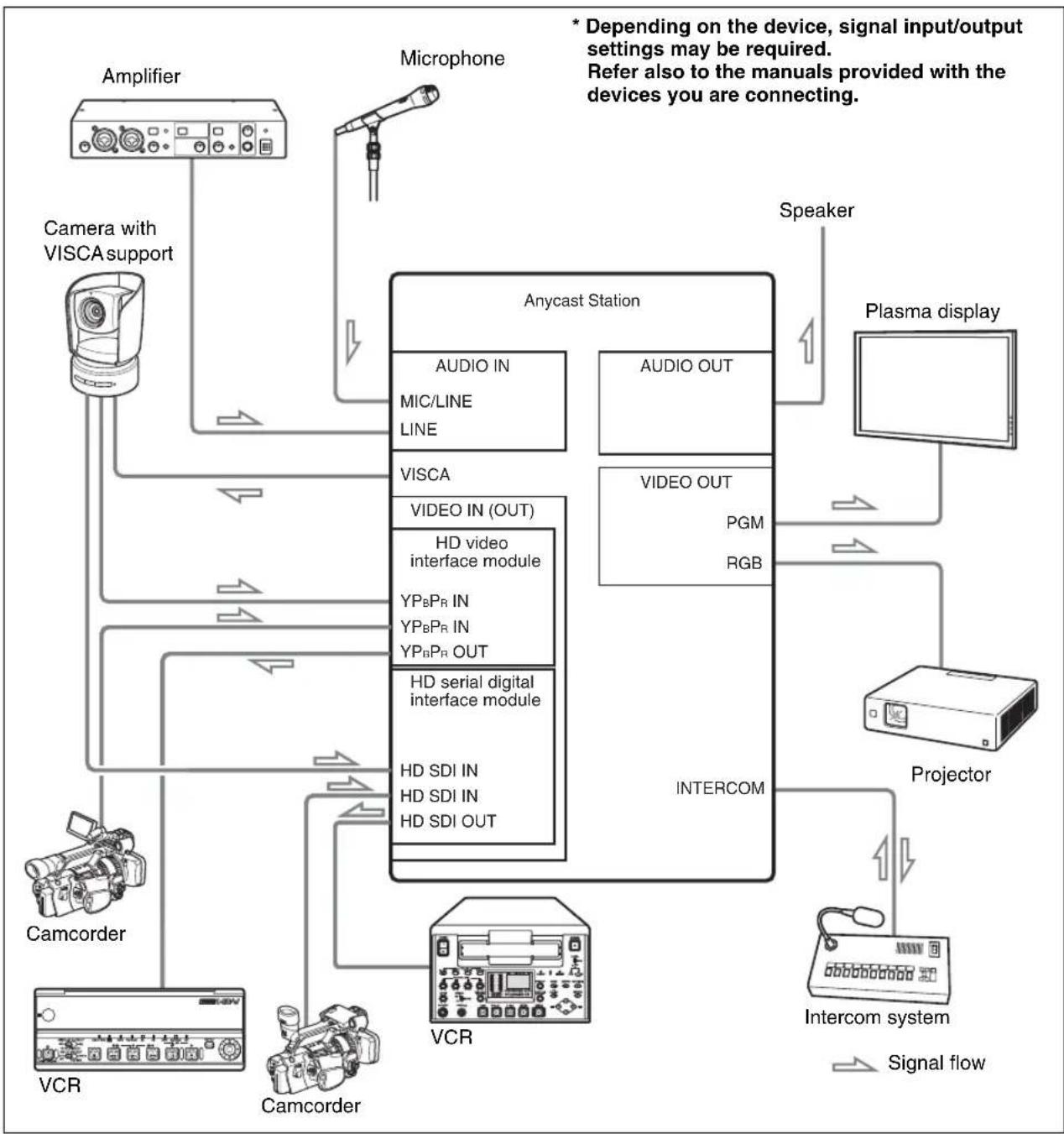
The following figure shows a sample system configuration and signal flow. For details on how to make the connections, refer to the AWS-G500E Operating Instructions.
After connecting each device, you must configure settings on the unit for each input and output signal.
For details on settings for each input and output signal, refer to the AWS-G500E Operating Instructions.
System configuration example when using the standard configuration modules
flowchart
graph TD
    A["Amplifier"] --> B["Camera with VISCA support"]
    B --> C["Microphone"]
    C --> D["Anycast Station"]
    D --> E["Speaker"]
    D --> F["Plasma display"]
    D --> G["Projector"]
    G --> H["Intercom system"]
    H --> I["Signal flow"]
    D --> J["Microcorder"]
    J --> K["VCR"]
    J --> L["Camcorder"]
    D --> M["Video IN (OUT)"]
    M --> N["HD video interface module"]
    M --> O["HD serial digital interface module"]
    M --> P["HD SDI IN HD SDI OUT"]
    D --> Q["Audio IN MIC/LINE LINE"]
    D --> R["AUDIO OUT"]
    D --> S["VIDEO OUT PGM RGB"]
    D --> T["VDIGO OUT"]
    D --> U["VDIGO OUT"]
    D --> V["VDIGO OUT"]
    D --> W["VDIGO OUT"]
    D --> X["VDIGO OUT"]
    D --> Y["VDIGO OUT"]
    D --> Z["VDIGO OUT"]
    style A fill:#f9f,stroke:#333
    style J fill:#ccf,stroke:#333
    style K fill:#cfc,stroke:#333
    style L fill:#cfc,stroke:#333
    style M fill:#fcc,stroke:#333
    style N fill:#cff,stroke:#333
    style O fill:#cff,stroke:#333
    style P fill:#cff,stroke:#333
    style Q fill:#ffc,stroke:#333
    style R fill:#ffc,stroke:#333
    style S fill:#ffc,stroke:#333
    style T fill:#ffc,stroke:#333
    style U fill:#ffc,stroke:#333
    style V fill:#ffc,stroke:#333
    style W fill:#ffc,stroke:#333
    style X fill:#ffc,stroke:#333
    style Y fill:#ffc,stroke:#333
    style Z fill:#ffc,stroke:#333
Caution
- Use the shortest possible cable type (especially with unregulated RGB). Shorter cables are recommended because, in general, using long cables to connect devices increases the risk of signal noise. Even when connecting this unit to another, it is best to use the shortest cables possible.
- Be careful with the connector portions of the interface modules, which may become hot depending on the conditions of operation.
Limitations When Using the Standard Configuration Modules
- You cannot record to an external hard disk.
- You cannot perform recording and playback operations for VCRs from the unit.
For details on changing the setting, refer to "Setting the PGM Output Aspect Ratio" in the AWS-G500E Operating Instructions.
Notes on Menu Settings
When the factory default settings are used, or when [Load] under [Job] in the top menu is set to [Default], the unit starts with the AWS-G500E default settings (for the SD signals). After that, when handling the HD signals by the unit with the standard configuration modules, carry out the following menu settings:
- In the top menu, [S3-1 RGB] and [S3-2 RGB] appear as the [Input] settings for [5] and [6] respectively of the [Video Input Assign] settings.
Depending on your intended use, select [No Assign] for the [Input] setting or select [SLOT1] or [SLOT2] input.
For details on how to change the settings, refer to “Assigning video input signals to the selection buttons” of the AWS-G500E Operating Instructions.
Required settings
- [PGM OUT Aspect] under [Video Output] in the top menu is set to [4:3]. Based on this setting, the PGM and PVW viewers on the operation screen display in 4:3 aspect ratio, and signal output is disabled from the output connectors of the standard configuration modules. Change the setting to [16:9 HD]. The PGM and PVW viewers display in 16:9 aspect ratio, and the HD lamps beside the output connectors of the standard configuration modules light, indicating that signal output is enabled.
Specifications
General
Power Requirements
AC 100 V to 240 V, 50/60 Hz
Power Consumption
1.6 A-0.8 A
Operating Temperature
5^ to 40^ (41°F to 104°F)
Dimensions (w × h × d)
424 × 114 × 339 ~mm
(16^3/4× 4^1/2× 13^3/_8 inches)
Mass Approximately 8.0 kg
(17 lb 10 oz)
Video Signals
VIDEO INPUTS (standard configuration)
YPBPR IN
D-Sub Shrink 15-pin Type × 2
(Female)
720/59.94p, 720/50p,
1080/59.94i, 1080/50i
Y: 1.0 Vp-p, 75 Ω, with Sync
P_B : 0.7 Vp-p (75 Ω)
Pr: 0.7 Vp-p (75 Ω)
HD SDI IN BNC × 2
720/59.94p, 720/50p,
1080/59.94i, 1080/50i
800 mVp-p (75 Ω)
SMPTE292M compliant
HD input signals
| Video format | fH (kHz) | fV (Hz) | Sync |
| 1080/60i | 33.750 | 59.94 | S on Y |
| 1080/50i | 28.130 | 50.000 | S on Y |
| 720/60p | 45.000 | 59.94 | S on Y |
| 720/50p | 37.500 | 50.000 | S on Y |
Pin assignment

| Pin | Signal | Pin | Signal | Pin | Signal |
| 1 | Pr (X) | 6 | Pr (GND) | 11 | NC |
| 2 | Y (X) | 7 | Y (GND) | 12 | NC |
| 3 | Pb (X) | 8 | Pb (GND) | 13 | Reserved |
| 4 | NC | 9 | NC | 14 | Reserved |
| 5 | GND | 10 | GND | 15 | NC |
VIDEO OUTPUTS
Composite BNC Type × 1
Video: 1.0 Vp-p, 75 Ω,
Sync negative
S-video DIN Type × 1
Y: 1.0 Vp-p, 75 Ω,
Sync negative
C: 0.286 Vp-p at burst, 75 Ω, (NTSC)
C: 0.3 Vp-p at burst, 75 Ω, (PAL)
YP_BPR OUT D-Sub Shrink 15-pin Type × 1 (Female)
720/59.94p, 720/50p,
1080/59.94i, 1080/50i
Y: 1.0 Vp-p, 75 Ω, with Sync
P_B : 0.7 Vp-p (75 Ω)
Pr: 0.7 Vp-p (75 Ω)
HD SDI OUT BNC × 1
720/59.94p, 720/50p,
1080/59.94i, 1080/50i
800 mVp-p (75 Ω)
SMPTE292M compliant
RGB (VIDEO OUT)
15k RGB (50 Hz/59.94 Hz)
R: 0.7 Vp-p (75 Ω)
G: 0.7 Vp-p (75 Ω)
B: 0.7 Vp-p (75 Ω)
SYNC: Composite sync TTL output - audio output
RGB D-Sub Shrink 15-pin Type ×2 (Female)
XGA (1,024 × 768 60 Hz,
75 Hz)
SXGA (1,280 × 1,024 60 Hz)
WXGA (1,280 × 768 60 Hz, 75 Hz)
| Menu setting | Signal format | FH (kHz) | FV (Hz) | Sync | |
| RGB OUT* | PGM OUT** | ||||
| XGA 60 Hz | - | XGA VESA (DMT) 60 Hz | 48.363 | 60.004 | H-negative V-negative |
| XGA 75 Hz | - | XGA VESA (DMT) 75 Hz | 60.023 | 75.029 | H-positive V-positive |
| SXGA 60 Hz | - | SXGA VESA (DMT) 60 Hz | 67.500 | 75.000 | H-positive V-positive |
| Vidco RGB | NTSC | 15k RGB 60 Hz | 15.734 | 59.940 | Composite sync |
| PAL | 15k RGB 50 Hz | 15.625 | 50.000 | Composite sync | |
| RGB OUT | - | WXGA 60 Hz | 47.693 | 59.992 | II-negative V-positive |
| WXGA 75 Hz | 60.091 | 74.926 | II-negative V-positive | ||
* For details of RGB OUT settings, refer to "Setting the RGB Output Signal Format" in the AWS-G500E Operating Instructions.
** For details of PGM OUT settings, refer to "Selecting the Video Output Signal Format" in the AWS-G500E Operating Instructions.
REF OUT BNC Type × 2
Sync: 0.286 Vp-p, 75 Ω, (NTSC)
Sync: 0.3 Vp-p, 75 Ω, (PAL)
C: 0.286 Vp-p at burst, 75 Ω, (NTSC)
C: 0.3 Vp-p at burst, 75 Ω, (PAL)
Audio Signals
AUDIO INPUTS
Analog Inputs 1-2
XLR/TRS Combo Type × 2
Ref. Level:
TRS Type × 4 / Ref. Level:
Pin × 2 / Ref. Level: -10 dBu
HD SDI IN BNC × 2
720/59.94p, 720/50p,
1080/59.94i, 1080/50i
Audio sampling rate:
20 bit 48 kHz 2 channels
(channels 1 and 2 or 3 and 4)
SMPTE299M compliant
AUDIO OUTPUTS
PGM OUT TRS Type × 2 / Ref.: +4 dBu /
Impedance: 150 Ω
MIX OUT Pin Type × 2 / Ref.: -10 dBu /
Impedance: 470 Ω
AUX OUT TRS Type × 2 / Ref.: +4 dBu /
Impedance: 150 Ω
MONITOR OUT
TRS Type × 2 / Ref.: +4 dBu /
Impedance: 150 Ω
HD SDI OUT BNC × 1
720/59.94p, 720/50p,
1080/59.94i, 1080/50i
Audio sampling rate:
20 bit 48 kHz 2 channels
(channels 1 and 2)
SMPTE299M compliant
HEADPHONES
1/4" Stereo Phone Jack Type × 1
70 mW × 2 / Impedance: 47 Ω
INTERCOM
D-Sub 9-pin Type (Female) /
Original Parallel I/O
Other Interfaces
NETWORK RJ-45 Type × 1, 10 Base-T/
100 Base-TX
USB USB A Type × 2, USB equiv.
RGB(GUI) D-Sub Shrink 15-pin × 1
(Female),
WXGA 1,280 × 800 60 Hz
REMOTE
(Provided for future functional expansion.)
D-Sub 9-pin (Male) × 1,
RS-232C
FACTORY USE
D-Sub 15-pin × 1 (Male),
Original Parallel I/O
MEMORY STICK
"Memory Stick" Slot
VISCA DIN 8-pin Type × 1, RS-232C
Sony VISCA camera
commands are supported.
LCD 15.4"
WXGA (1,440 × 900* 60 Hz)
Speaker Built-In Speaker × 2,
Size: 20 × 40 mm
* This specification is for LCD panels on Anycast Station units with serial numbers 51001 and later. The specification for LCD panels on units with serial numbers earlier than 51001 is WXGA 1,280 × 800 60 Hz. The specification for RGB (GUI) under “Other Interfaces” is WXGA 1,280 × 800 60 Hz, regardless of serial number.
Supplied Accessories
CD-ROM (Manual) (× 1)
CD-ROM (Tutorial) (× 1)
Notes on using the CD-ROM (× 1)
BNC 75 Ω terminator (× 1)
Operating instructions ( × 2) (AWS-G500E,
AWS-G500HD)
Keyboard (× 1) 85 keys + Pointer /
Infrared communication
Powered from
AWS-G500HD: +5 V
Battery operation: CR2032 or
CR2032H×2
Optional Accessories
BKAW-550 PC Video Interface Module
RGB D-Sub Shrink 15-pin Type×2
(Female)
XGA (1,024 × 768, 60 Hz 70 Hz 75 Hz)
SXGA (1,280 × 1,024, 75 Hz 60 Hz)
VESA (DMT) compliant
WXGA (1,280 × 768, 60 Hz)
| Table of PC RGB input | ||||||
| Format | fH | fV | Dot clock | Sync polarity | ||
| (kHz) | (Hz) | (MHz) | Horizontal | Vertical | ||
| 1,024×768 | XGA VESA 60 Hz | 48.363 | 60.004 | 65 | Negative | Negative |
| XGA VESA 70 Hz | 56.476 | 70.069 | 75 | Negative | Negative | |
| XGA VESA 75 Hz | 60.023 | 75.029 | 78.75 | Positive | Positive | |
| 1,280×1,024 | SXGA VESA 60 Hz | 63.981 | 60.02 | 108 | Positive | Positive |
| SXGA VESA 75 Hz | 79.976 | 75.025 | 135 | Positive | Positive | |
| 1,280×768 | WXGA* 60 Hz | 47.693 | 59.992 | 80.125 | Negative | Positive |
* Input from Macintosh computers is not supported.
BKAW-560 HD Video Interface Module
(mounted in slot 1 of this unit)
| YPBPR IN | D-Sub Shrink 15-pin Type × 2 (Female) |
| 720/59.94p, 720/50p, | |
| 1080/59.94i, 1080/50i | |
| Y: 1.0 Vp-p, 75 Ω, with Sync | |
| PB: 0.7 Vp-p (75 Ω) | |
| PR: 0.7 Vp-p (75 Ω) |
| YPBPR OUT | D-Sub Shrink 15-pin Type × 1 (Female) |
| 720/59.94p, 720/50p, | |
| 1080/59.94i, 1080/50i | |
| Y: 1.0 Vp-p, 75 Ω, with Sync | |
| PB: 0.7 Vp-p (75 Ω) | |
| PR: 0.7 Vp-p (75 Ω) |
BKAW-570 SD Video Interface Module
Composite BNC Type × 2
Video: 1.0 Vp-p, 75 Ω,
Sync negative
S-video DIN Type × 2
Y: 1.0 Vp-p, 75 Ω, Sync negative
C: 0.286 Vp-p at burst, 75 Ω, (NTSC)
C: 0.3 Vp-p at burst, 75 Ω, (PAL)
DV IN/OUT i.LINK: IEEE1394 6-pin Type × 2
IEC 61883-2 equiv.
AUDIO INPUTS:
Ref. Level: -20 dBFS
Sampling rate: 12 bit 32 kHz 4 ch (uses only ch 1 and 2) 16 bit 48 kHz 2 ch
AUDIO OUTPUTS:
Ref. Level: -20 dBFS
Sampling rate: 12 bit 32 kHz 4 ch
16 bit 48 kHz 2 ch
HDD i.LINK: IEEE1394 6-pin Type
× 1
HDD IF: SBP2
BKAW-580/BKAW-581 ^1 Serial Digital Interface Module
SDI IN BNC × 2
VIDEO: 800 mVp-p (75 Ω)
SMPTE259M-C ITU-R656 compliant
AUDIO:
Audio sampling rate:
20 bit 48 kHz 2 channels (channels 1 and 2 or 3 and 4)
SMPTE272M-A compliant
SDI OUT BNC × 1
VIDEO: 800 mVp-p (75 Ω)
SMPTE259M-C ITU-R656 compliant
AUDIO:
Audio sampling rate:
20 bit 48 kHz 2 channels (channels 1 and 2)
SMPTE272M-A compliant
HDD ^*2
HDD i.LINK: IEEE1394 S400 (6 pins) × 1
HDD IF: SBP2
*1 This interface module will be supported in software version 2.30 and later.
*2 BKAW-580 only.
BKAW-590 HD Serial Digital Interface Module (mounted in slot 2 of this unit)
HD SDI IN BNC × 2
720/59.94p, 720/50p,
1080/59.94i, 1080/50i
VIDEO: 800 mVp-p (75 Ω)
SMPTE292M compliant AUDIO:
Audio sampling rate:
20 bit 48 kHz 2 channels (channels 1 and 2 or 3 and 4)
SMPTE299M compliant
HD SDI OUT BNC × 1
720/59.94p, 720/50p,
1080/59.94i, 1080/50i
VIDEO: 800 mVp-p (75 Ω)
SMPTE292M compliant
AUDIO:
Audio sampling rate:
20 bit 48 kHz 2 channels
(channels 1 and 2)
SMPTE299M compliant
Caution
Due to the internal video processing of
AWS-G500 series, the output SDI signal is not guaranteed to be identical to the input SDI signal.
Recommended power cord
For USA and CANADA only
Part No. 1-551-812-11
For Europe only
Part No. 1-782-929-22
Design and specifications are subject to change without notice.
Notes
• Always make a test recording, and verify that it was recorded successfully. SONY WILL NOT BE LIABLE FOR DAMAGES OF ANY KIND INCLUDING, BUT NOT LIMITED TO, COMPENSATION OR REIMBURSEMENT ON ACCOUNT OF FAILURE OF THIS UNIT OR ITS RECORDING MEDIA, EXTERNAL STORAGE SYSTEMS OR ANY OTHER MEDIA OR STORAGE SYSTEMS TO RECORD CONTENT OF ANY TYPE.
• Always verify that the unit is operating properly before use. SONY WILL NOT BE LIABLE FOR DAMAGES OF ANY KIND INCLUDING, BUT NOT LIMITED TO, COMPENSATION OR REIMBURSEMENT ON ACCOUNT OF THE LOSS OF PRESENT OR PROSPECTIVE PROFITS DUE TO FAILURE OF THIS UNIT, EITHER DURING THE WARRANTY PERIOD OR AFTER EXPIRATION OF THE WARRANTY, OR FOR ANY OTHER REASON WHATSOEVER.
For Customer in China
Printed on recycled paper.
Sony Corporation Printed in Japan


- Live Content Producer
- Owner's Record
- WARNING
- WARNUNG
- WARNING: THIS WARNING IS APPLICABLE FOR OTHER COUNTRIES.
- For the customers in the USA
- For the customers in Canada
- IMPORTANT
- ATTENTION
- For the customers in Europe, Australia and New Zealand
- For the customers in Europe
- For the State of California, USA only
- For the customers in Taiwan only
- Table of Contents
- Introduction ......6
- Names and Functions of Parts ....7
- Connections 7
- Limitations When Using the Standard Configuration Modules....9
- Notes on Menu Settings 9
- Specifications....10
- Introduction
- About This Unit
- Using This Manual
- Caution
- About the Standard Configuration Modules
- Names and Functions of Parts
- Rear Panel
- Connections
- Limitations When Using the Standard Configuration Modules
- Notes on Menu Settings
- Required settings
- Specifications
- General
- Video Signals
- Audio Signals
- Other Interfaces
- Supplied Accessories
- Optional Accessories
- BKAW-560 HD Video Interface Module
- BKAW-570 SD Video Interface Module
- BKAW-580/BKAW-581 1 Serial Digital Interface Module
- BKAW-590 HD Serial Digital Interface Module (mounted in slot 2 of this unit)
- Notes
- For Customer in China
Brand : SONY
Model : AWS-G500HD
Category : Server