
BKM-37H - Other computer accessories SONY - Free user manual and instructions
Find the device manual for free BKM-37H SONY in PDF.

| Product Type | Tiltable mounting base for BVM-E251 monitor and BKM-17R control unit |
| Brand | Sony |
| Model | BKM-37H |
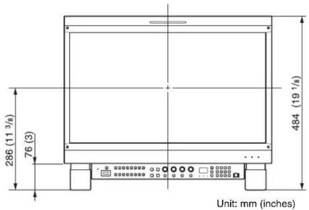
| Dimensions (with tilt unit) | 484 mm (width) x 286 mm (height) x 76 mm (depth) |
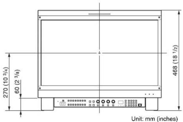
| Dimensions (without tilt unit) | 468 mm (width) x 270 mm (height) x 60 mm (depth) |
| Weight | Not specified (estimated ~5-8 kg) |
| Main Material | Metal and plastic |
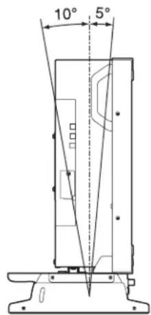
| Main Functions | Assembly of monitor and control unit, tilt 5° forward and 10° backward, height adjustment (with/without tilt unit) |
| Compatibility | Sony BVM-E251 monitor, Sony BKM-17R control unit |
| Power Supply | Not applicable (base does not require power; connection cable provided for DC 12V and LAN between monitor and control unit) |
| Package Contents | Right base (1), left base (1), rear crossbar (1), top right and left covers (1 each), bottom right and left covers (1 each), joints (2), screws A 3×8 (12), screws B 4×8 (16), screws C 5×10 (2), connection cable (1) |
| Maintenance and Cleaning | Clean with a soft, dry cloth; store removed screws carefully; wear protective gloves when handling |
| Safety | Read precautions carefully: use two people for assembly, do not step on the base, place on a stable surface, do not touch protruding parts without gloves, check tightness of tilt screws |
| Spare Parts and Repairability | Screws, covers, and connection cable are available as spare parts; the base is not user-serviceable |
| General Information | Warranty: see Sony terms; no liability for indirect damages; manual available in multiple languages |
Frequently Asked Questions - BKM-37H SONY
User questions about BKM-37H SONY
0 question about this device. Answer the ones you know or ask your own.
Ask a new question about this device
Download the instructions for your Other computer accessories in PDF format for free! Find your manual BKM-37H - SONY and take your electronic device back in hand. On this page are published all the documents necessary for the use of your device. BKM-37H by SONY.
USER MANUAL BKM-37H SONY
Japanese/English/French/German/Italian/Spanish
Simplified Chinese/Traditional Chinese/Korean
1st Edition (Revised 5)
安全のために
警告表示の意味
natural_image
Isometric line drawing of a rectangular electronic device with multiple circular components and mounting holes (no text or symbols)コントロールユニット
natural_image
Technical line drawing of a mechanical bracket assembly with mounting holes and mounting fasteners (no text or symbols)natural_image
Technical line drawing of a mechanical bracket assembly with mounting holes and internal components (no text or symbols)Before operating the unit, please read this manual thoroughly and retain it for future reference.
Table of Contents
Precautions 13
Overview 13
Features....13
Components....14
Assembly 15
Joining the Monitor and the Control Unit ....15
Tilting the monitor....17
Joining the Monitor ....18
Lowering the Height....18
Note
Always verify that the unit is operating properly before use. SONY WILL NOT BE LIABLE FOR DAMAGES OF ANY KIND INCLUDING, BUT NOT LIMITED TO, COMPENSATION OR REIMBURSEMENT ON ACCOUNT OF THE LOSS OF PRESENT OR PROSPECTIVE PROFITS DUE TO FAILURE OF THIS UNIT, EITHER DURING THE WARRANTY PERIOD OR AFTER EXPIRATION OF THE WARRANTY, OR FOR ANY OTHER REASON WHATSOEVER.
Precautions
- When you assemble the attachment stand, turn off the monitor power before unplugging the cable. If you attach the attachment stand with the monitor power on, the cable may become trapped between the monitor and the attachment stand and this may lead to electric shock.
- Join the monitor and the control unit with the help of another person to avoid injury.
- Install the attachment stand on a steady table. If the attachment stand is installed on a wobbly or sloping surface, the monitor may drop down and you may get injured. Make sure that the installation location is sufficiently strong.
- The use of other screws may lead to injury because they may loosen or fall out.
- Do not attach the attachment stand to the units other than those specified. If you do, the monitor may drop down and you may get injured.
- When you tilt the monitor, hold the top and the bottom of the monitor to avoid injury. If you do not hold the monitor properly, the monitor may drop down and you may trap your fingers in the attachment stand.
- Do not climb on the attachment stand or place anything heavy on it, as this may cause you to fall and injure yourself or the monitor to crash to the floor.
- Do not touch any sharp points of the attachment stand with bare hands. When you unpack, carry, attach and disassemble the attachment stand, wear protective gloves to avoid injury.
- Put on the side covers so that you may not trap your fingers in the movable parts.
- When you attach the attachment stand, be sure to secure the tilting screws on both sides of the attachment stand. If the tilting screws are not secured tightly, the monitor may move suddenly and you may get injured.
Overview
Features
The BKM-37H Controller Attachment Stand is a tilt stand for joining a BVM-E251 and a BKM-17R Monitor Control Unit.
Joining the monitor and the control unit
The BKM-37H joins the monitor and the BKM-17R control unit. The attachment stand is also usable as a tilt stand for the monitor even if the BKM-17R is not attached.
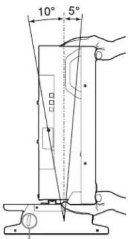
Tilting the monitor
The monitor can tilt between 5^ forward and 10^ backward when the attachment stand is attached.
Raising and lowering the height
Removal of the tilt unit pre-installed on the attachment stand allows the installation height to be lowered.
For removing the tilt unit, see “Lowering the Height” (page 18).
When the tilt unit is attached
When the tilt unit is removed
Components
The BKM-37H consists of the following components. Make sure that you have all the components before beginning assembly.
| Stand (right) (1) | 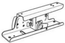 |
| Stand (left) (1) | 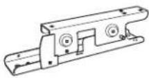 |
| Rear stay (1) | 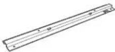 |
| Cover (upper) (right) (1) | 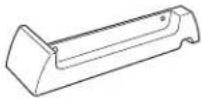 |
| Cover (upper) (left) (1) | 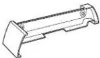 |
| Cover (lower) (right) (1) | 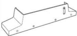 |
| Cover (lower) (left) (1) | 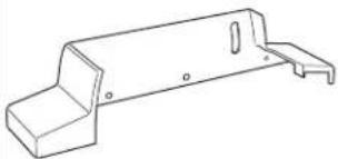 |
| Joints (2) | 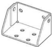 |
| Screws A (3 × 8) (12) |  |
| Screws B (4 × 8) (16) | 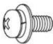 |
| Screws C (5 × 10) (2) |  |
| Connecting cable (1) | 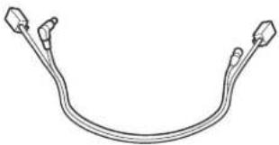 |
Assembly
Joining the Monitor and the Control Unit
You can join a control unit to a monitor using the attachment stand.
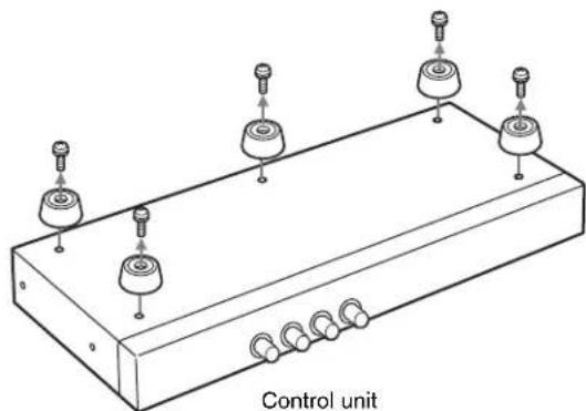
1 Remove the five legs from the bottom of the control unit.
natural_image
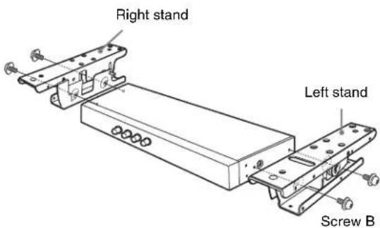
Technical line drawing of a control unit with multiple sensor components and coiled connections (no text or symbols)2 Attach the right stand and left stand to the sides of the control unit using four screws B (4 × 8).
Use two screws B for each stand.
3 Remove the four legs from the bottom of the monitor and the screws on the left and right sides from the rear of the monitor.
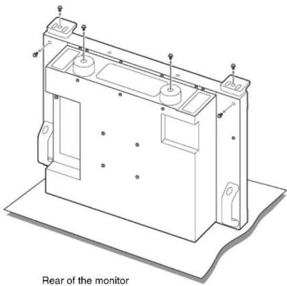
natural_image
Technical line drawing of a mechanical enclosure with mounting brackets and mounting holes, labeled 'Rear of the monitor' (no other text or symbols)Note
Place the monitor flat on a soft cloth.
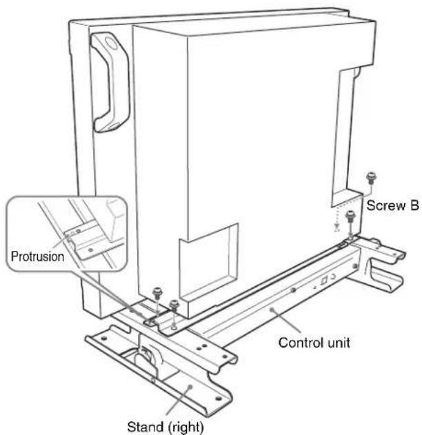
4 Place the rear stay on the monitor and assemble using two screws B (4 × 8).

5
Place the monitor on the control unit with the stands attached. Attach the monitor to the stands using four screws B (4 × 8), adjusting the positions of the screw holes of the rear stays and control unit.
Place the protrusion of the control unit into the hole of the rear stay as shown.
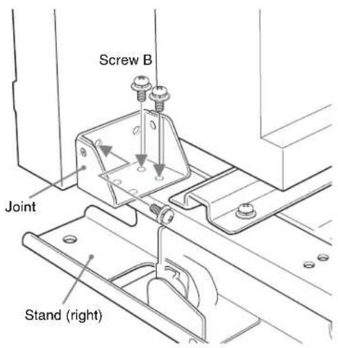
6
Place the joint on the right stand, and fix the right stand on the rear (right side) of the monitor using three screws B (4 × 8).
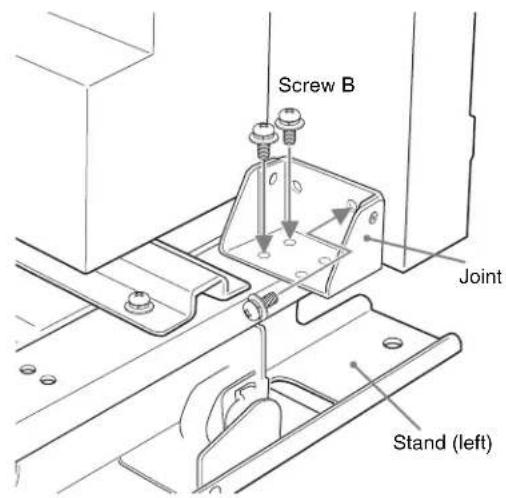
7
Place the joint on the left stand, and fix the left stand on the rear (left side) of the monitor using three screws B (4× 8) .
8
Attach the right upper cover and left upper cover to the stands using two screws A (3 × 8) each.
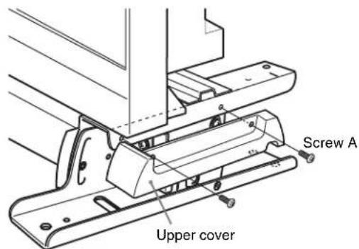
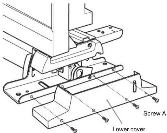
9
Attach the right lower cover and left lower cover to the stands using four screws A (3 × 8) each.
When the tilt unit is attached
Put the cover over the stand from above.
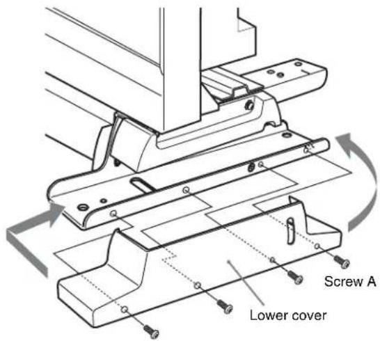
When the tilt unit is removed
First put the front of the cover over the stand, then fit the back of the cover while bending it outward.
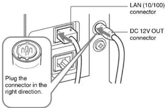
10 Connect the supplied connecting cable to the DC 12V and LAN (10/100) connectors on the rear panel of the control unit.
Note
Plug the connector of the DC cable (L-shaped) to the DC 12V connector.
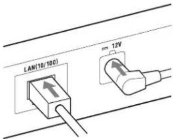
11 Plug the connecting cable into the DC 12V OUT and LAN (10/100) connectors on the rear panel of the monitor.
Note
When connecting the cable into the DC 12V OUT connector, be sure to plug the connector of the cable into the DC 12V OUT connector on the monitor in the right direction.
Tilting the monitor
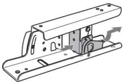
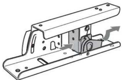
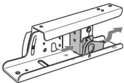
Loosen the tilting screw located inside the cover of the right stand and that of the left stand, and then tilt the monitor by holding the top of the monitor and the bottom of the monitor or control unit. Be sure to secure the tilting screws after tilting.
Tilting screw
Joining the Monitor
Even when the control unit is not joined to the monitor, the attachment stand can be attached to the monitor alone. For assembly, see steps 3 (page 15) to 9 (page 16) of "Joining the Monitor and the Control Unit".
Lowering the Height
The installation height of the attachment stand can be lowered when you remove the tilt units pre-installed on the right stand and the left stand. Remove the tilt units before the control unit is joined to the monitor.
Note
After the tilt units are removed, the monitor cannot tilt.
1 Loosen the tilting screws on the right stand and left stand.
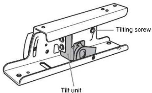
2 Remove seven screws from each of the right stand and left stand.
natural_image
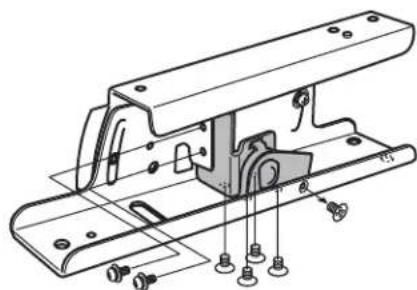
Technical line drawing of a mechanical bracket assembly with mounting holes and mounting fasteners (no text or symbols)3 Remove the tilt units from the right stand and left stand.
natural_image
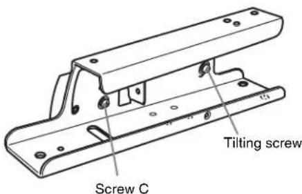
Technical line drawing of a mechanical bracket assembly with mounting holes and internal components (no text or symbols)4 Secure the supplied screw C (5 × 10) on each stand, and then secure the tilting screws.
Raising the Height of the attachment stand
Follow steps 1 to 4 in "Lowering the Height" in reverse order.
Note
Store the removed screws carefully for future use.
Français
Précautions ......20
Présentation....20
natural_image
Technical line drawing of a mechanical enclosure with mounting holes and internal components (no text or symbols)Remarque
natural_image
Technical line drawing of a mechanical bracket assembly with mounting holes and mounting feet (no text or symbols)natural_image
Technical line drawing of a mechanical bracket assembly with mounting holes and internal components (no text or symbols)natural_image
Technical line drawing of a Steuergerät electronic device with multiple ports and mounting holes (no text or symbols on components)natural_image
Technical line drawing of a mechanical enclosure with mounting holes and internal components (no text or symbols)Hinweis
natural_image
Technical line drawing of a mechanical bracket assembly with mounting holes and bolts (no text or symbols)natural_image
Technical line drawing of a mechanical bracket assembly with mounting holes and internal components (no text or symbols)natural_image
Technical diagram of a control panel with multiple adjustment knobs and a base, labeled 'Unità di controllo' (no other text or symbols)natural_image
Technical line drawing of a mechanical assembly with mounting holes and a central bracket (no text or symbols)natural_image
Technical line drawing of a mechanical bracket assembly with mounting holes and internal components (no text or symbols)natural_image
Technical line drawing of a control panel with multiple adjustment knobs and coiled components (no text or symbols)natural_image
Technical line drawing of a mechanical bracket assembly with mounting holes and fasteners (no text or symbols)natural_image
Technical line drawing of a mechanical bracket assembly with mounting holes and internal components (no text or symbols)natural_image
Technical line drawing of a mechanical bracket assembly with mounting holes and bolts (no text or symbols)3 从右支座和左支座上拆下倾斜装置。
natural_image
Technical line drawing of a mechanical bracket assembly with mounting holes and internal components (no text or symbols)natural_image
Technical line drawing of a mechanical assembly with mounting holes and bolts (no text or symbols)3 將右側和左側底座上的傾斜元件拆下。
natural_image
Technical line drawing of a mechanical bracket assembly with mounting holes and internal components (no text or symbols)natural_image
Isometric line drawing of a rectangular electronic device with multiple circular components and mounting holes (no text or symbols)natural_image
Technical line drawing of a mechanical housing component with mounting holes and internal compartments (no text or symbols)참고
natural_image
Technical line drawing of a mechanical assembly with mounting holes and bolts (no text or symbols)natural_image
Technical line drawing of a mechanical bracket assembly with mounting holes and internal components (no text or symbols)The material contained in this manual consists of information that is the property of Sony Corporation and is intended solely for use by the purchasers of the equipment described in this manual.
Sony Corporation expressly prohibits the duplication of any portion of this manual or the use thereof for any purpose other than the operation or maintenance of the equipment described in this manual without the express written permission of Sony Corporation.
For Customer in China

- 安全のために
- 警告表示の意味
- Table of Contents
- Note
- Precautions
- Overview
- Features
- Joining the monitor and the control unit
- Tilting the monitor
- Raising and lowering the height
- Components
- Assembly
- When the tilt unit is attached
- When the tilt unit is removed
- Joining the Monitor
- Lowering the Height
- Français
- Remarque
- Hinweis
- 참고
Brand : SONY
Model : BKM-37H
Category : Other computer accessories