Profiline 505T - Sprayer GLORIA - Free user manual and instructions
Find the device manual for free Profiline 505T GLORIA in PDF.

User questions about Profiline 505T GLORIA
0 question about this device. Answer the ones you know or ask your own.
Ask a new question about this device
Download the instructions for your Sprayer in PDF format for free! Find your manual Profiline 505T - GLORIA and take your electronic device back in hand. On this page are published all the documents necessary for the use of your device. Profiline 505T by GLORIA.
USER MANUAL Profiline 505T GLORIA
natural_image
Icon of an open book inside a black circle with a white border (no text or symbols)410 T*, 410 TRK*, 510 T*
* mit BBA-Zulassung
405 T, 505 T
natural_image
Blank white page with a curled corner corner, no text or symbols present.
5 L. 405 T / 505 T
natural_image
3D rendered mechanical component with directional arrows indicating movement or force (no text or symbols)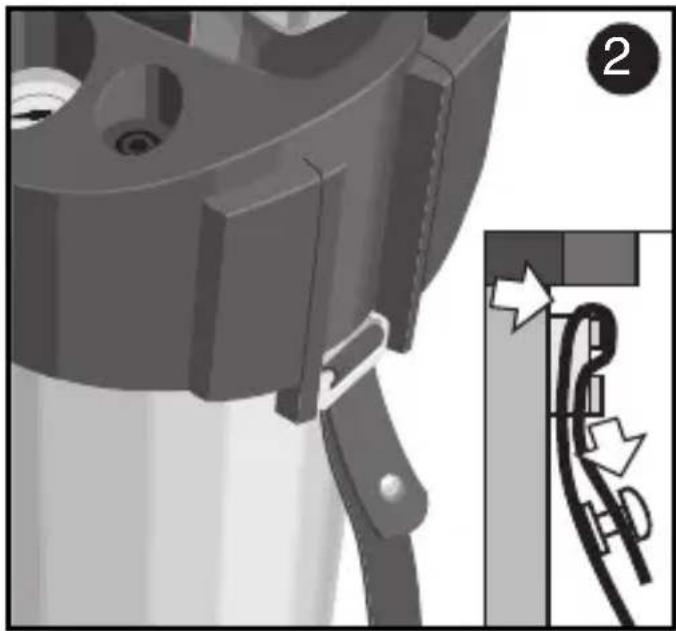
natural_image
Mechanical assembly diagram showing a component with mounting holes and a close-up of a cable being inserted (no text or symbols present)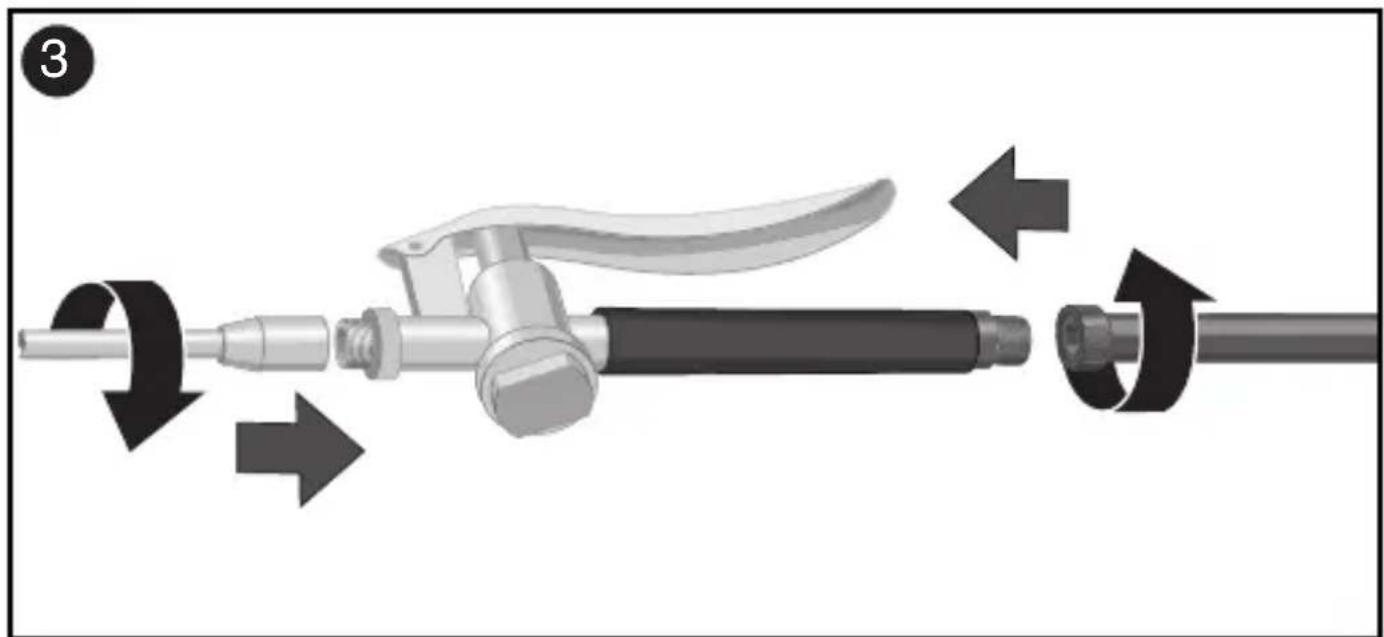
natural_image
Mechanical assembly diagram showing a tool with directional arrows indicating motion (no text or symbols)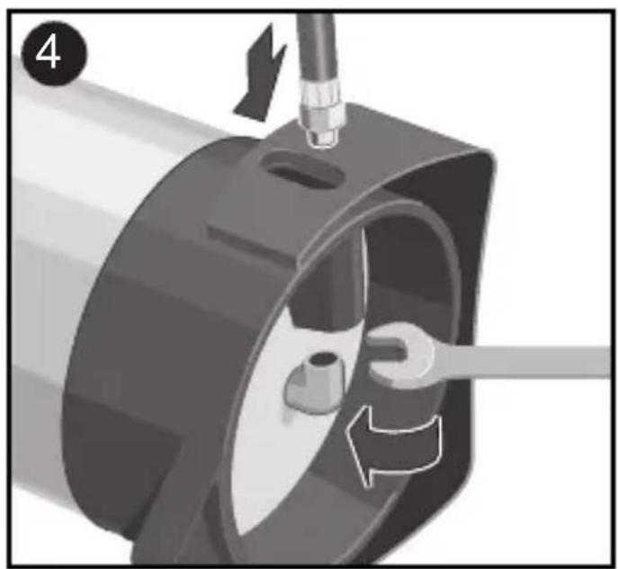
natural_image
Mechanical component diagram showing a rotating wheel with directional arrows indicating motion (no text or symbols)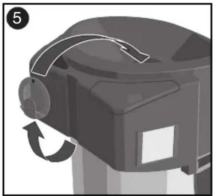
natural_image
Mechanical component with curved arrow indicating rotation or motion (no text or symbols)
5 L. 405 T / 505 T
natural_image
Mechanical component with a downward arrow indicating a process or motion, no visible text or symbols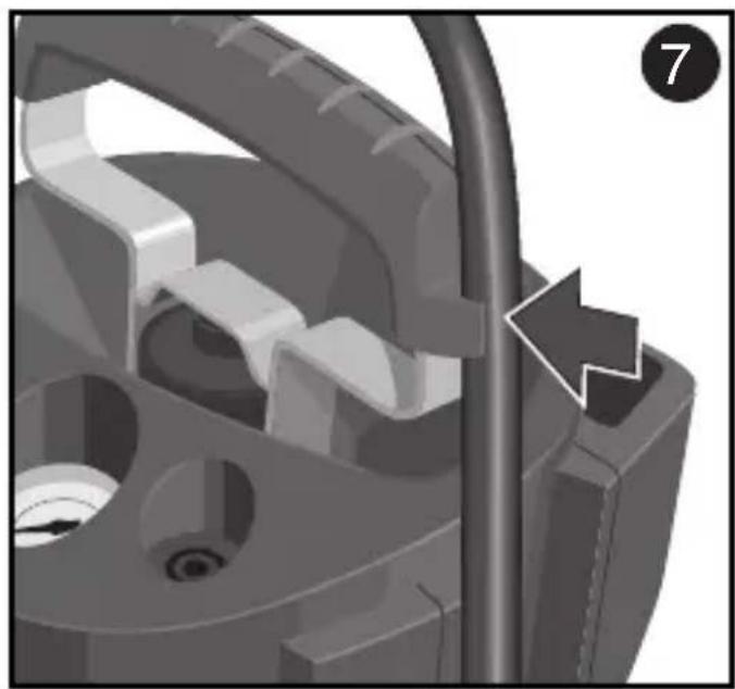
natural_image
Mechanical component with internal gear and pipe assembly (no visible text or symbols)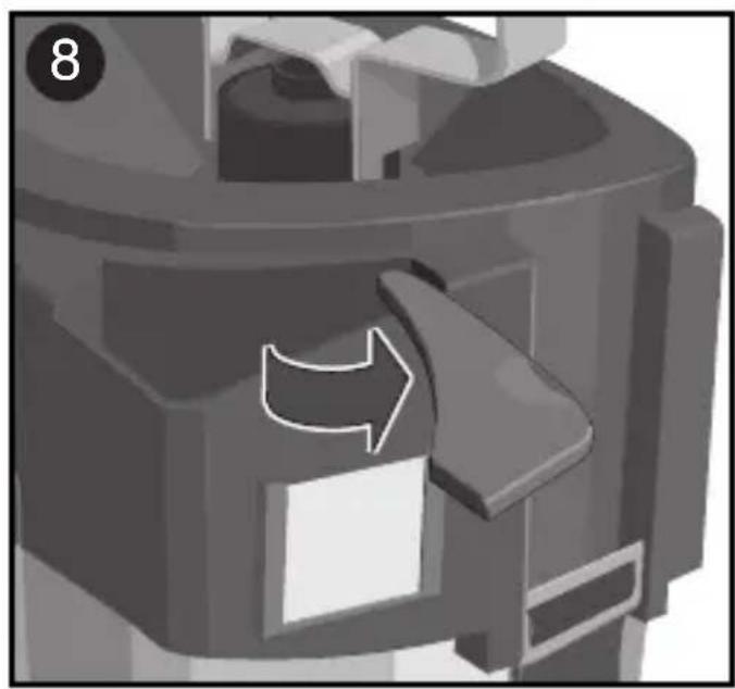
natural_image
Close-up of a mechanical component with a curved arrow indicating direction (no text or symbols)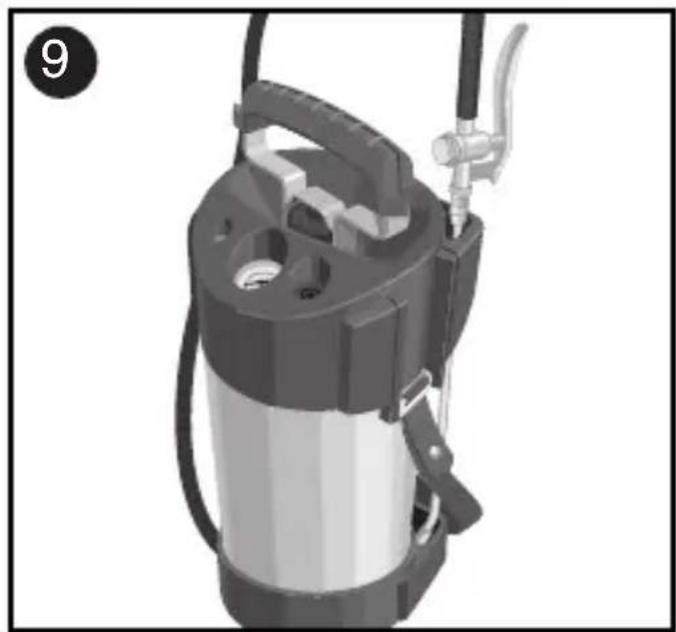
natural_image
3D rendering of a portable water purifier with attached tubing and valve (no text or symbols visible)
natural_image
Mechanical assembly diagram showing a component with a highlighted section and magnified detail (no text or symbols)
10 L. 410 T / 410 TRK / 510 T
natural_image
Mechanical component diagram showing a lever mechanism with arrows indicating motion (no text or symbols present)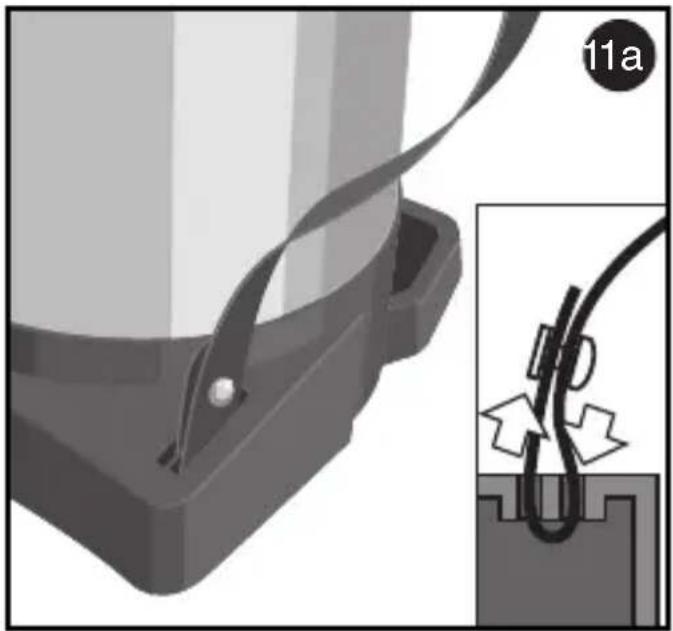
natural_image
Mechanical assembly diagram showing a clamping device with attached cable and a close-up of a wire being inserted (no text or symbols)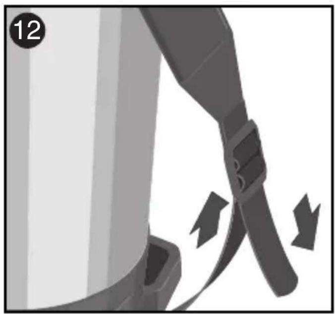
natural_image
Close-up of a mechanical belt buckle with directional arrows indicating motion (no text or symbols)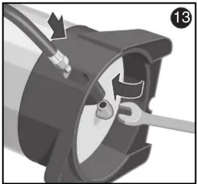
natural_image
Mechanical component diagram showing a rotating fan with internal blades and a cable inserted (no text or symbols)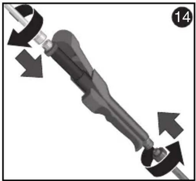
natural_image
Mechanical component diagram showing a shaft and lever with directional arrows indicating motion (no text or symbols)

10 L. 410 T / 410 TRK / 510 T
natural_image
Mechanical assembly diagram showing a component with multiple slots and a magnified inset (no text or symbols)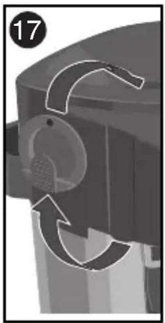
natural_image
Mechanical component diagram showing a rotating mechanism with curved arrows indicating motion (no text or symbols)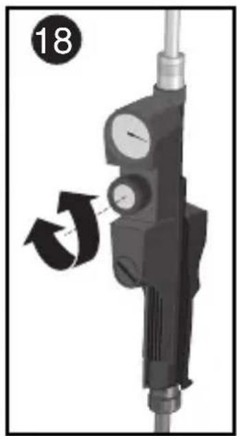
natural_image
Mechanical device with gauges and adjustment knob, no visible text or symbols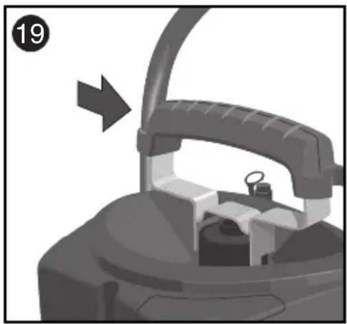
natural_image
Close-up of a hairdryer with a curved handle and control panel, showing a mechanical component (no text or symbols visible)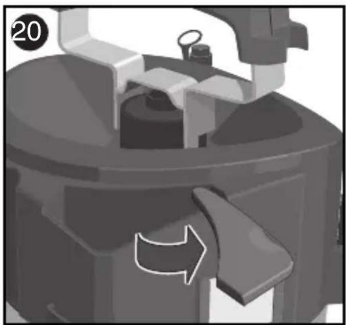
natural_image
Mechanical component with directional arrow indicating motion (no text or symbols)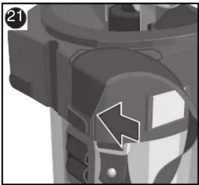
natural_image
Close-up of a mechanical component with a white arrow symbol pointing to a specific part (no text or symbols present)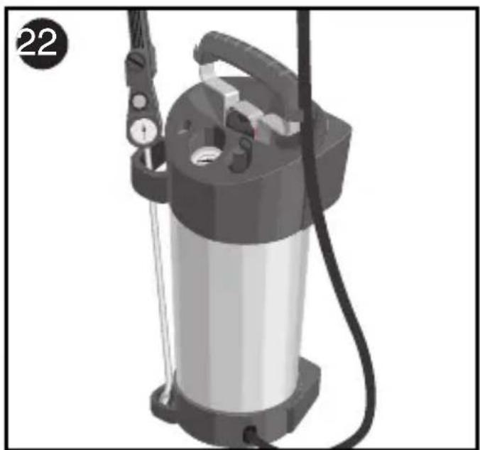
natural_image
3D rendering of a spray gun with attached control panel and hose (no text or symbols visible)
410 TRK
natural_image
Mechanical assembly diagram showing a tire and gasket with a hammer inserted, no text or symbols present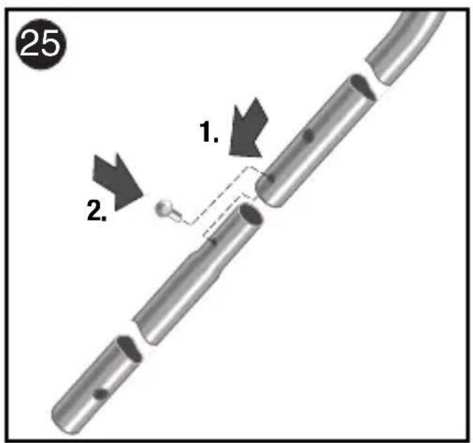
natural_image
Industrial water purifier with handle and control panel (no visible text or symbols)Technische Daten
Total tank capacity in litres 8 13.7 13.7 8 13.7
Max. operating pressure 6 bar x x x x x
Max. operating temperature
0^ to +50^ X X X X X
Full pressure change 0 bar to 6 bar max. 5000 load cycles
Empty weight (kg) 4.4 5.6 7.0 4.35 5.5
Transport cart - - x - -
Compressor connection - - x - -
Spray tube holder x x x x x
Pressure relief valve X X X X X
Backrest - X X - X
Safety features
Nozzle: standard
Spray pattern / angle of spray
Hollow cone / 55° (G-H-49-55) x x x x x
Fan jet / 80° - - - - -
Max. spray capacity 1 l/min. 1 l/min. 1 l/min. 1 l/min. 1 l/min.
Recoil at the nozzle < 5N < 5N < 5N < 5N < 5N
Tank material:
- Steel, coated internally x x x - -
- Stainless steel - - - x x
Pump material: brass brass brass brass brass
Mesh size of filter in 0.9 mm 0.9 mm 0.9 mm 0.9 mm 0.9 mm
quick-connecting valve (Caution: when using other nozzles, heed filter mesh size)
Residue when emptied < 30 ml < 30 ml < 30 ml < 30 ml < 30 ml
horizontally
Features 410T, 410 TRK, 510T:
Safety valve with pressure relief valve, manometer
X X X X X
- - - - -
1 l/min. 1 l/min. 1 l/min. 1 l/min. 1 l/min.
<5N <5N <5N <5N <5N
X X X - -
- - - X X
brass brass brass brass brass
0.9 mm 0.9 mm 0.9 mm 0.9 mm 0.9 mm
(Caution: when using other nozzles, heed filter mesh size)
<30 ml <30 ml <30 ml <30 ml <30 ml
All plastic quick closure valve with integrated pressure regulator, manometer and spare nozzle retainer and 2 washers
Optional Accessories, see separate sheet 976 559
<30ml <30ml <30ml <30ml <30ml
5 litran 10 litran 10 litran 5 litran 10 litran
| 5 | 1 | 0 | 1 | 0 | 5 |
| 8 13,7 | 13,7 | 8 13,7 | |||
| x | x | x | x | x | |
| x | x | x | x | x | |
| maks. kuormituksen muutos 5000 | |||||
| 4,4 | 5,6 | 7,0 | 4,35 | 5,5 | |
| - | - | x | - | - | |
| - | - | x | - | - | |
| x | x | x | x | x | |
| xxxxx | |||||
| - | x x - | x | |||
Important Safety Precautions 27
Getting Started 28
Spraying 30
Assembly transport cart 31
Emptying and Servicing 31
Tips 32
Troubleshooting 107
Declaration of conformity 118
Important Safety Precautions
Repairs to house and garden equipment should only be carried out by Service Stations. Order spare parts from your authorised dealer. If the required parts are not in stock, he will procure them for you as quickly as possible
● These pump spray units are intended for use with pesticides. They may only be used with officially approved pesticides (for Group 2 fluids in accordance with Directive 97/23/EC). Please pay particular attention to the following safety precautions and instructions for first-time use.
● The 10 litre units are especially suited for use with officially approved pesticides.
● Before each use, check that the safety valve and pressure relief valve are functioning properly (see: Getting Started).
- Do not store the unit in barns or stables where cattle are kept as the ammonia vapours may cause cracks to form in the brass parts; do not fill tank with solutions containing nitrogen or phosphate.
- Do not leave the unit under pressure unnecessarily for longer periods of time.
● Protect the unit against prolonged exposure to the sun and against frost.
- As a precautionary measure, we recommend that the high pressure spray unit be subjected to a particularly thorough inspection every five years, preferably by the manufacturer. Repairs to the tank are not permitted.
- Follow the instructions provided by the manufacturer of the agent being sprayed. If necessary wear protective clothing.
- Do not mix more of the spray mixture than required. Do not pour the residue down the drain. Instead, dilute residue 1:10 and spray on plants.
- When handling pesticides and other chemicals, remove protective clothing and wash hands and face carefully (rinse mouth out) before eating, drinking or smoking.
- Do not try to clear blocked nozzles by blowing into them with your mouth.
- When unscrewing the spray tubes, keep the end pointed away from you.
- For safety reasons, do not spray explosive agents, highly corrosive fluids, disinfectants and impregnating agents. This applies to all the above models.
● Caution!
Please note that under product liability law we are not liable for damage resulting from the use of our product if such damage was caused by improper repair or if original replacement parts are not used to replace defective or worn out parts and the repair was not carried out by our Customer Service or by an authorised service technician. This also applies to accessories.
● The service life of the unit must be determined by the operator based on a risk assessment, taking into account the operating conditions. Due to possible material fatigue, we recommend that a service life of 10 years is not exceeded.
Getting Started

5 litre units
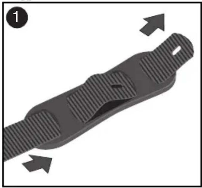
Fitting the carrying straps
Fig. 1
● Fitting the shoulder pads
Fig. 2
● Fitting the carrying straps
Fitting the spraying lance
Fig. 3
- Screw spray tube and spraying lance to the quick closure valve. Implement a quick pressure test with water.
Fitting the spray tube
Fig. 4
● Lay tank on its side and screw the spray tube onto the tank.
10 litre units
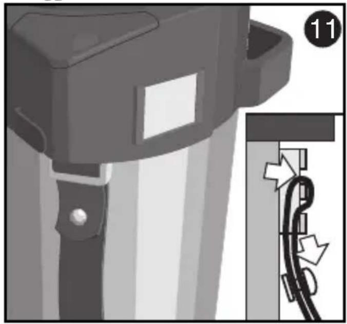
Fitting the carrying straps
Fig. 11
Fitting the top carrying strap
Fig. 11a
Fitting the bottom carrying strap
Fig. 12
Adjusting the carrying straps
● The carrying straps are adjusted by pulling on the strap ends after the unit has been positioned on the back. The carrying straps can be lengthened by pulling on the adjusters.
Fitting the spray tube
Fig. 13
● Lay tank on its side and screw the spray tube onto the tank.
Fitting the spraying lance
Fig. 14
- Screw spray tube and spraying lance to the quick closure valve. Implement a quick pressure test with water.
5/10 litre units
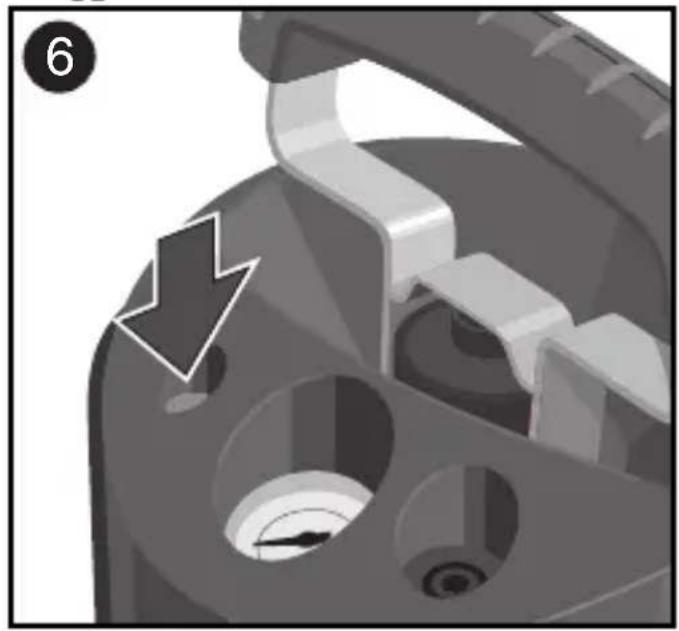
Check safety valve
Fig. / 6 15
- Check the safety valve each time before you use the unit! Insert the pump and screw it in. Operate the pump until the pressure gauge shows no further increase in pressure (the safety valve blows off the excess pressure).
● Caution! Fig. 15a
Some types of unit are equipped with a connection for an air compressor.
The following must be observed in such a case.
- Compressor boost pressure or compressed air supply secured onto max. 6 bar.
- Ensure the pump is in the locked position before pressurizing.
- Do not exceed the maximum filling level.
- The non-return valve in the compressor connection must not be removed to depressurize the tank.
Fill tank
- Remove the pump by turning it to the left. To do this, first release the piston rod, turn it 180° and transfer the screw force via the back of the locking pins on the pump housing.
- Attach pump to filling hopper.
5 litre units – Fig.
10
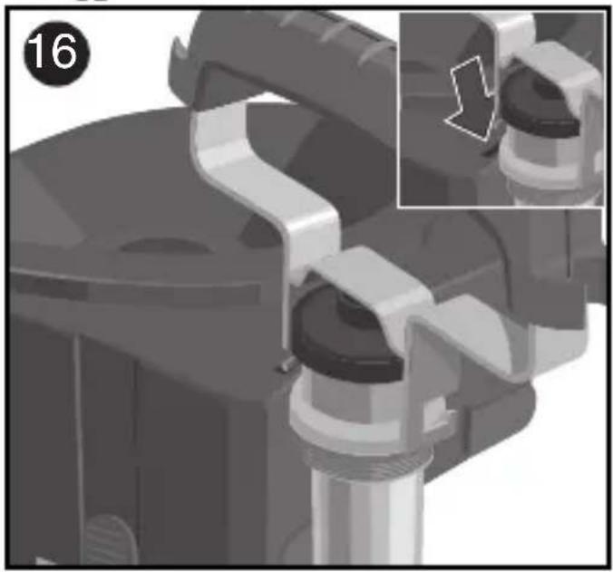
10 litre units – Fig.
16
● Fill tank. Caution! Note maximum fill level based on technical data (see supplementary sheet), safety instructions and permissible materials.
● Note: Filling strainer!
Use the supplied filling strainer for filling the tank. The filling strainer should be used for pre-filtration, especially when spraying agents are used, particularly when powder-based concentrates are used.
5 litre units – Fig.
5
10 litre units – Fig.
17
● To check filling level: Insert a rod through the filler opening to the bottom of the tank. Mark the top edge of the filler funnel on the rod. Withdraw the rod from the tank and hold it up against the litre scale on the outside, making sure that the mark on the rod lines up with the top edge of the filler funnel. The liquid level marked on the rod can be read off on the litre scale.
- Insert the pump and screw into position.
● Operate the pump until an operating pressure of 6 bar (red line on manometer) in the tank has been reached. - Spray compound dosage: Observe the instructions of the spray compound manufacturer (see sample computation)! At the time of production of this unit, the manufacturer was not aware of any damaging effects of the pesticides permitted by the German Federal Biological Institute (BBA) on the materials of which the unit is made.
Sample computation for checking and determining dosage of spray compound
Bases:
Spraying pressure 1.5 bar
Nozzle 1 mm hollow cone
Spraying height 50 cm
Dosage 0.5 % (see pesticide
manufacturer's instructions)
This means:
Quantity required 0.42 l/min
Spraying width 50 cm
Angle of spray 55°
Quantity of spray compound
(see pesticide manufacturer's instructions)
To mix 1 I spray compound:
1 l water + 5 ml compound
(5 ml = 0.5 % of 1 litre)
With a spraying width of 50 cm, a length of 2 m equals a sprayed area of 1 m ^4 .
Speed of spraying:
Quantity sprayed per minute x distance Quantity of spray per m ^2
$$ \frac {0 . 4 2 \mathrm{l} \times 2 \mathrm{m}}{\min . \times 0 . 0 6 \mathrm{l}} = 1 4 \mathrm{m/min}. $$
The figures on which this sample computation of the dosage and the quantity of spray compound required per m^2 are based have been assumed for that purpose. When using the sample computation, the figures given by the manufacturer of the respective spray compound must be used. If other nozzles are used, the appropriate technical data must be taken from the separate sheet 976 559 (Optional Accessories and Nozzle Table) ** and used in the computation.
Spraying
● To obtain as even a spray pressure and as long a spray cycle as possible, set the pressure regulator on the quick close valve (10 litre units only) at the minimum permissible pressure e.g. 1.5 bar (see
Fig.)18
● To start the spraying process push the operating lever on the quick close valve down. Releasing the operating lever will stop the spraying process immediately.
- If the pressure in the tank falls below the minimum permissible pressure, work the pump a little to ensure an even spray. The optimum spraying pressure for the 1 mm hollow cone spray is between 1.5 and 3 bar.
- When spraying, ensure that the plants are wetted evenly.
● Pay attention to the direction of the wind!
Do not spray into the wind.
● The optimum distance from the nozzle to the plant being sprayed is between 40 and 50 cm.
- When using special spraying lances (extension lances, wide spray lances etc.), set the pressure higher on the pressure regulator.
See separate sheet 976 559 (Optional Accessories and Nozzle Table)\*\*
Assembly transport cart\*
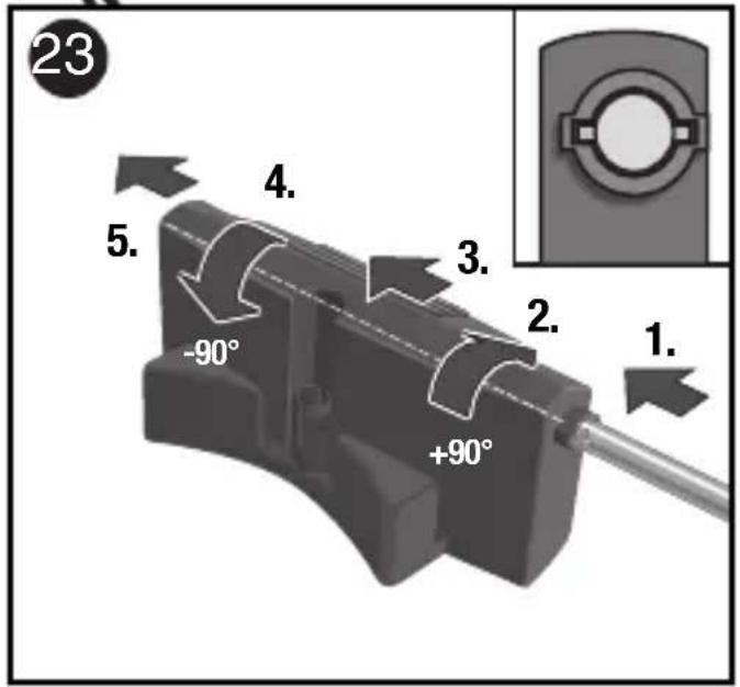
Mounting the axle
Fig. 23
● 1. Insert transport cart axle in case part. The axle noses must be aligned with the notches on the case part so that the axle can be inserted.
2. Once the axle noses are inserted, the axle must be rotated through 90^ .
3. Now push the axle through to the stop on the opposite side.
4. Rotate the axle again through 90^ .
5. Now push the axle so far that the noses on the left and right sides sit in the notches of the case part.
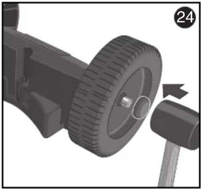
Mounting the wheels
Fig. 24
- Push the wheels onto the axle on the left and right sides. Place a snap-on fastener on the axle end and push it onto the axle using a plastic hammer. The wheels must be able to turn freely.
Note! Snap-on fasteners can only be removed by destroying them
Mounting the handle
Fig. 25
- Attach the upper curved rod and screw together with the straight rod piece to form a complete handle.
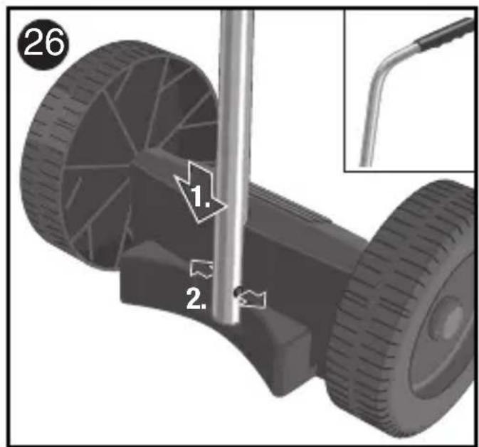
Fig.
26
● 1. Position the handle on the pin of the case part. Attention! The handle must point backwards as illustrated.
2. Now push the handle down to the stop on the pin, the detents must engage in both holes.
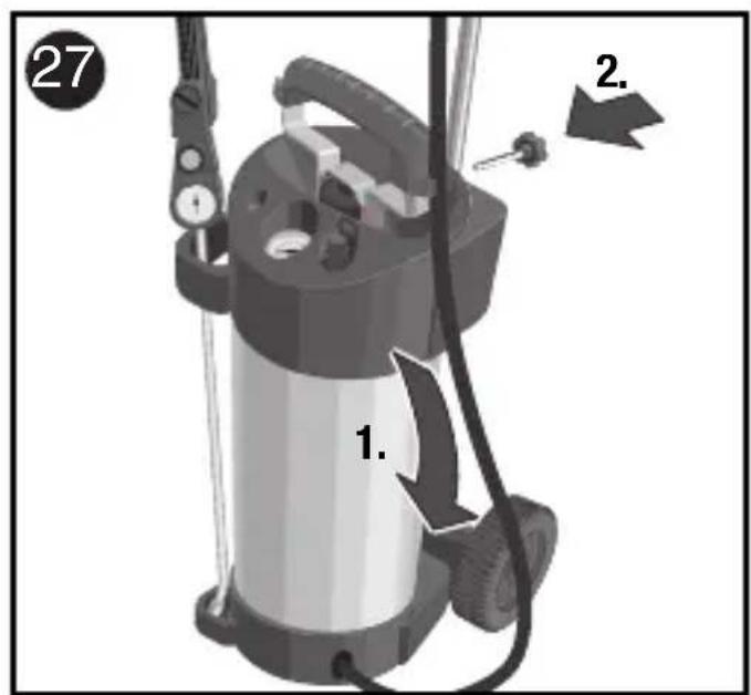
Position and mount the spraying unit
Fig.
27
● 1. Position the spraying unit as illustrated.
2. Screw spraying unit to handle.
* Available as an accessory or included in the scope of delivery in units with compressor connections.
Emptying and Servicing
● Operate the pressure relief valve (red button) until the unit is no longer under pressure.
- Open the pump carefully, at first only a few turns to the left, to allow any compressed air still in the tank to escape. Only then should the pump be un-screwed completely and removed from the tank.
- Clean the unit thoroughly with water after each use, rinsing out several times, and leave open to dry, if possible hanging up with the opening pointing down.
● Store the unit in a depressurised condition.
● To clean the filter tube in the quick close valve:
a) quick close valve with metal operating lever:
- unscrew the handle on the quick close valve for cleaning.
b) plastic quick close valve with plastic operating lever:
- unscrew the quick close valve at the hose connecting socket for cleaning.
● The service life of the unit will be greatly extended by occasionally applying resin and acid-free grease to the sealing ring between the pump and the tank and to the inner O ring.
- To obtain optimum cleaning of the spray unit and to ensure that spray compound residues are neutralised, the use of Special Activated Charcoal is recommended – this can be obtained from the manufacturer.
- Use only original replacement parts for repairs.
● Repairs may only be implemented by the manufacturer's service stations.
- Important note: Undue strain caused by the mode of operation (including transport to site where used and storage when not in use), environmental influences (at the site where used and where stored when not in use), insufficient maintenance and care may lead to premature wear and tear of the unit. For this reason, always check the unit before use to make sure that it is in a safe and operable condition, at least, however, for outwardly recognisable signs of damage. To ensure continued safe operation of the unit, a technician, preferably from the manufacturer's service department,
should inspect the unit in the event of defects affecting safe operation, in particular, but at a minimum every five years.
The national regulations applicable at the place of use regarding safety at work and the national regulations applicable to the company must be complied with.
** The separate sheet "Optional Accessories and Nozzle Table" is only available in German and is not included with all models.
We reserve the right to make technical changes.
Tips
Tube fastening when in park position
5 litre units – Fig.
7
10 litre units - Fig.
19
● To keep the tubes close to the unit, they can be clipped onto the pump handle at the top.
Storage compartment
5 litre units – Fig.
8
10 litre units – Fig.
20
- Small or accessory components (e.g. spare seals or nozzles) can be kept in the storage compartment.
Clipping in the carrying straps (10 litre units only)
Fig. 21
● To protect the carrying straps against moisture or dirt or to avoid danger of trip-
ping over loose carrying straps, they can be clipped onto the rear of the unit.
Carrying or park position
5 litre units – Fig.
9
10 litre units – Fig.
22
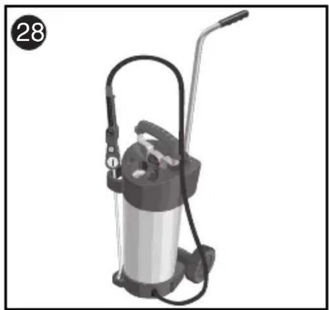
10 litre units with
transport cart – Fig.
28
● The spray lance should be positioned as shown in the spray lance holder when the unit is being transported or is not in use.
Table des matières
| Malfunction | Cause | Remedy |
| No pressure is built up in the tank when the pump is operated | Pump is not screwed tightly into the tankO ring where the pump is connected to the tank is defectiveO ring in the pump is defective | Screw pump in tightlyReplace O ringReplace O ring |
| The flexible hose is leaking | The flexible hose is not screwed securely into the tank | Tighten hose connection.Check pressure using water |
| The unit does not spray despite maximum pressure | The filter in the quick closure valve or the nozzle is clogged | Clean the filter and/or nozzle |
| The nozzle's spray pattern is not in order | The nozzle is partially clogged | Clean the nozzle |
Elimination des pannes
CE-statement of conformity for a module within the meaning of Art. 3, section 2 of the directive on pressurized equipment 97/23/EG
GLORIA
confirms that high performance spray units
Item No. 405....
410..., 411...
505..., 510...
certificate- No. (Module A1)
07202 1403 Z 0003 / 7 / D001
comply with the directive on pressurized equipment 97/23/EG and the recognized rules of technology.
The procedure for the statement of conformity for the module and for the tank is based on module A1 (Appendix III) of directive 97/23/EC.
Notified body, TÜV NORD Systems GmbH & Co. KG.
Witten, 01.02.10

Hans-Georg Wellerdiek · (Design Manager)
natural_image
Close-up of a fountain pen nib with metallic tip and black handle (no visible text or symbols)
natural_image
Close-up of a fountain pen nib with metallic tip and black handle (no visible text or symbols)Gloria Service Center
www.gloriagarten.de