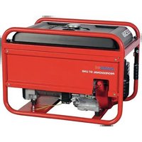
ESE 506 DHS-GT - Generator Endress - Free user manual and instructions
Find the device manual for free ESE 506 DHS-GT Endress in PDF.


User questions about ESE 506 DHS-GT Endress
0 question about this device. Answer the ones you know or ask your own.
Ask a new question about this device
Download the instructions for your Generator in PDF format for free! Find your manual ESE 506 DHS-GT - Endress and take your electronic device back in hand. On this page are published all the documents necessary for the use of your device. ESE 506 DHS-GT by Endress.
USER MANUAL ESE 506 DHS-GT Endress
natural_image
Red professional GT line equipment with visible internal components and branding (no readable text beyond branding)ESE 206 HS-GT
Artikel-Nr. 112300
ESE 406 HS-GT
Artikel-Nr. 112302
ESE 506 DHS-GT
Artikel-Nr. 112304
ESE 606 HS-GT ES
Artikel-Nr. 112307
ESE 606 DHS-GT ES
Artikel-Nr. 112308
ESE 306 HS-GT
Artikel-Nr. 112301
ESE 406 HS-GT ES
Artikel-Nr. 112306
ESE 606 HS-GT
Artikel-Nr. 112303
ESE 606 DHS-GT
Artikel-Nr. 112305
text_image
Labeled diagram of an orange portable power supply unit with numbered parts and warning labelstext_image
Safety warning symbols including checkmark, warning triangle, and exclamation mark on a wall-mounted deviceGerät tragen
natural_image
Illustration of a mechanical device with a warning sign and smoke, no text or symbols present.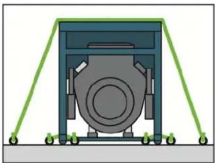
natural_image
Diagram of a mechanical device with green support frames and a central circular component (no text or symbols)text_image
Safety warning illustration showing fuel pump, no smoking symbol, and hazard warning symbol with explosion hazardnatural_image
Simple line drawing of a boat hull with an arrow indicating direction (no text or symbols)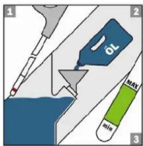
text_image
1 2 OL MAX min 3natural_image
Illustration of a hand reaching into a water drop onto a mechanical device with a warning symbol (no text or labels)natural_image
Close-up of a mechanical device with two blue electrical connectors and labeled buttons (no readable text or symbols)natural_image
Mechanical assembly diagram showing a key inserted into a component with a bolt and nut (no text or symbols)natural_image
Close-up of a red vehicle's engine compartment with visible warning signs and electrical components (no readable text or symbols)text_image
Close-up of industrial equipment with visible warning labels and safety symbols on a red framenatural_image
Close-up of a red tractor with visible exhaust pipe and control panel (no text or symbols)and subsequent modification and integrations et aux modifications successives at intégrations
measuring procedure according to ISO 3744 (part110)
procédé de repérage conformément à ISO 3744 (part110) el procedimiento de medición conforme a ISO 3744 (parte10)
conformity assessment procedure according to 2000/14/EC procedure VIII. (notified body)
procede d'evaluation de conformite 2000/14/EC procedure VIII. (organisme avise:)
Directorate General Environment
Unit C.1 "Air, Noise & Transport"
BU-9 06/204 - B-1049 Bruxelles
Belgium
verantwortlich
authorized by
le responsable
el responsable
natural_image
Red professional OT line portable electric transporter with black frame and wheels (no visible text or symbols)natural_image
Red professional gas turbine machine with visible internal components and branding (no text or symbols on the device body)ESE 206 HS-GT
Item No. 112300
ESE 406 HS-GT
Item No. 112302
ESE 506 DHS-GT
Item No. 112304
ESE 606 HS-GT ES
Item No. 112307
ESE 606 DHS-GT ES
Item No. 112308
ESE 306 HS-GT
Item No. 112301
ESE 406 HS-GT ES
Item No. 112306
ESE 606 HS-GT
Item No. 112303
ESE 606 DHS-GT
Item No. 112305
Date of issue May 2011
This documentation, including all of its parts, is protected by copyright. Any use or modification outside the restricted limits of the Copyright Act without the consent of ENDRESS Elektrogerätebau GmbH is forbidden and subject to penalty.
This applies in particular to copies, translations, microfilming, as well as storage and processing in electronic systems.
1 General information....5
1.1 Documentation and accessories ....6
1.2 Safety symbols....6
2 General Safety Regulations....7
2.1 Intended use....7
2.1.1 Intended use ....7
2.1.2 Foreseeable incorrect use or inappropriate handling ....8
2.1.3 Residual risks....9
2.2 Qualification and duties....11
2.3 Personal protective equipment....11
2.4 Danger zones and work areas....11
2.5 Labels on the generator....12
2.6 General safety instructions....14
3 Description....18
3.1 Function and mode of operation....19
4 Commissioning....20
4.1 Transporting the generator....20
4.2 Setting up the generator....21
4.3 Refuelling the generator 22
4.4 Fill the generator with engine oil....23
4.5 Starting the generator....25
4.6 Connecting appliances....28
4.7 Switching the generator off....29
4.8 Putting the generator out of service....30
5 Maintaining the generator ....34
5.1 Maintenance plan....34
5.2 Checking the electrical safety....35
6 Troubleshooting....36
7 Technical specifications....38
8 Warranty....41
9 Declaration of Conformity 42
1 General information

These operating instructions must be read carefully and understood before using the generator.
These operating instructions are intended to make you familiar with the basic operation of the generator.
These operating instructions contain important information for using the generator safely and appropriately.
Complying with this information helps to:
- avoid hazards
• reduce repair costs and downtime - increase the reliability and service life of the generator.
However, not only these operating instructions but also the laws, regulations, guidelines, and standards applicable in the country of use and at the site of operation must be observed.
These operating instructions only describe the generator operation.
The operating manual for the engine is an integral component of these instructions.
A copy of these operating instructions must be available to the operating personnel at all times.
1.1 Documentation and accessories
In addition to the operating manual there are also the following documents and standard accessories for the generator.
• Operating manual for the engine
• Warranty information for the engine
• Operating manual for the generator
1.2 Safety symbols
The safety symbol represents a source of danger.

General hazard
This warning sign indicates activities where several causes can lead to risks.
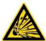
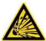
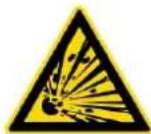
Potentially explosive materials
This warning symbol indicates activities during which there is an explosive hazard, possibly with lethal consequences.
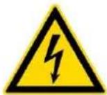
Warning of a dangerous electrical voltage
This warning symbol indicates activities during which there is the danger of electric shock, possibly with lethal consequences.

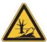
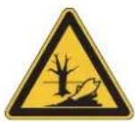
Warning of environmentally damaging substances
This warning symbol indicates activities, during which the environment could be endangered, possibly with catastrophic consequences.

Hot surfaces
This warning symbol indicates activities during which there is the danger of burns, possibly with lasting consequences.
2 General Safety Regulations

This section describes the basic safety regulations for operating the generator.
Whoever operates the generator or works with it must read this chapter and comply with its regulations in practice.
2.1 Intended use
The generator was in accordance with the accepted state of the art as well all valid safety regulations at the point in time of bringing it onto the market, when used as intended.
It was not possible to avoid foreseeable misuse or residual risks through design measures without limiting the intended functionality.
The information about risks is given using special warning signs either directly mounted on the generator and/or in the technical documentation.
2.1.1 Intended use
The generator produces electricity in place of the power grid, in order to supply a mobile distribution system.
The generator may only be used outdoors within the indicated voltage, output, and nominal rpm ranges (see model plate).
The generator may neither be connected to other energy distribution systems (e.g. public power supply) nor to other energy generation systems (e.g. other generators).
The generator may not be used in explosion-prone environments.
The generator may not be used in fire-prone environments.
The generator must be operated according to the specifications in the technical documentation.
Any non-intended use or any activity on the generator not described in these operating instructions is considered forbidden incorrect use outside the legal limits of the manufacturer's liability.
2.1.2 Foreseeable incorrect use or inappropriate handling
Foreseeable incorrect use or inappropriate handling of the generator nullifies the manufacturer's EC Declaration of Conformity and automatically thereby the operating licence.
Foreseeable incorrect use or inappropriate handling include:
• Operation in explosion-prone environments
• Operation in fire-prone environments
• Operation in confined areas
• Operation with direct contact with rain or falling snow
• Operation without the necessary safety redundancies
• Operation in existing power supply networks
• Refuelling when hot
• Refuelling during operation
- Spraying with high-pressure cleaners or fire-extinguishing equipment
• Operation with removed safety devices
• Non-compliance with maintenance intervals
- Failure to measure and test for early damage identification
- Failure to replace wearing parts
• Incorrectly performed maintenance or repair work
• Defectively performed maintenance or repair work
- Unintended use
2.1.3 Residual risks
The points analysed and evaluated before beginning the design and planning of the generator were the residual risks using a risk analysis tool.
Residual risks which cannot be avoided by implementing design measures during the whole life cycle of the generator can be:
- Risk of death
- Risk of injury
• Environmental hazard
• Material damage to the generator
• Material damage to other property
• Limited performance or functionality
You can avoid existing residual risks by observing and following these guidelines:
• The special warning notices on the generator
- The general safety instructions given in these operating instructions
- The specific warnings given in these operating instructions
Risk of death Risk of death to persons at the generator can be caused by:
- Incorrect use
- Inappropriate handling
- Missing protective equipment
• Defective or damaged electrical components - Touching the generator with wet hands
- Fuel vapours
- Engine exhaust
Risk of injury Risk of injury to persons at the generator can be caused by:
- Inappropriate handling
- Transport
- Hot components
• Recoiling starter rope on the engine
Environmental hazard
Environmental hazards involving the generator may be caused by:
- Inappropriate handling
- Operating fluids (fuel, lubricants, engine oil, etc.)
• Exhaust gas emission - Noise emission
- Fire hazard
Material damage to the generator
Material damage to the generator can occur through:
- Inappropriate handling
• Overloading
• Overheating
• Too low/high oil level of the engine - Non-compliance with the operating and maintenance specifications
• Unsuitable operating fluids
Material damage to other property
Material damage to other property in the operating range of the generator can occur through:
• Inappropriate handling
• An over and/or undervoltage
Limits to performance or functionality
The generator's performance or functionality can be limited by:
- Inappropriate handling
• Inappropriate maintenance or repair work
• Unsuitable operating fluids - An installation altitude greater than 100 metres above sea level
• An ambient temperature exceeding 25^ C
• Too large a distribution network configuration
2.2 Qualification and duties
All work performed on the generator may only be performed by persons suitably qualified to do this.
These must,
- be familiar with the accident prevention regulations and generator safety instructions and able to apply them.
• have read the chapter "General safety regulations". - have understood the contents of the chapter "General safety regulations".
- must know how to practically use and implement the contents of chapter "General safety regulations".
- must have understood the technical documentation and must know how to implement it in practice.
2.3 Personal protective equipment
This personal protection equipment must be worn during all activities at the generator described in these operating instructions:
- Hearing protection
- Protective gloves
2.4 Danger zones and work areas
The danger zones work areas on the generator are determined by the activities to be performed within the individual life cycles:
| Life cycle Activity Danger zone Work area | |||
| Transport In the vehicle | Within a radius | of 1.0 m | none |
| By the operating personnel | Within a radius of 1.0 m | ||
| Operation | Setting up | ||
| Operating Within a radius of 5.0 m | |||
| Refuelling Within a radius of 2.0 m | |||
| Service and maintenance | Cleaning Within a radius of 1.0 m | ||
| Shutting down | |||
| Maintenance | |||
Table 2.1: Danger zones and work areas on the generator
2.5 Labels on the generator
These labels must be attached to the generator and be kept in a clearly legible condition:

text_image
1 2 3 4 5 6 7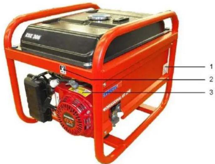
text_image
1 2 3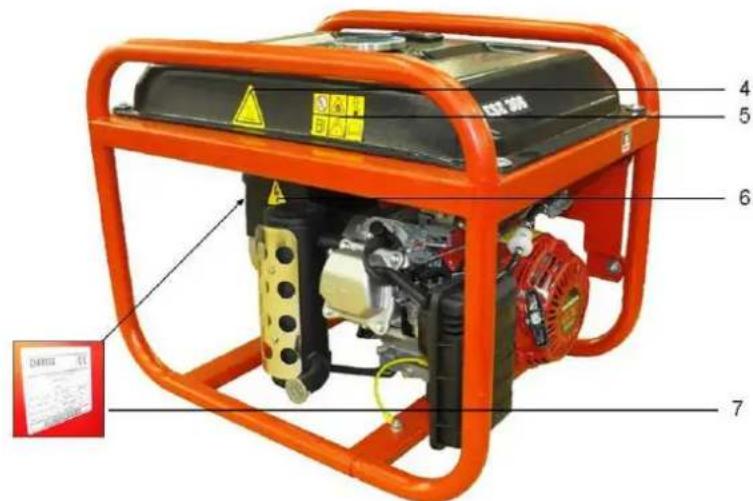
text_image
Labeled diagram of a portable power supply unit with numbered parts and warning labelsFig. 2.1: Labels on the generator
1 Note on sound power level 5 General safety instructions
2 Note on refuelling 6 Note on the dangerous electrical voltage
3 General safety instructions (Engine) 7 Generator model plate (on the side of the generator))
4 Note on the hot surface
| Label Designation No. | ||
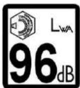 | General warnings | 1 |
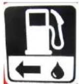 | Note on refuelling | 2 |
 | General warnings about the engine | 3 |
 | NoteHot surfaces | 4 |
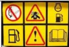 | General safety instructions | 5 |
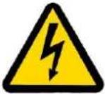 | Note on the dangerous electrical voltage | 6 |
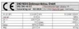 | Model plateSee page 38 for an explanation. | 7 |
Table 2.2: Labels on the generator
2.6 General safety instructions
The operator must know the different parts of the generator and their function and be able to use them.
The operator is responsible for the operating safety of the generator.
The operator is responsible for protecting against unauthorised operation of the generator.
The operator is required to wear his personal safety equipment.
Markings on the generator should always be complete and maintained in a legible condition.
The generator's construction may not be modified in any way.
The engine's nominal rpm has been set in the factory and may not be changed.
The operational reliability and functionality must be checked before and after each use/operation.
The generator may only be operated in the open air.
Do not use any open flame, light or spark-generating devices within the generator's danger zone.
Smoking is absolutely prohibited in the generator's danger zone.
Protect the generator against moisture and precipitation (rain, snow) during operation.
Protect the generator against dirt and foreign matter during operation.
Transport The generator may only be transported after it has cooled down.
The generator may only be transported in a vehicle if it has been adequately secured against tipping over
The generator may only be lifted on the support frame provided for this purpose.
Setting up The generator may only be set up on sufficiently firm ground.
The generator may only be set up on even ground.
The generator must not stand on a wet surface.
Generating electricity The electrical safety must be checked before each start-up.
Do not cover the equipment during use.
Do not obstruct or block the air supply.
Do not use starting aids.
Appliances must not be connected during start-up.
Only tested and authorised cables may be used for the power network.
The entire drawn output must not exceed the maximum nominal output of the generator.
Do not operate the generator without a sound damper.
It is prohibited to operate the generator without air filters and with an opened air filter cover.
Refuelling It is prohibited to refill the fuel tank on the generator during operation.
It is prohibited to refill the fuel tank on the generator when it is still hot.
Use filling aids for refuelling.
Cleaning It is prohibited to clean the generator during operation.
It is prohibited to clean the generator when it is still hot.
Maintenance and repair It is prohibited to service the generator during operation.
work
It is prohibited to service the generator when it is still hot.
The operator may only perform the maintenance and repair work described in this manual.
All other maintenance or repair tasks may only be carried out by specially trained and authorised specialists.
Always remove the spark plug socket before beginning maintenance and/or repair work.
The maintenance intervals specified in the engine manual and in these operating instructions must be observed.
Decommissioning The generator should be put out of service if it is not required for more than 30 days.
Store the generator in a dry, locked room.
Prevent accumulation of resin-type residues in the fuel system by adding a petrol additive.
Note on environmental
The packaging material must be recycled according to the environmental protection regulations applicable at the place of work.
The workplace must be protected against contamination by leaking operating fluids.
Used or remaining operating fluids must be recycled according to the environmental protection regulations applicable at the place of work.
Electrical and electronic appliances, as well as batteries and rechargeable batteries may not be disposed together with domestic waste.
The user is required by law to give back electrical and electronic equipment as well as batteries and accumulators at the end of their service life to public collection facilities set up for this purpose or to the place they were bought from. The symbol on the product, the operating instructions or the packaging refers to this.
Removable batteries and accumulators must be removed from the devices and disposed of separately.
When recycling, recovering materials or achieving other forms of utilising old equipment you are making a major contribution to protecting our environment.
3 Description

The components and functionality of the generator are described in this section.
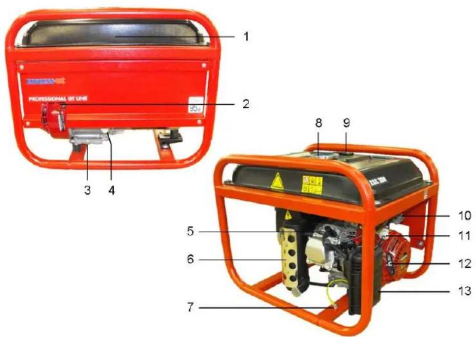
text_image
1 2 3 4 8 9 5 6 7 10 11 12 13 PROFESSIONAL OF LINEFig. 3.1: Generator components
1 Fuel tank 8 Tank cover
2 Motor switch 9 Fuel level indicator
3 Oil drain screw 10 Fuel valve
4 Oil filling screw / oil dipstick 11 Fuel filter
5 Spark plug 12 Reversing starter (starter grip)
6 Exhaust 13 Air filter
7 Screw for potential equalization
3.1 Function and mode of operation
The synchronous generator is coupled rigidly to the drive motor. The aggregate is installed in a stable frame and mounted elastically on the vibration elements in a way which will ensure only low vibrations.
Current collection takes place according to the model over a splash water protected 230 V / 50 Hz safety socket or over 230V / 400V CEE power sockets.
The power generator is designed for mobile use with one or more electrical consumers (protection separation according to VDE 100, Part 551).
4 Commissioning

The operation of the generator is described in this section.
4.1 Transporting the generator
Proceed as follows to transport the generator.
Requirements
These requirements must be fulfilled:
• The generator must be turned off
• The generator must have cooled down
• The fuel cock is in the position "Closed"

CAUTION!
A sliding away or falling device can crush the hand and feet.
- Note the weight of the machine varying between 41 to 86 kg (depending on the model).
- The device must be carried by 2 (ESE 206 / 306 HS-GT) or 4 persons (ESE 406 / 606 (D) HS-GT (ES))
- Walk slowly.
- Do not place your feet under the device
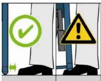
text_image
Safety warning sign showing checkmark and warning triangle with arrows indicating delayCarrying the generator
- Grip the device on the support frame.
- Lift the gene rator.
- Carry generator to place of work.
- Set down the generator.
- Let go of the support frame.
√ The generator has been carried to its place of work.
4.2 Setting up the generator
Proceed as follows to set up the generator.
Requirements
These requirements must be fulfilled:
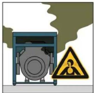
• An even and firm substratum outdoors
• There are no inflammable materials at the place of work
• There are no explosive materials at the place of work
- The device must be installed freely (it must not be covered)

CAUTION!
Leaking engine oil and petrol can contaminate the soil and groundwater.
- Prevent leaking of engine oil and petrol.
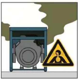
natural_image
Illustration of a mechanical device with a warning sign and smoke, no text or symbols present.
natural_image
Diagram of a mechanical device with green support frames and a central circular component (no text or symbols)Setting up the generator
The generator is set up as follows:
- Prepare the work site.
- Transport the generator to the work site.
- Secure the generator against tipping over / slipping if necessary.
√ The device is in position.
4.3 Refuelling the generator
Proceed as follows to refuel the generator.
Requirements
These requirements must be fulfilled:
• The device must be shut off.
• The device must be cooled down.
- Sufficient ventilation must be available.
CAUTION!
Escaping petrol can burn or explode.
- Avoid petrol escaping.
- Generator is switched off.
- Generator has cooled down.
- Avoid open flames and sparks.
CAUTION!
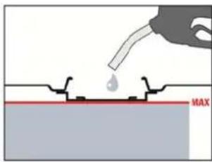
Escaping petrol can contaminate the soil and groundwater.
- Do not fill the tank completely.
- Use filling aid.

CAUTION!
The wrong fuel destroys the engine.
- Only refuel with lead-free regular grade petrol ROZ 91.

CAUTION!
Operation with E10 is possible.
• Only use E10 with ROZ 95.
- Fuel which has been in storage for a period of more than 4 weeks should not be used.
- Empty the fuel tank and the carburettor if the device is to be left unused for a longer period of time.
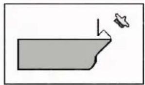
• Wipe off sprayed on fuel carefully.
text_image
MAX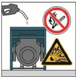
text_image
Safety warning illustration showing fuel pump, no smoking symbol, and hazard warning signRefuelling the device Refuel the generator as follows:
- Turn the fuel cock to "OFF".
- Unscrew tank cover.
- Lead the filling aid into the tank.
- Fill in petrol.
- Remove the filling aid.
- Screw on tank cover
√ The device is refuelled.
4.4 Fill the generator with engine oil

CAUTION!
The generator is always delivered without any engine oil in it.
- it is not possible to start the generator if the oil level is too low since the engines are fitted with oil level monitoring.
Requirements These requirements must be fulfilled:
• The device must be shut off.
• The device must be cooled down.

CAUTION!
Leaking engine oil can contaminate the soil and groundwater.
- Do not fill up the crankcase to the maximum (check the fill level at the oil dipstick).
- Use a filling aid.

CAUTION!
Using the wrong engine oil will destroy the engine. Please check the average ambient temperature and fill with the types of oil specified in the following:
• .... < 0° => SAE 10 or 10 W30; 10W40
- 0^ - 25^ SAE 20 or 10W30; 10W40
- 25^ - 35^ SAE 30 or 10W30; 10W40
- 35^ > => SAE 40 or 10W30; 10W40
• Never mix a commercial additive with the oil.
Fill the device with engine oil
Fill the generator with engine oil as follows:
- Remove the oil dipstick.
- Introduce the filling aid into the filling opening. (for example a filling funnel not in the scope of delivery)
- Pour in the engine oil up to the edge of the oil filler neck. (see page 38 "Technical Data") for the quantity of oil to use).
- Remove the filling aid.
- Screw in the oil dipstick.
- Repeat the filling process if the oil level is too low.
- Screw in the oil dipstick again
√ The device is now filled with engine oil.
natural_image
Simple line drawing of a boat hull with a small boat and arrow indicating direction (no text or symbols)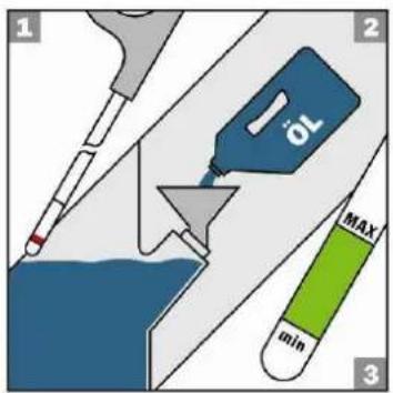
text_image
1 2 JOL MAX min 34.5 Starting the generator
Proceed as follows to start the generator.
Requirements
These requirements must be fulfilled:
• checked and tested for electrical safety
- a full fuel tank
- an adequate oil level
• sufficient air supply/ventilation
• appliances switched off or disconnected
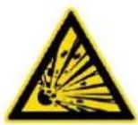
CAUTION!
Operating fluids can burn or explode.
• Prevent leaking of engine oil and petrol.
- Do not use starting aids.
- Avoid open flames and sparks.
Establishing the fuel supply
The fuel supply takes place over an own tank on the generator.
text_image
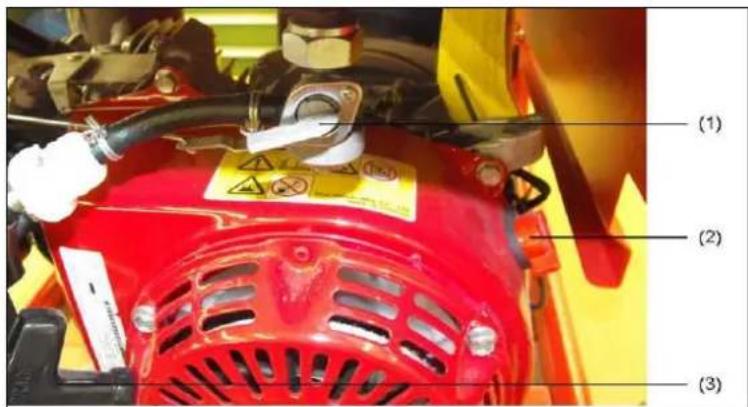
(1) (2) (3)Fig. 4.1: Open / close the fuel cock
| Switch position | Operation Position | |
| OFF | closed | horizontal |
| ON | open | vertical |
Table 4.1: Switch positions for the fuel cock.
Establish a connection to the fuel supply system as follows:
- Set the fuel cock to the "ON" position.
√ The fuel supply is established.

CAUTION!
Exhaust gases can cause fatal asphyxiation.
- Provide for sufficient ventilation.
- Only operate the generator outdoors.
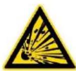
CAUTION!
Hot parts can ignite flammable and explosive materials.
- Avoid flammable materials at the work location.
- Avoid explosive materials at the work location.

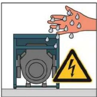
CAUTION!
Heat or moisture destroys the device.
- Avoid overheating (sufficient ventilation).
- Avoid moisture.
natural_image
Illustration of a hand reaching into a water drop onto an industrial machine with a warning symbol (no text or labels)HAND START Start the engine as follows:
- Push the choke into the Start position "see inscription on the air filter" (only for a cold engine).
- Set engine switch to the "ON" position.
- Slowly pull the cord grip to the pressure point, and then give it a rapid even pull.
√ The engine starts.
Support yourself with a hand on the grip on the device to make pulling easier.
- Set the choke in its basic position.
√ The engine has started.
ELECTRICAL START
- Push the choke into the Start position "see inscription on the air filter" (only for a cold engine).
- Turn the key-operated switch all the way to the right into the START position until the engine starts and then release.
√ The engine starts.
3. Set the choke in its basic position.
√ The engine has started.
NOTE Only activate the starter briefly (max. 5 - 10 seconds). Never start or run the engine with the battery disconnected.
NOTE The electrical consumers can be connected or switched in after a warming-up phase of about one minute.
4.6 Connecting appliances
Proceed as follows to connect appliances to the generator.
Requirements
These requirements must be fulfilled:
- generator started
• a completed warming-up phase
• appliance switched off
CAUTION!
Electric shocks cause injury or death.
- The generator may neither be connected to other energy distribution systems (e.g. public power supply) nor to other energy generation systems (e.g. other generators).
Connecting appliances
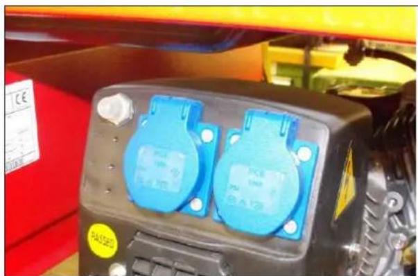
You can connect the appliance with a protective contact plug 230 V alternating current (or 400 V three-phase alternating current, only ESE 506 / 606 DHS-GT).
natural_image
Close-up of a mechanical device with two blue electrical connectors and a yellow label (no readable text or symbols)Fig. 4.2: Connecting appliances
4.7 Switching the generator off
Proceed as follows to shut down the generator.
CAUTION!
Hot parts can ignite flammable and explosive materials.
- Avoid flammable materials at the work location.
- Avoid explosive materials at the work location.
- Allow generator to cool down.
The generator is switched off as follows:
- Switch off or disconnect consumers.
- Continue to run the engine for about two minutes.
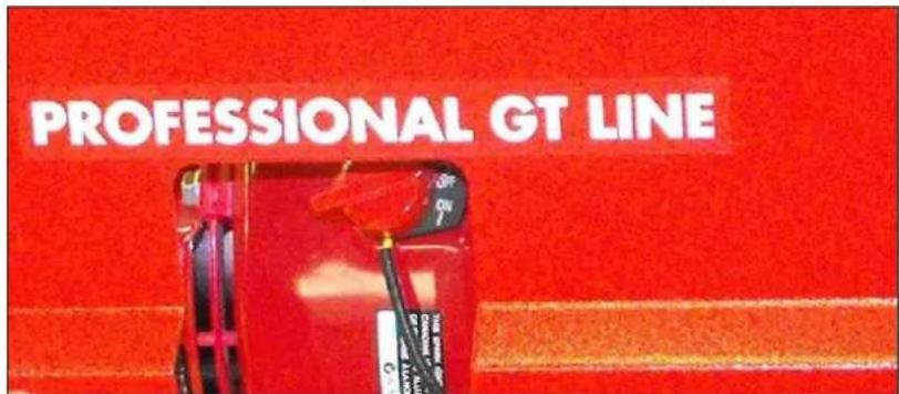
text_image
PROFESSIONAL GT LINEFig. 4.3: Turning the motor off.
- Set engine switch to the "OFF" position.
√ The engine is off. - Set the fuel cock to "OFF".
- Allow the generator to cool down.
√ The generator is switched off.
4.8 Putting the generator out of service
Used only rarely
If the generator is only used very rarely then there may be difficulties in getting it started.
The generator should therefore be run for about 30 minutes a week to avoid these problems.
Storage
If you do not need the generator for a longer period of time then it should be decommissioned and put into storage.

CAUTION!
Escaping engine oil and fuel can pollute the earth and the ground water.
Proceed as follows to decommission the generator.
Requirements
These requirements must be fulfilled:
• Appliances switched off or disconne cted
• The device must be shut off.
• The device is still somewhat warm
Draining off the engine oil
Drain off the engine oil in the generator as follows:
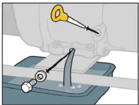
natural_image
Mechanical assembly diagram showing a tool interacting with a bolt and nut (no text or symbols)Fig. 4.4: Remove the oil drain screw
- Place an oil collecting pan under the oil drain screw.
Note
The capacity of the oil collecting pan differs according to the model (0.6 to 1.1 litres). Exact details can be found on page 38 in the table "Engine oil quantities".
Environmental protection
- Release the oil drain screw using an open-ended spanner and remove.
- Drain off the engine oil.
Used or remaining operating fluids must be recycled according to the environmental protection regulations applicable at the place of work.
- Screw the oil drain screw back in again and tighten down using the open-ended spanner.
√ The motor oil has been drained.
Emptying the petrol tank
Empty the petrol tank on the generator as follows:
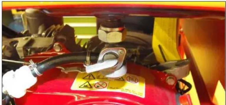
text_image
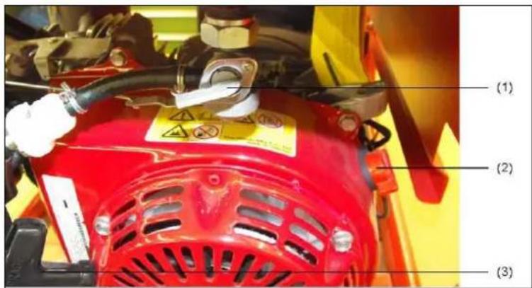
Close-up of a red vehicle engine component with warning signs and safety symbols visible on the panel.Fig. 4.5: Close the fuel valve
CAUTION!
Escaping petrol can burn or explode.
- Avoid allowing petrol to escape.
- Generator is switched off.
- Generator has cooled down.
- Avoid open flames and sparks.
NOTE
- Place the collecting container next to the generator.
The capacity of the collecting container varies. Exact details can be found on page 38 in the table "Contents of the tank".
- Turn the fuel cock to "OFF".
- Carefully detach the fuel hose from the carburetto r and put into the collecting container.
- Turn the fuel cock to "ON".
√ The fuel is drained off.
Environmental protection
Used or remaining operating fluids must be recycled according to the environmental protection regulations applicable at the place of work.
- Turn the fuel cock to "OFF".
- Carefully attach the fuel hose to the carburettor again.
√ The petrol is drained off.
Preserving the engine compartment
Preserve the engine compartment on the generator as follows:
Requirements
These requirements must be fulfilled:
- a switched off device
• no further fuel in the tank - fuel cock at "OFF"
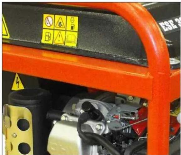
text_image
Close-up of an orange industrial machine component with warning symbols and safety labelsFig. 4.6: Detach the spark plug socket
- Detach the spark plug socket
- Unscrew the spark plug using the spark plug spanner.
- Put 1 ml of oil in the opening for the spark plug.
- Screw in the spark plug again and tighten down.
- Slowly pull on the cable pull for starting the engine a number of times so that the oil is distributed throughout the engine compartment.
- Put the spark plug socket in place again
√ The engine compartment is now preserved.
Cleaning the air filter Clean the air filter on the generator as follows:
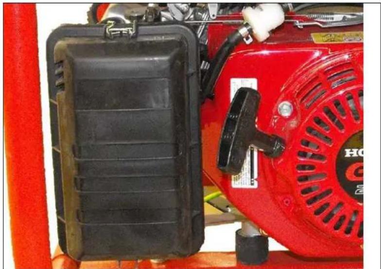
natural_image
Close-up of a red tractor with visible exhaust pipe and control panel (no text or symbols)Fig. 4.7: Remove the air filter
- Remove the air filter cover from the air filter housing.
- Clean the air filter insert in a suitable container in warm water with a detergent or with non-flammable washing petrol.
- Pour engine oil onto the filter and push out excess oil.
- Insert the air filter.
- Again attach the air filter cover to the air filter housing
√ The air filter is cleaned and mounted.
Environmental protection
Used or residual operating fluids and cleaning agents should be recycled according to the regulations valid at the place of use for environmental protection.
5 Maintaining the generator

Only personnel from the manufacturer may carry out maintenance or repair work not described in this section.
5.1 Maintenance plan
The maintenance work should be performed according to the time intervals quoted in the Honda engine operating instructions. The screw connections should also be checked before every operation and the device cleaned if necessary.
Maintenance work may only be performed by suitable persons.
Perform all maintenance work in the maintenance plan according to details given in the operating and maintenance manual for the engine.
We recommend that this work be performed by an authorised ENDRESS service station.
^1 only a paper insert
^2 have performed by an ENDRESS franchised dealer
| Maintenance work Time interval in months or operating hours | |||||
| for each use | in the first month or 20h | every 3 months or 50h | every 6 months or 100h | every year or every 300h | |
| Check the oil level | X | ||||
| Change the oil | X | ||||
| Check the air filter | X | ||||
| Clean air filter | X | ||||
| Replace the air filter | (X) ^1 | ||||
| Check / adjust spark plugs | X | ||||
| Exchange spark plugs | X | ||||
| Clean the deposits beaker | X | ||||
| Clean the combustion chamber | every 500h ^(2) | ||||
| Check / adjust spark plugs | X ^(2) | ||||
| Check / adjust valve play | X ^(2) | ||||
| Replace fuel tank and filter | X | ||||
| Clean area around mufflers, linkages, and springs | X | ||||
| Check fit of screws, nuts, and bolts | X | ||||
| Electrical safety | X | ||||
| Check condition and tightness of the fuel hoses and connections. | Every 2 years ^(2) (replace if necessary) | ||||
5.2 Checking the electrical safety
Only appropriately authorised personnel may check the electrical safety.
The electrical safety must be checked every time before operating the generator in accordance with the applicable VDE regulations, EN and DIN standards and especially the current version of the BGV A3 accident prevention regulations.
6 Troubleshooting

This section contains faults and problems which can be removed by suitable persons during operation.
Each occurring problem is described with its possible cause and the respective corrective measure.
The authorised personnel must immediately shut down the generator and inform the responsible and authorised service personnel if a problem cannot be solved with the aid of the following table.
*A service station is recommended for performing these checks or repairs
| Malfunction Possible cause Correction | ||
| No current available from the sockets | The machine speed is too low | *Adjust the machine speed |
| Disconnected or short-circuited cabling | Check the consumers | |
| Rotor or stator winding - open circuit/short-circuited | *Test the winding resistance; replace the winding if necessary | |
| A low output voltage for a zero load | The machine speed is too low. | *Adjust the machine speed |
| Rotor or stator winding open circuit/short-circuited | *Test the winding resistance; replace the winding if necessary | |
| A high output voltage for a zero load | The machine speed is too high | *Adjust the machine speed |
| A low output voltage under loadAn uneven output voltage | The machine speed for full load is too low | *Adjust the machine speed |
| Too much load present Reducing the existing load | ||
| An uneven load present Remove the whole load then apply again individually in order to establish which one creates the uneven function. | ||
| Noisy operation Loose generator | or machine screws | Tighten all assembly parts |
| Short-circuit in the generator field/load | *Check the winding resistance, replace the field winding and check the loading devices for a short-circuit if necessary. Replace the defective loading device. | |
| Malfunction Possible cause Correction | |||
| A faulty bearing *Replace the bearing. | |||
| The machine does not start No fuel Check the fuel | |||
| Fuel cock in the position "OFF" | Bring the fuel cock into the open position "ON" | ||
| Rocker switch in the "OFF" position | Bring the rocker switch into the "ON" position | ||
| Spark plug socket dirty or loose | Clean the spark plug socket. Set the opening if necessary | ||
| Spark plug dirty Clean the spark plug; replace if necessary | |||
Table 6.1: Problems during generator operation
*A service station is recommended for performing these checks or repairs
7 Technical specifications

The technical specifications concerning use of the generator are described in this section.
Technical specifications
| Designation | |||
| Model ESE 206 HS-GT ESE 306 HS-GT ESE 406 HS-GT ES | |||
| Generator | synchronous | synchronous | synchronous |
| Frequency / Protection Class | 50 Hz / IP 23 50 Hz / IP 23 50 Hz / IP 23 | ||
| Rated voltage 230 V 1~ 230 V 1~ | |||
| Max. power output (LTP) VA | 2900 | 3400 | 5100 |
| Continuous power (COP) in watts | 2200 | 2600 | 3900 |
| Nominal output factor cos/ (phi) | 0.9 | 0.9 | 0.9 |
| Engine type | Honda GX1601-cylinder 4-strokeOHC, air-cooled | Honda GX2001-cylinder 4-strokeOHC, air-cooled | Honda GX2701-cylinder 4-stroke OHC, air-cooled |
| Cubic capacity in cm3 163 | 196 | 270 | |
| Output (3000 rpm) in kW | 2.5 | 3.3 | 4.6 |
| Tank capacity (litres) | 20 | 20 30 | |
| Sound power level at workplace LpA * | 88dB(A) | 89dB(A) | 89dB(A) |
| Sound power level at a distance of 7m LpA ** | 71dB(A) | 71dB(A) | 72dB(A) |
| Sound power level ** LWA | 96dB(A) | 96dB(A) 97dB(A) | |
| Length in mm | 637 | 637 | 800 |
| Width in mm | 473 | 473 | 538 |
| Height in mm | 500 | 500 | 576 |
| Weight kg 41 | 43 61 / 66 (E-Start) | ||
| Engine oil quantity | 0.6 litres | 0.6 litres | 1.1 litres |
Table 7.1: Technical Specifications for the Generator T1
| Designation | |||||
| Model ESE 506 DHS-GT ESE 606 HS-GT ES ESE 606 DHS-GT ES | |||||
| Generator | synchronous | synchronous | synchronous | ||
| Frequency / Protection Class | 50 Hz / IP 23 50 Hz / | IP 23 50 Hz / IP 23 | |||
| Rated voltage 230 V 1~400 V 3~230 | V 1~230 V 1~400 V 3~ | ||||
| Max. power output (LTP) VA | 4200 | 6300 | 7200 | 5500 | 8300 |
| Continuous power (COP) in watts | 2800 | 4300 | 5500 | 3700 | 5600 |
| Nominal output factor cos/ (phi) | 0.9 | 0.8 | 0.9 | 0.9 | 0.8 |
| Engine type | Honda GX2701-cylinder 4-stroke OHC, air-cooled | Honda GX3901-cylinder 4-stroke OHC, air-cooled | Honda GX3901-cylinder 4-stroke OHC, air-cooled | ||
| Cubic capacity in cm^3 | 270 | 389 | 389 | ||
| Output (3000 rpm) in kW | 4.6 | 6.0 | 6.0 | ||
| Tank capacity (litres) | 30 | 30 | 30 | ||
| Sound power level at workplace L_pA * | 89dB(A) | 89dB(A) | 89dB(A) | ||
| Sound power level at a distance of 7m L_pA ** | 72dB(A) | 72dB(A) | 72dB(A) | ||
| Sound power level ** L_WA | 97dB(A) | 97dB(A) | 97dB(A) | ||
| Length in mm | 800 | 800 | 800 | ||
| Width in mm | 538 | 538 | 538 | ||
| Height in mm | 576 | 576 | 576 | ||
| Weight kg | 69 | 73 / 78 (E-Start) | 81 / 86 (E-Start) | ||
| Engine oil quantity | 1.1 litres | 1.1 litres | 1.1 litres | ||
Table 7.2: Technical Specifications for the Generator T2
* measured at a distance of 1 m and a height of 1.6 m in accordance with ISO 3744 (Part 10)
** measured in accordance with ISO 3744 (Part 10)
Ambient conditions
| Designation Value Unit | ||
| Setting up height above sea level | < 100 [m] | |
| Temperature | < | |
| Relative air humidity < 30 [%] | ||
Table 7.3: Ambient conditions for the generator
Reduced output
| Output reduction for each additional | Unit |
| 1% | 100 |
| 4% | 10 |
Table 7.4: Generator performance reduction dependent on the ambient conditions
Distribution network
| Line max. line | length | Unit |
| HO 7 RN-F (NSH öu) 1.5 mm ^2 | 60 | [m] |
| HO 7 RN-F (NSH öu) 2.5 mm ^2 | 100 | [m] |
Table 7.5: Maximum line length of the distribution network as a function of the cable cross-section
Explanation of the type plate
| CE | ENDRESS Elektrogerätebau GmbH | |||
| ESE 206 HS-GT | Neckartenzlinger Straße 39D-72658 Bempflingen, Germany | |||
| Generating set ISO 8528 | ||||
| Pr (COP) | 2.2 kW | S/N | 112300/ 00001 | |
| cos φr | 0.9 | fr | 50Hz | |
| Ur 1~ | 230 V | lr | 10.9A | |
| IP | 23 | hmax | 1000m | |
| Tmax | 40°C | Class | G1 | |
| Mfg | 2011 | m | 41 kg | |
| Nominal output in kW | Series number |
| Nominal output factor | Nominal frequency in Hertz |
| Nominal voltage in volts | Nominal current in amperes |
| International protection class | Maximum installation height in metres |
| Maximum ambient temperature | Design class |
| Year of construction | Mass in kilograms |
8 Warranty
For industrial use the warranty period is 6 months from the date of purchase.
Please contact the dealer you bought the product from in the case of making a claim under warranty or if there is any need for replacement parts.
Please ensure that you always accompany your defective device with the following documents:
• The purchase document (receipt or invoice)
• A description of the fault which has occurred
Service – Hotline
Tel:+49(0)7123-9737-44
E-mail: service@endress-generators.de
declare under our sole responsibility that the product to which this declaration relates is in conformity with the following relevant regulations
and subsequent modification and integrations
measuring procedure according to ISO 3744 (part110)
conformity assessment procedure according to 2000/14/EC procedure VIII. (notified body)
de d'evaluation de conformite 2000/14/EC procedure VIII. (organisme avise
Directorate General Environment
Unit C.1 Air, Noise & Transport
BU-9 06/204 - B-1049 Brussels Belgium
verantwortlich
authorized by
le responsable
el responsable
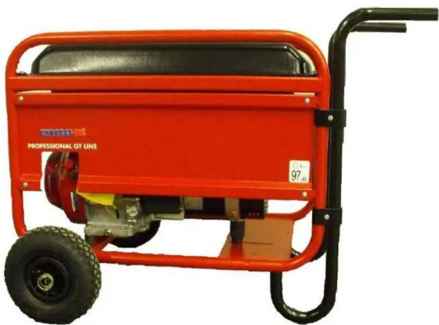
A wheel set can be optionally obtained
natural_image
Red professional OT line portable electric transporter with black frame and wheels (no visible text or symbols)Make things simper by having the wheel set which is suitable for your generator:
can be obtained as an accessory for the following models:
ESE 406 / 506 / 606 (D)HS-GT (ES) Order No. 161 026
Notes
ENDRESS
natural_image
Red professional GT line equipment with visible internal components and branding (no readable text beyond branding)ESE 206 HS-GT
Article n° 112300
ESE 406 HS-GT
Article n° 112302
ESE 506 DHS-GT
Article n° 112304
ESE 606 HS-GT ES
Article n° 112307
ESE 606 DHS-GT ES
Article n° 112308
ESE 306 HS-GT
Article n° 112301
ESE 406 HS-GT ES
Article n° 112306
ESE 606 HS-GT
Article n° 112303
ESE 606 DHS-GT
Article n° 112305
text_image
Labeled diagram of an industrial power plant with numbered components and warning labelstext_image
Safety warning sign with checkmark and warning triangle, indicating correct and incorrect statusTransport du groupe
natural_image
Illustration of a mechanical device with a warning sign and smoke, no text or symbols present.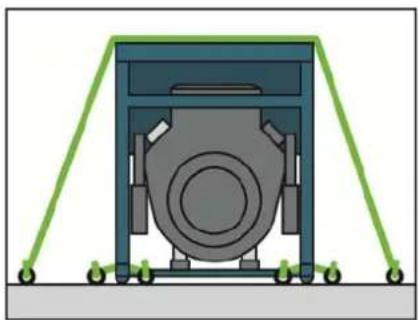
natural_image
Diagram of a mechanical device with green support frames and a central circular component (no text or symbols)text_image
Safety warning illustration showing a pump nozzle, no smoking, and hazard symbol with text labelsnatural_image
Simple line drawing of a boat hull with an arrow indicating direction (no text or symbols)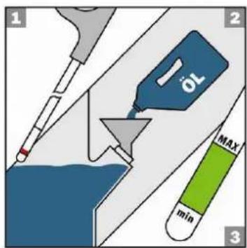
text_image
1 2 10 MAX min 3natural_image
Illustration of a hand reaching into a water drop onto a mechanical device with a warning symbol (no text or labels)natural_image
Close-up of a mechanical device with two blue electrical connectors and labeled buttons (no readable text or symbols)natural_image
Mechanical assembly diagram showing a tool interacting with a bolt and nut (no text or symbols)text_image
Close-up of a red vehicle battery pack with warning signs and safety symbols visibletext_image
Close-up of an orange industrial machine component with warning labels and safety symbolsnatural_image
Close-up of a red tractor with visible exhaust pipe and control panel (no text or symbols)and subsequent modification and integrations
measuring procedure according to ISO 3744 (part10)
conformity assessment procedure according to 2000/14/EC procedure VIII. (notified body)
procede d'evaluation de conformite 2000/14/EC procedure VIII. (organisme avise.)
Directorate General Environment
Unit C.1 "Air, Noise & Transport"
BU-9 06/204 - B-1049 bruxelles
Belgium
verantwortlich
authorized by
le responsable
el responsable
natural_image
Red industrial portable electricity generator with black frame and wheels (no visible text or symbols)natural_image
Red professional gas turbine machine with visible internal components and branding (no text or symbols on the device body)ESE 206 HS-GT
Artikelnr. 112300
ESE 406 HS-GT
Artikelnr. 112302
ESE 506 HS-GT
Artikelnr. 112304
ESE 606 RS-GT ES
Artikelnr. 112307
ESE 606 RS-GT ES
Artikelnr. 112308
ESE 306 HS-GT
Artikelnr. 112301
ESE 406 RS-GT ES
Artikelnr. 112306
ESE 606 HS-GT
Artikelnr. 112303
ESE 606 HS-GT
Artikelnr. 112305
text_image
Labeled diagram of an orange portable power supply unit with warning labels and component annotationstext_image
Safety warning symbols including checkmark, warning triangle, and exclamation mark on a windowDe generator dragen
natural_image
Illustration of a mechanical device with a warning sign and smoke, no text or symbols present.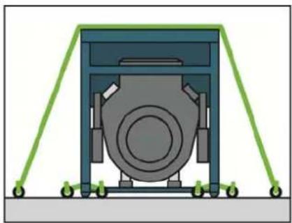
natural_image
Diagram of a mechanical device with green support frames and a central circular component (no text or symbols)text_image
Safety warning illustration showing fuel pump, no smoking, and hazard symbol with Chinese textnatural_image
Simple line drawing of a boat hull with a small boat and a small airplane (no text or symbols)
text_image
1 2 1 OL MAX min 34.5 De generator starten
natural_image
Illustration of a hand reaching into a rain drop onto a mechanical device with a warning symbol (no text or labels)√ De motor is gestart.
ELEKTRISCHE START
natural_image
Close-up of a mechanical device with two blue electrical connectors and a yellow label (no readable text or symbols)natural_image
Mechanical assembly diagram showing a tool interacting with a bolt and nut (no text or symbols)Afb. 4.4: Neem de olieaftapplug los
text_image
Close-up of a red vehicle battery pack with warning signs and safety symbols visible√ De benzine is afgetapt.
text_image
Close-up of an orange industrial machine component with warning symbols and labels including 'No Concern' and safety icons.Afb. 4.6: Maak de bougiedop los
natural_image
Close-up of a red tractor with visible exhaust pipe and control panel (no text or symbols)and subsequent modification and integrations
et aux modifications successives at integrations
measuring procedure according to ISO 3744 (part110)
conformity assessment procedure according to 2000/14/EC procedure VIII. (notified body
procede d'evaluation de conformite 2000/14/EC procedure VIII. (organisme avise:)
Directorate General Environment Unit C 14 Air, Vair & Transport
Unit C.1 - Alt, Some & Transport BU-0.06/204 - B-1049 Bruxelles
Belgium
verantwortlich
authorized by
le responsable
el responsable
natural_image
Red and black industrial machine with visible wheels and a labeled number 97-08 (no text or symbols on the device itself)natural_image
Red professional GT line equipment with visible internal components and branding (no text-heavy elements)ESE 206 HS-GT
Artikelnr. 112300
ESE 406 HS-GT
Artikelnr. 112302
ESE 506 DHS-GT
Artikelnr. 112304
ESE 606 HS-GT ES
Artikelnr. 112307
ESE 606 DHS-GT ES
Artikelnr. 112308
ESE 306 HS-GT
Artikelnr. 112301
ESE 406 HS-GT ES
Artikelnr. 112306
ESE 606 HS-GT
Artikelnr. 112303
ESE 606 DHS-GT
Artikelnr. 112305
text_image
Labeled diagram of an industrial power plant with numbered components and warning labelstext_image
Safety warning symbols including checkmark, warning triangle, and exclamation mark on a documentBära generatorn
natural_image
Illustration of a mechanical device with a warning sign and smoke, no text or symbols present.
natural_image
Diagram of a mechanical device with green support frames and a central circular component (no text or symbols)text_image
Safety warning illustration showing fuel pump, no smoking, and hazard symbol with Chinese textnatural_image
Simple line drawing of a boat hull with an arrow indicating direction (no text or symbols)
text_image
1 2 1 OL MAX min 34.5 Starta generatorn
natural_image
Illustration of a hand reaching into a water drop onto an industrial machine with a warning symbol (no text or labels)natural_image
Close-up of a mechanical device with two blue electrical connectors and a red vehicle in the background (no visible text or symbols)Fig. 4.2: Ansluta apparater
natural_image
Mechanical assembly diagram showing a tool interacting with a bolt and nut (no text or symbols)text_image
Close-up of a red vehicle battery pack with warning signs and safety symbols visibletext_image
Close-up of an orange industrial machine component with warning labels and safety symbolsFig. 4.6: Lossa tändstiftets kontakt
natural_image
Close-up of a red tractor with visible exhaust pipe and control panel (no text or symbols)Tabell 6.1: Problem under generators drift
Tel: +49(0)7123-9737-44
E-post: service@endress-generators.de
and subsequent modification and integrations
measuring procedure according to ISO 3744 (part110)
conformity assessment procedure according to 2000/14/EC procedure VIII. (notified body)
procede d'evaluation de conformite 2000/14/EC procedure VIII. (organisme avise:)
Directorate General Environment
Unit C.1 "Air, Noise & Transport"
BU-9 06/204 - B-1049 kinetics
Belgium
verantwortlich
authorized by
le responsable
el responsable
natural_image
Red professional electric generator with black handle and wheels (no visible text or symbols)natural_image
Red professional GT line equipment with visible internal components and branding (no text-heavy elements)ESE 206 RS-GT
Emne nr. 112300
ESE 406 HS-GT
Emne nr. 112302
ESE 506 DHS-GT
Emne nr. 112304
ESE 606 HS-GT ES
Emne nr. 112307
ESE 606 DHS-GT ES
Emne nr. 112308
ESE 306 HS-GT
Emne nr. 112301
ESE 406 HS-GT ES
Emne nr. 112306
ESE 606 HS-GT
Emne nr. 112303
ESE 606 DHS-GT
Emne nr. 112305
1 General information....5
text_image
Labeled diagram of an orange portable power supply unit with numbered parts and warning labelstext_image
Safety warning sign showing green checkmark and yellow warning triangle with exclamation markBære generatoren
natural_image
Illustration of a mechanical device with a warning sign indicating hazard (no text or symbols present)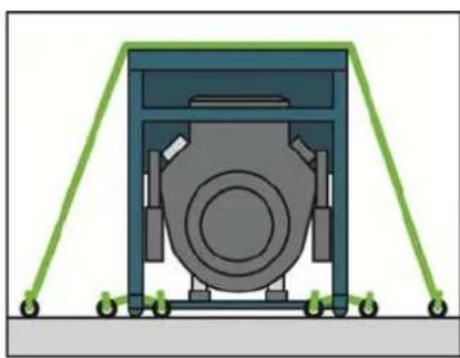
natural_image
Diagram of a mechanical device with green support frames and a central circular component (no text or symbols)text_image
Safety warning illustration showing a fuel pump, no smoking, and hazard symbol with Chinese textnatural_image
Simple line drawing of a gray irregular shape with a small star-like symbol above it (no text or labels)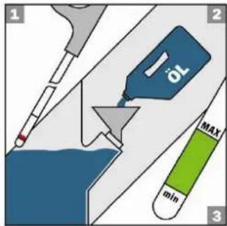
text_image
1 2 1 OL MAX min 34.5 Start af generatoren
natural_image
Illustration of a hand reaching toward a mechanical device with water droplets, next to a warning sign (no text or symbols on the diagram itself)natural_image
Close-up of a mechanical device with two blue electrical connectors and a red vehicle in the background (no visible text or symbols)natural_image
Mechanical assembly diagram showing a tool interacting with a bolt and nut (no text or symbols)Fig. 4.4: Fjern olieaftapningsskruen
text_image
Close-up of a red vehicle battery pack with warning signs and safety symbols visibletext_image
Close-up of an orange industrial machine component with warning labels and safety symbolsnatural_image
Close-up of a red tractor with visible exhaust pipe and control panel (no text or symbols)and subsequent modification and integrations
measuring procedure according to ISO 3744 (part110)
conformity assessment procedure according to 2000/14/EC procedure VIII. (notified body)
procede d'evaluation de conformite 2000/14/EC procedure VIII. (organisme avise:)
Directorate General Environment Unit C 1 "Air Noise & Transport"
BUI-9 06/204 - B-1049 Bruxelles
Belgium
verantwortlich
authorized by
le responsable
el responsable
natural_image
Red and black industrial machine with visible wheels and a labeled number 97-08 (no readable text beyond branding)natural_image
Red professional GT line equipment with visible internal components and branding (no text-heavy elements)ESE 206 HS-GT
Tuotenro 112300
ESE 406 HS-GT
Tuotenro 112302
ESE 506 DHS-GT
Tuotenro 112304
ESE 606 HS-GT ES
Tuotenro 112307
ESE 606 DHS-GT ES
Tuotenro 112308
ESE 306 HS-GT
Tuotenro 112301
ESE 406 HS-GT ES
Tuotenro 112306
ESE 606 HS-GT
Tuotenro 112303
ESE 606 DHS-GT
Tuotenro 112305
text_image
Labeled diagram of an industrial power plant with numbered components and warning labelstext_image
Safety warning signs showing checkmark and warning triangle with arrows indicating left-hand rulenatural_image
Illustration of a mechanical device with a warning sign and smoke, no text or symbols present.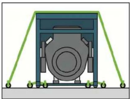
natural_image
Diagram of a mechanical device with green support frames and a central circular component (no text or symbols)text_image
Safety warning illustration showing fuel pump, no smoking, and hazard symbol with Chinese textnatural_image
Simple line drawing of a boat hull with a small star symbol above it (no text or labels)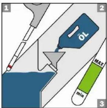
text_image
1 2 1 MAX min 3natural_image
Illustration of a hand reaching into a water drop onto an industrial machine with a warning symbol (no text or labels)MANUAALINEN KÄYNNISTYS
natural_image
Close-up of a mechanical device with two blue electrical connectors and a red panel, no visible text or symbols.natural_image
Mechanical assembly diagram showing a tool interacting with a bolt and nut (no text or symbols)text_image
Close-up of a red vehicle battery pack with warning signs and safety symbols visibletext_image
Close-up of an orange industrial machine component with warning labels and safety symbolsnatural_image
Close-up of a red tractor with visible exhaust pipe and control panel (no text or symbols)and subsequent modification and integrations
| European Commission |
| Directorate General Environment |
| Unit C.1 "Air, Noise & Transport" |
| BU-9 06/204 - B-1049 Bruxelles |
| Belgium |
verantwortlich authorized by le responsable el responsable
natural_image
Red professional electric generator with black handle and wheels (no visible text or symbols)natural_image
Red professional GT line equipment with visible internal components and branding (no text-heavy elements)ESE 206 HS-GT
Artikkel nr. 112300
ESE 406 HS-GT
Artikkel nr. 112302
ESE 506 DHS-GT
Artikkel nr. 112304
ESE 606 HS-GT ES
Artikkel nr. 112307
ESE 606 DHS-GT ES
Artikkel nr. 112308
ESE 306 HS-GT
Artikkel nr. 112301
ESE 406 HS-GT ES
Artikkel nr. 112306
ESE 606 HS-GT
Artikkel nr. 112303
ESE 606 DHS-GT
Artikkel nr. 112305
text_image
Labeled diagram of an orange portable power station with warning labels and component annotationsFig. 2.1: Merkelapper på generatoren
text_image
Safety warning signs including checkmark, warning triangle, and exclamation mark on a windowBære generatoren
- Grip apparatet i støtterammen.
- Løfte generatoren.
- Bære generatoren til arbeidsstedet.
- Sette ned generatoren.
- Slipp støtterammen.
√ Generatoren er på plass på arbeidsstedet.
4.2 Sette opp generatoren
natural_image
Illustration of a mechanical device with a warning sign and smoke, no text or symbols present.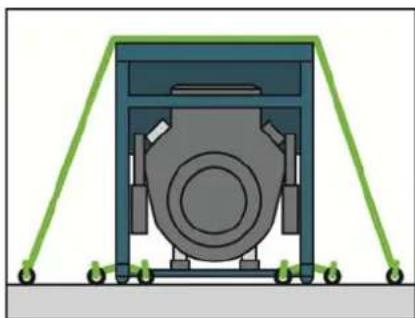
natural_image
Diagram of a mechanical device with green support frames and a central circular component (no text or symbols)text_image
Safety warning illustration showing a fuel pump, no smoking, and hazard symbol with Chinese textnatural_image
Simple line drawing of a boat hull with an arrow indicating direction (no text or symbols)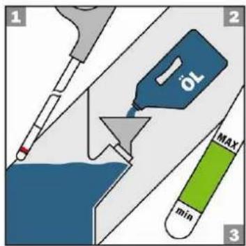
text_image
1 2 3 MAX min4.5 Starte generatoren
natural_image
Illustration of a hand reaching into a water drop onto an industrial machine with a warning symbol (no text or labels)natural_image
Close-up of a mechanical device with two blue electrical connectors and a yellow label (no readable text or symbols)Fig. 4.2: Koble til redskaper
natural_image
Mechanical assembly diagram showing a tool interacting with a bolt and nut (no text or symbols)natural_image
Close-up of a red vehicle engine compartment with visible warning signs and electrical components (no readable text or symbols)Fig. 4.5: Lukk drivstoffventilen
FORSIKTIG!
Lekkasjer med drivstoff kan brenne eller eksplodere.
text_image
Close-up of an orange industrial machine's control panel with warning symbols and safety labelsnatural_image
Close-up of a red tractor with visible exhaust pipe and control panel (no text or symbols)Tlf: +49(0)7123-9737-44
E-post: service@endress-generators.de
and subsequent modification and integrations
measuring procedure according to ISO 3744 (part10)
conformity assessment procedure according to 2000/14/EC procedure VIII. (notified body)
procede d'evaluation de conformite 2000/14/EC procedure VIII. (organisme avise: )
Directorate General Environment
Unit C.1 "Air, Noise & Transport"
BU-9 06/204 - B-1049 Bruxelles
Belgium
verantwortlich
authorized by
le responsable
el responsable
natural_image
Red professional electric generator with black handle and wheels (no visible text or symbols)natural_image
Red professional GT line equipment with visible internal components and branding (no text-heavy elements)ESE 206 HS-GT
text_image
Labeled diagram of an orange portable power station with warning labels and a small inset image showing a safety report.text_image
Safety warning sign showing green checkmark and yellow warning triangle with exclamation marknatural_image
Illustration of a mechanical device with a warning sign and smoke, no text or symbols present.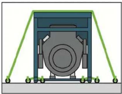
natural_image
Mechanical device with green support frames and a central circular component (no text or symbols visible)text_image
Safety warning illustration showing fuel nozzle, no smoking symbol, and hazard warning signnatural_image
Simple line drawing of a boat hull with a small boat and a small hook, no text or symbols present.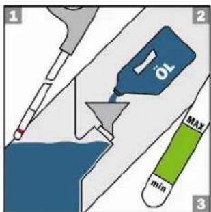
text_image
1 2 3 1 Oil MAX minnatural_image
Illustration of a hand reaching for a water drop from a mechanical device, with a warning symbol (no text or labels)XEIPOKINHTH EKKINHΣH
natural_image
Close-up of a black industrial electrical control panel with two blue buttons, mounted on a red and yellow background (no visible text or symbols)natural_image
Mechanical assembly diagram showing a tool interacting with a component, no text or symbols presenttext_image
Close-up of a red vehicle engine component with warning signs and safety symbols visibletext_image
Close-up of an orange industrial machine with warning labels and safety symbols on the panelnatural_image
Close-up of a red tractor with visible exhaust pipe and control panel (no text or symbols)and subsequent modification and integrations
measuring procedure according to ISO 3744 (part10)
conformity assessment procedure according to 2000/14/EC procedure VIII. (notified body)
procede d'evaluation de conformite 2000/14/EC procedure VIII. (organisme avise:)
Directorate General Environment Unit G U Air Noise & Transport
BU-9 06/204 - B-1049 Bruxelles
Belgium
verantwortlich
authorized by
le responsable
el responsable
natural_image
Red industrial machine labeled 'PROFESSIONAL GT LINE' with visible wheels and a handle (no text beyond branding)natural_image
Red industrial machine labeled 'PROFESSIONAL GT LINE' with visible internal components and wiring (no readable text beyond branding)ESE 206 HS-GT
Поз. № 112300
ESE 406 HS-GT
Поз. № 112302
ESE 506 DHS-GT
Поз. № 112304
ESE 606 HS-GT ES
Поз. № 112307
ESE 606 DHS-GT ES
Поз. № 112308
ESE 306 HS-GT
Поз. № 112301
ESE 406 HS-GT ES
Поз. № 112306
ESE 606 HS-GT
Поз. № 112303
ESE 606 DHS-GT
Поз. № 112305
text_image
Labeled diagram of an orange portable power supply unit with numbered parts and warning symbolstext_image
Safety warning signs showing checkmark and warning triangle with arrows indicating status changenatural_image
Illustration of a mechanical device with a warning sign and a person inside, set against a smoky background (no text or symbols)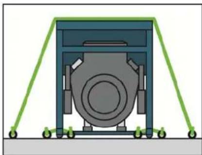
natural_image
Diagram of a mechanical device with green support frames and a central circular component (no text or symbols)text_image
Safety warning illustration showing fuel nozzle, no smoking symbol, and hazard warning symbol with explosion hazardnatural_image
Simple line drawing of a boat hull with an arrow indicating direction (no text or symbols)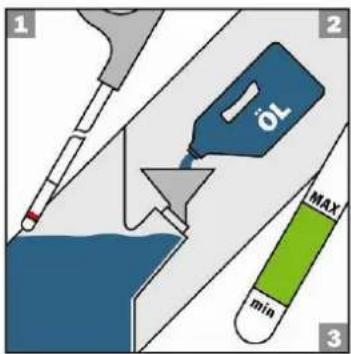
text_image
1 2 1 MAX min 3natural_image
Illustration of a hand reaching into a mechanical device with water droplets, next to a warning sign (no text or symbols on the diagram itself)natural_image
Close-up of a mechanical device with two blue electrical connectors and a yellow label (no readable text or symbols)natural_image
Mechanical assembly diagram showing a tool interacting with a bolt and nut (no text or symbols)text_image
Close-up of a red vehicle engine component with warning signs and safety symbols visibletext_image
Close-up of an orange industrial machine with warning labels and safety symbols on the side panelnatural_image
Close-up of a red tractor with visible exhaust pipe and control panel (no text or symbols)declare under our sole responsibility that the product to which this declaration relates is in conformity with the following relevant regulations
and subsequent modification and integrations
measuring procedure according to ISO 3744 (part110)
conformity assessment procedure according to 2000/14/EC procedure VIII. (notified body)
procede d'evaluation de conformite 2000/14/EC procedure VIII. (organisme avise:
Directorate General Environment
Unit C.T. Air, Name & Transport BU/3 06/204 - B-1042 Bruxelles
Belgium
verantwortlich
authorized by
le responsable
el responsable
natural_image
Red industrial machine labeled 'PROFESSIONAL GT LINE' with visible wheels and a handle (no text beyond branding)natural_image
Red professional GT line equipment with visible internal components and branding (no readable text beyond branding)ESE 206 HS-GT
Pozycja nr 112300
ESE 406 HS-GT
Pozycja nr 112302
ESE 506 DHS-GT
Pozycja nr 112304
ESE 606 HS-GT ES
Pozycja nr 112307
ESE 606 DHS-GT ES
Pozycja nr 112308
ESE 306 HS-GT
Pozycja nr 112301
ESE 406 HS-GT ES
Pozycja nr 112306
ESE 606 HS-GT
Pozycja nr 112303
ESE 606 DHS-GT
Pozycja nr 112305
text_image
Labeled diagram of an orange portable power supply unit with numbered parts and warning labelstext_image
Safety warning icons showing checkmark and warning triangle with arrows indicating changenatural_image
Illustration of a mechanical device with a warning sign and smoke, no text or symbols present.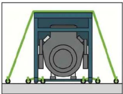
natural_image
Diagram of a mechanical device with green support frames and a central circular component (no text or symbols)text_image
Safety warning illustration showing a pump nozzle, no smoking, and hazard symbol with text labelsnatural_image
Simple line drawing of a boat hull with an arrow indicating direction (no text or symbols)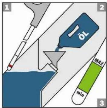
text_image
1 2 10 MAX min 3natural_image
Illustration of a hand reaching for a mechanical component with water droplets, next to a warning sign (no text or symbols)natural_image
Close-up of a mechanical device with two blue electrical connectors and a yellow label (no readable text or symbols)natural_image
Mechanical assembly diagram showing a tool interacting with a bolt and nut (no text or symbols)text_image
Close-up of a red vehicle engine compartment with warning signs and safety symbols on the lower paneltext_image
Close-up of an orange industrial machine with warning labels and safety symbols on the covernatural_image
Close-up of a red tractor with visible exhaust pipe and control panel (no text or symbols)declare under our sole responsibility that the product to which this declaration relates is in conformity with the following relevant regulations
and subsequent modification and integrations
measuring procedure according to ISO 3744 (part110)
conformity assessment procedure according to 2000/14/EC procedure VIII. (notified body)
Directorate General Environment
BUI-9 06/204 - B-1049 Brussels
Belgium
verantwortlich
authorized by
le responsable
el responsable
natural_image
Red and black industrial machine with visible wheels and a labeled number 97-08 (no text or symbols on the device itself)natural_image
Red professional gas turbine machine with visible internal components and branding (no text or symbols on the device body)ESE 206 HS-GT
Kataloški br. 112300
ESE 406 HS-GT
Kataloški br. 112302
ESE 506 DHS-GT
Kataloški br. 112304
ESE 606 HS-GT ES
Kataloški br. 112307
ESE 606 DHS-GT ES
Kataloški br. 112308
ESE 306 HS-GT
Kataloški br. 112301
ESE 406 HS-GT ES
Kataloški br. 112306
ESE 606 HS-GT
Kataloški br. 112303
ESE 606 DHS-GT
Kataloški br. 112305
text_image
Labeled diagram of an industrial power plant with numbered components and warning labelsCrtež 2.1: Naljepnice na generatoru
1 Napomena o razini zvučne snage
text_image
Safety warning symbols including checkmark, warning triangle, and exclamation mark on a documentNošenje generatora
- Uređaj uhvatite za nosivi okvir.
- Podignite gæerator.
- Prenesite generator na mjesto rada.
- Postavite generator.
- Otpustite nosivi okvir.
√ Generator je prenesen na svoje mjesto rada.
4.2 Postavljanje generatora
Za postavljanje generatora postupite prema sljedećim uputama.
Zahtjevi Ovi se zahtjevi moraju u cijelosti ispuniti:
• Ravna i čvrsta podloga natvorenom.
- Bez prisutnosti zapaljivih materijala na mjestu rada.
- Bez prisutnosti eksplozivnih materijala na mjestu rada.
- Uređaj mora biti slobodno postavljen (ne smije biti pokriven).
OPREZ!
Curenje motornog ulja i goriva može zagaditi tlo i podzemne vode.
- Spriječite curenje motornog ulja i goriva.
natural_image
Illustration of a mechanical device with a warning sign and smoke, no text or symbols present.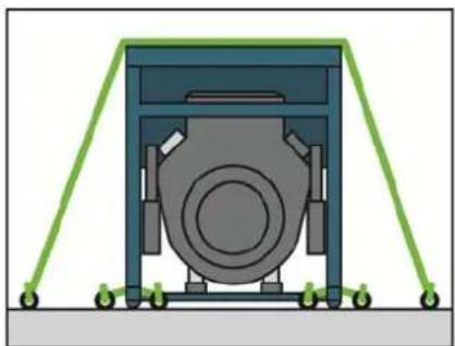
natural_image
Diagram of a mechanical device with green support frames and a central circular component (no text or symbols)text_image
Safety warning illustration showing exhaust fuel, no smoking, and hazard symbol with Chinese labelsnatural_image
Simple line drawing of a boat hull with an arrow indicating direction (no text or symbols)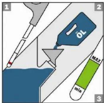
text_image
1 2 OL MAX min 34.5 Pokretanje generatora
Za pokretanje generatora postupite prema sljedećim uputama.
Zahtjevi Ovi se zahtjevi moraju u cijelosti ispuniti:
- Izvedena provjera i ispitivanje električne sigurnosti.
• Pun spremnik goriva.
• Zadovoljava juća količina ulja.
• Dovoljan dovod zraka i prozračivanje. - Aparati isključeni ili odvojeni.
OPREZ!
Radne tekućine mogu se zapaliti ili eksplodirati.
- Spriječite curenje motornog ulja i goriva.
- Ne koristiti sklopove za potpomaganje pokretanja.
- Izbjegavajte otvoreni plamen i iskre.
Uspostavljanje dovoda goriva
Gorivo se dovodi iz vlastitog spremnika na generatoru.
text_image
(1) (2) (3)Crtež 4.1: Otvorite / zatvorite slavinu goriva
| Položaj prekidača | Upotreba | Položaj |
| ISKLJUČENO | zatvoreno | vodoravno |
| UKLJUČENO | otvoreno | uspravno |
Tablica 4.1: Prebacite položaj slavine goriva.
natural_image
Illustration of a hand reaching into a mechanical device with water droplets, warning symbol, and warning sign (no text or labels)RUČNO POKRETANJE Motor pokrenite na sljedeći način:
- Potisnite čou položaj za pokretanje (pogledajte natpis na filtru zraka, samo kod hladnog motora).
- Prekidač motora postavite u položaj "ON" (UKLJUČENO).
- Polako povlačite uže za pokretanje dok ne osjetite napetost, a zatim ga naglo povucite.
√ Motor se pokreće.
Da biste olakšali povlačenje, drugom se rukom pridržavajte za uređaj.
- Postavite čok u osnovpioložaj.
√ Motor je pokrenut.
ELEKTRIČNO POKRETANJE
-
Potisnite čok u položaj za pokretanje (pogledajte natpis na filtru zraka, samo kod hladnog motora).
-
Zakrenite kontaktni ključ do kraja udesno u položaj START dok se motor ne pokrene, a zatim ga otpustite.
√ Motor se pokreće.
natural_image
Close-up of a mechanical device with two blue electrical connectors and a yellow label (no readable text or symbols)natural_image
Mechanical assembly diagram showing a tool interacting with a bolt and nut (no text or symbols)Crtež 4.4: Uklonite čep za drenažu ulja.
text_image
Close-up of a red vehicle engine compartment with warning signs and safety symbols on the hoodCrtež 4.5: Zatvorite slavinu goriva.
OPREZ!
Proliveno gorivo može se zapaliti ili eksplodirati.
text_image
Close-up of an orange industrial machine component with warning labels and safety symbolsnatural_image
Close-up of a red tractor with visible exhaust pipe and control panel (no text or symbols)Crtež 4.7: Uklonite filtar za zrak.
- Uklonite pokrov filtra iz kućišta filtra za zrak.
- Uložak filtra za zrak očistite u odgovarajućoj posudi pomoću tople vode i deterdženta ili pomoću nezapaljivog benzina za čišćenje.
- Na filtar izlijte ulje, a zatim istisnite višak.
- Vratite natrag filtar za zrak.
- Vratite pokrov filtra na kućište filtra za zrak.
√ Filtar za zrak je očišćen i postavljen.
Tel: +49(0)7123-9737-44
E-pošte: service@endress-generators.de
and subsequent modification and integrations
measuring procedure according to ISO 3744 (partII0)
conformity assessment procedure according to 2000/14/EC procedure VIII. (notified body)
procede d'evaluation de conformite 2000/14/EC procedure VIII. (organisme avise:)
Directorate General Environment
Unit C.1 "Air, None & Transport"
Belgium
verantwortlich
authorized by
le responsable
el responsable