
ESE 110 IW/RS - Generator Endress - Free user manual and instructions
Find the device manual for free ESE 110 IW/RS Endress in PDF.


| Product Type | Portable Generator |
| Brand | Endress |
| Model | ESE 110 IW/RS |
| Dimensions (L x W x H) | 600 mm x 400 mm x 500 mm |
| Weight | 45 kg |
| Power Output (Rated) | 1.1 kW (1.1 kVA) |
| Voltage | 230 V AC |
| Frequency | 50 Hz |
| Fuel Type | Gasoline |
| Fuel Tank Capacity | 5.0 L |
| Run Time at 50% Load | 8 h |
| Start Type | Recoil Start |
| Noise Level | 65 dB(A) at 7 m |
| Output Sockets | 1 x AC 230 V, 1 x DC 12 V |
| Engine Type | 4-Stroke, Air-Cooled |
| Oil Capacity | 0.6 L |
| Maintenance | Check oil and air filter every 20 hours; change oil after first 20 hours, then every 100 hours |
| Safety Features | Low oil shutdown, overload protection, earth leakage circuit breaker |
| Spare Parts Availability | Through Endress authorized dealers |
| User Manual | Free PDF download on notice-facile.com (78 pages) |
Frequently Asked Questions - ESE 110 IW/RS Endress
User questions about ESE 110 IW/RS Endress
0 question about this device. Answer the ones you know or ask your own.
Ask a new question about this device
Download the instructions for your Generator in PDF format for free! Find your manual ESE 110 IW/RS - Endress and take your electronic device back in hand. On this page are published all the documents necessary for the use of your device. ESE 110 IW/RS by Endress.
USER MANUAL ESE 110 IW/RS Endress
ESE 67 IW/RS Item No. 333363 / 333373
ESE 90 IW/RS Item No. 333364 / 333374
ESE 110 IW/RS Item No. 333365 / 333376
Publication date June 2021
Copyright
This documentation and parts thereof are subject to copyright. Any use or modification beyond the restrictions of the Copyright Act is forbidden and subject to penalty without the consent of ENDRESS Elektrogerätebau GmbH.
This applies in particular to copies, translations, microfilming, as well as storage and processing in electronic systems.
Notes on printing
All descriptions, technical details and illustrations refer to the version of the generator for printing.
We reserve the right to make modifications in terms of ongoing technical development. This operating manual does not include technical modifications that occurred after printing.
The colours in this operating manual do not always comply completely with the actual designs due to technical printing reasons.
Table of Contents
1 Directories ....5
2 About this manual 6
2.1 Constituent parts of the documentation....6
2.2 Using this operating manual 6
3 Product identification 9
3.1 Welcome to ENDRESS! 9
3.2 Your product 9
3.2.1 A device description and intended use 9
3.2.2 Foreseeable misuse 10
3.3 Scope of delivery of your generator....12
3.4 Labels on the generator....13
4 For your safety....16
4.1 Safety symbols 16
4.2 General safety instructions .....18
4.3 Residual risks 18
4.4 Authorised operating personnel – qualifications and obligations....23
4.5 Danger zones and work areas....23
5 Checking the electrical safety .....25
6 Description of the device 27
6.1 Views....27
6.2 Exhaust gas and battery side components .....28
6.3 Components on the maintenance side .....29
6.4 Components for operating panel and switch box 30
7 Commissioning ....32
7.1 Transporting and preparing your generator....34
7.2 Refuelling your generator 35
7.3 Starting the generator 36
7.4 Low load diesel engine operation 37
7.5 Turning off your power generator 38
7.6 Turn off your generator in the event of an EMERGENCY....38
7.7 Connection of power consuming equipment 40
7.8 Residual current circuit breaker (RCD) 43
8 The device in-use....46
8.1 Operating the E-MCS 7.0 control module .....46
8.1.1 Operating panel for control module E-MCS 7.0 .....47
8.1.2 Display window on the control module's screen . . . . . . . . . . . . . . . . . . . . . . . . . . . . . . . . . . . . . . . . . . . . . 49
8.2 Select operating mode (II / TN-S) 50
8.2.1 Direct supply mode 51
8.2.2 Building supply operating mode .....51
8.3 Insulation monitoring 54
8.4 2-way fuel valve....56
8.5 HARTING remote starting device ....58
9 Optional fittings....60
9.1 Powerlock-Box....60
9.2 Dummy load 61
9.3 External battery charging....62
10 Maintenance....64
10.1 Maintenance plan 64
10.2 Maintenance work....64
10.3 Starter battery 65
10.3.1 Replacing the battery 65
10.4 Engine oil....66
10.4.1 Changing the engine oil....66
10.5 Checking the coolant....68
11 Storage 69
12 Disposal 70
13 Troubleshooting....71
14 Technical data 73
15 Replacement parts....75
Keyword index 77
1 Directories
1.1 List of illustrations
Fig. 3-1 Example of a type plate .9
Fig. 3-2 Included with delivery .12
Fig. 3-3 Labels on the device .13
Fig. 6-1 Views of the generator .27
Fig. 6-2 Components on the connecting side .28
Fig. 6-3 Components on the maintenance side .29
Fig. 6-4 Components for operating panel and external switch box .30
Fig. 7-1 Setting up personal protection measures (source: DGUV) .33
Fig. 7-2 Manually starting and stopping the power generator .36
Fig. 7-3 Connecting consumers .41
Fig. 7-4 Built-in types of residual current circuit breaker (RCD) .44
Fig. 7-5 Differential current release .45
Fig. 8-1 Control module's display .46
Fig. 8-2 Control module's control panel .47
Fig. 8-3 Operating display on the control module .48
Fig. 8-4 Sample from control module's display screen .50
Fig. 8-5 TN system / TT system version example .53
Fig. 8-6 Insulation monitoring .55
Fig. 8-7 Refuelling device connection .57
Fig. 8-8 Remote starting device with HARTING® socket .59
Fig. 9-1 POWERLOCK BOX .60
Fig. 9-2 Display with dummy load operating .61
Fig. 9-3 230 V feed plug for battery charger .62
Fig. 10-1 Starter battery (illustration similar) .65
Fig. 10-2 Manual oil scavenger pump .67
Fig. 10-3 Checking the coolant .68
Fig. 15-1 Spare parts over endressparts.com .75
1.2 List of tables
Tab. 3-1 Labels on the device .15
Tab. 4-1 Danger zone on Generators .24
Tab. 5-1 Recommended test intervals .26
Tab. 8-1 Control buttons on the control module .48
Tab. 8-2 Operating display on the control module .49
Tab. 13-1 Troubleshooting .72
Tab. 14-1 Power generator technical data .73
2 About this manual
We would like to explain to you the safe and correct use of your generator in the best possible way through this operating manual. To do this we have oriented ourselves to the new European standard DIN EN 82079-1 for preparing the user manuals.
It is absolutely essential for safe and appropriate use that you read through this manual very carefully and understand it before using the device for the first time.
Your observance of it creates the foundation for,
- avoiding dangers for yourself and others,
- reducing repair costs and downtimes as well as
• increasing the reliability and service life of the generator.
Not only this manual but also the laws, regulations, guidelines, and standards applicable in the country of use must be observed.
This document only describes the safe operation of the generator when used as a complete unit. The following also includes detailed technical operating instructions that are binding with regard to using the device's specific components.
This documentation and also the product described in it are subject to a continuous improvement process. In doing this we ensure that the full product is compliant with the current safety requirements and the current state-of-the-art. The respective most up to date language version of the operating manual and the original operating manual can be found on our website
www.endressparts.com
2.1 Constituent parts of the documentation
Apart from this operating manual, the following documents are part of your device's complete documentation:
- Operating and maintenance manual for the engine (FPT-Iveco)
- Documentation of the electrical generator (MECC ALTE company, on CD-ROM)
- Generator circuit diagram
- Starter battery handling instructions (electric start)
• EU Declaration of Conformity - Generator test report
- POWERLOCK BOX operating and maintenance manual (optional)

NOTICE!
The complete documentation is an integral part of the device and you must adhere to it.
▶ All of the integral parts of the documentation must always be accessible to the operating personnel and they should be kept with the device.
2.2 Using this operating manual
In order to increase the legibility, comprehensibility and transparency of the document, certain information is highlighted or identified according to a uniform system. The following particularly belong in this category:
signs warning about dangers to life and limb
Safety and warning notices are necessary at all locations where there is potential danger from the device which cannot be eliminated by design or operational measures. We restricted ourselves to the permitted minimum in order to place the required distinctive warning notices at the correct point in time without impairing the legibility and comprehensibility of the operating manual. This is according to the regulations contained in the international standard DIN ISO 3864 describes a fixed rule for all safety and warning notices, as shown in the following example.
Examples:
Signal Word
Hazard Type
Hazard Consequence
▶ Hazard Avoidance

DANGER!
Electrical voltage
Risk of suffering potentially deadly electrocution by touching live parts
▶ Only use undamaged connecting lines
▶ Avoid all damp / wetness when connecting consumers
▶ Never operate the power generator with an opened control panel

The standard mentioned classifies the safety risks according to different risk potentials. To understand and avoid dangers to one's health and even life, please be sure to read the explanations given in Chapter 4.1.
Safety symbols
These warning notices are usually used in a safety symbol which also emphasises the type of danger; see next example. A list of the safety symbols used in this operating manual can be found in Chapter Fig. 3-1. The safety symbols never stand alone.
Notices on avoidance of damage to the device
According to DIN ISO 3864, notices which warn against false operation and possible damage to the device or to the equipment used should be clearly distinguishable from previously named warning notices in as far there is no danger to health. An example of such a notice can be seen here:
Signal Word
Type and Consequence of Improper Use
▶ Intended Use
NOTICE!
Use of wrong or outdated fuel damages or destroys the engine.
▶ Only use released diesel fuel.
▶ Observe the shelf life of the fuel according to the supplier.
▶ Observe the Operating manual from the engine manufacturer
Symbols and formatings in the text
In order to increase the legibility, comprehensibility and transparency of the document, various information and activities are awarded uniformly repeating bullets or formatings. The following example shows presentation of a sequence of actions with established work steps:
Example:
√ Prerequisites which must be fulfilled before starting any sequence of actions
- Action steps according to a fixed sequence.
- The action steps must be fully completed.
- The sequence must be observed.
Results of the action which should be achieved after performing the sequence of action.

Additional notices for operation or for function of a unit are marked with the adjacent symbol.

NOTICE!
The adjacent symbol is situated anywhere where the supplier documentation must be read and observed and refers to,
▶ appropriate information,
▶ tasks or
▶ action steps.
References to details and components in figures are made with blue bordered position numbers in the text such as the example of CE signs on the type plate demonstrates, see Fig. 3-1.
3 Product identification
3.1 Welcome to ENDRESS!
We are pleased that you have made the decision to purchase a ENDRESS power generator. You have purchased a high-performance product into which we have embodied decades of our experience and have integrated many functions oriented on daily use. Through careful selection of high quality components and materials in combination with the proverbial Swabian engineering performance you have in your possession a device which will operate reliably for many years, also under the hardest of operating conditions.
3.2 Your product
Customer service
In order to precisely identify your device there is a type plate attached to the Generators (see Fig. 3-1), which includes details about the device designation and "S/N" serial number. If you have any questions about device details, functions or notices concerning operation, please contact our
Customer service: Tel. +49 (0)7123 9737-44
Email: service@endress-stromerzeuger.de
You will find competent contact persons there, also concerning original spare parts and wear parts. (see also Chapter 15)
Type plate
The type plate shown below is a representation of the adhesive label placed on the device. Please be prepared, when contacting our service team, to assist us in exactly identifying your device. Refer to your generator's operating instructions for further information about finding the type plate.

3.2.1 A device description and intended use
As part of network backup, the power generator creates electricity that can be used in alternating operation as an “on-site operation” OR as a “building supply” (IT-TN version).
Your power generator creates electricity for the "on-site operation" mode as part of a network backup operation, through which you can supply a mobile distribution system with electricity. This enables mobile use of commercially available electrical devices with single-phase 230 V AC / 50 Hz or three-phase 400V AC / 50 Hz (depending on the equipment being used).
Your power generator has been designed for manual or automatic operation (remote start) with one or more electrical consumers. To protect against electric shock (i.e. current flowing through your body), automatic switch-off according to DIN VDE 0100-551: 2017-02 is used as the protective separation measure. The protective conductor system from the attached consumers will take over the earthing function. The terminal strip (Fig. 6-4) is used for connecting a suitable earth (e.g. an earthing stake). Proper is needed and it must be done by a qualified electrician.
In "building supply" mode (see Chapter 8.2, the power generator serves as an emergency power supply for a stationary system through a flexible cable connection. For this, there is a separate CEE 400 V / 50 Hz socket with white colour marking.
Your generator consists of an AC generator driven by a combustion engine that is bolted onto it. This unit is mounted elastically inside a closed, sound-insulated housing, and vibration dampers are used to ensure low vibration.
The unit generates AC (three-phase) current with a nominal voltage of 400 V at 50 Hz. More detailed technical data can be found in Chapter 14. An integrated voltage regulator ensures that the stability of the generated voltage is within the nominal rotational speed range. Power is taken through a spray-water-protected Schuko socket with nominal voltage of 230 V / 50 Hz 1\~ or CEE sockets for 230 V / 50 Hz / 1\~ or 400 V / 50 Hz / 3\~ (see Fig. 6-4).
The generator is only to be used outdoors within the indicated voltage, output, and nominal RPM ranges (see type plate).
The power generator must never be used for direct feed into other power distribution systems (e.g. public power supply) or be used with other power generation systems (e.g. other power generators).
The generator is not to be used in explosion-prone environments.
The generator is not to be used in environments where there is a risk of fire.
The generator must be operated according to the specifications in the technical documentation.
Every inappropriate use or all activities on the generator that are not described in this manual is prohibited misuse beyond the manufacturer's legally defined limits of liability.
3.2.2 Foreseeable misuse
Apart from the description of appropriate use, the lawmaker also requires concrete references to the results of “reasonably foreseeable misuse”. In a case of incorrect use or inappropriate handling of the generator the manufacturer's EU Declaration of Conformity, and automatically thereby also the operating licence, are nullified. For products with a manufacturer's warranty the manufacturer will reject any claims made under warranty for damages which were caused by misuse and its direct as well as indirect consequences.
In particular unauthorised misapplications include:
• operation of the generator takes place without valid checks for
- electrical safety
– checking that the stipulated servicing and maintenance work has been done
- operation of the generator taking place without the protective equipment installed by the manufacturer
- constructional or electrical modifications were made to the generator
- software was modified or changes were made to the generator's factory settings
- use of the generator by inadequately instructed operating personnel
Furthermore at all costs avoid the following Misuses:
- Never refuel the generator's own tank when the engine is running. The vibrations and strong exhaust streams during operation can lead to fuel spillage. This leads to an increased risk of explosion and fire and therefore danger to operating personnel, the environment and the device.
- Never refuel the generator's own tank when it is hot. Overflowing fuel and exhaust fuel vapours can ignite on hot parts of the device.
- Never open the generator's tank cover whilst it is running or if it is hot. Overflowing hot fuel and escaping fuel vapours can ignite on the device's hot parts.
- The generator is never to be connected up to another energy distribution system (e.g. public power supply) or to other power generating systems (e.g. other generators, solar plants, etc.). To start with this is usually not permitted by . In both cases this will inevitably lead to severe damage and possibly also severe injury.
- Never place the generator in explosion-prone environments. The individual components of the generator are not designed to be EX-protected.
- Never operate the generator in rooms, narrow pits or vehicles. The combustion exhaust gases contain poisonous substances including the odourless but deadly gas carbon monoxide (CO) which, when breathed in, can accumulate in cases of poor air circulation to reach deadly concentrations. Also a lack of fresh air circulation leads to overheating and possible damage to the generator right through to destruction.
- For the same reasons of risk, never divert exhaust gases for the purposes of heating rooms or vehicles.
- Never clean the generator with the aid of a high pressure cleaner or a strong jet of water.
- Never allow water to find its way inside the generator. Never pour water over the generator and never clean it using a water hose or a high pressure cleaner.
- Never operate the generator in any area where it could be flooded by high water or any other events. The device's protection class (see Chapter 14) allows operation with spray water, however not in the case of floods.
3.3 Scope of delivery of your generator
Apart from the technical documentation mentioned in Chapter 2.1 the following items are Scope of delivery of your generator:

Fig. 3-2 Included with delivery
| Item Name | |
| 1 | Earth stake with connection cable |
| 2 | Key for POWERLOCK BOX (optional) |
| 3 | Universal key for access hatch |
| 5 | Filling aid with hopper |
| 6 | Technical documentation, see Chapter 2.1 |
3.4 Labels on the generator
An important part of the operating manual is the labelling and notices on your generator. These labels must not be removed and must always be maintained in legible condition. If there is damage to a Labels can be ordered from our customer service team. The following figures and tables show the stipulated attachment point and a brief explanation of the labels.

Fig. 3-3 Labels on the device
| Item | label Meaning | |
| 1 |  | Mandatory signRead the operating manual before starting up |
| 2 | ATTENTION! WORK WITH CLOSED HOOD ACHTUNG! MIT GESCHLOSSENER HAUBE ARBEITEN ATENCIÓN! TRABAJAR CON EL GRUPO CERRADO ATTENTION! TRAVAILLER AVEC CAPOT FERMÉ ATTENZIONE! LAVORARE A COFANO CHIUSO | NoteOperate the power generator only with the maintenance hatches closed. |
| 3 |  | NoteCrane loading lugExample of maximum device weight |
| 4 |  | NoteNoise emissions |
| 5 |  | WarningBurn hazardHot surfaces |
| 6 |  | Type plateExample: |
| 7 | 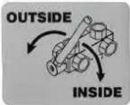 | Note2-way fuel valveExternal tankInternal tank |
| 8 | Dieselkraftstoff nach DIN EN 590Biodiesel-Anteil <10%Tankhalt ca. 960 |ACHTUNG:NICHT WÄHREND DES BETREBES NACHTAIKEN, ZUM NACHTAIKEN, MOTOR ABSTELLEN UND EINIGE MINUTEN ABKÜHLEN LASSEN. | NoteFuel qualityand tank contents |
| 9 |  | Prohibition signsNo smoking!Open flame prohibited! |
| 10 |  | POWERLOCK stickerOpen, connect and disconnect only when de-ener-gized. |
| 11 |  | The connection terminal is for potential equalization (left) with IT networks and for earthing (right) with TN networks. |
| 12 |  | DGUV instruction onGeneratorsof Version C |
| 13 |  | Death hazardLive parts when opening the cover |
| 14 |  | The EMERGENCY STOP switch turns off the power generator immediately if there is an emergency. |
| 15 |  | Warning symbolsDangerous voltageFor electricians only |
| 16 |  | Brief operating manual |
| 17 | 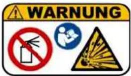 | Warning noticesDo not use starting aids!Explosion hazard |
Tab. 3-1 Labels on the device
4 For your safety
The following chapter describes basic Safety instructions for safe operation of your generator. Your device is a very high-performance electrical machine which is potentially dangerous when operated if it has not been installed, commissioned, used, serviced and repaired according to the operating manual. If necessary, the operating manual will also include different supplements that depend on the country of use, in addition to the present one.
Operation, use, servicing as well as any work with or on the generator is therefore only permitted by such persons who have read this chapter and have put its provisions into practice!
Concrete warning notices can also be found regarding basic safety instructions further on in this operating manual. These are always placed in an explanatory text immediately before the description of work steps which can be dangerous if the warning notice is not observed. Read the following sections for correct and rapid understanding of these safety and warning notices. They describe their systematic structure as well as the meaning of markings and symbols.
4.1 Safety symbols
The safety symbol indicates graphically that a source of danger exists. We use the internationally valid safety symbols from ISO 7010 for rapid and unique classification of the respective dangerous situation. In the following there is a description of the warning symbols used in this operating manual with an explanation about the respective dangerous situations.

Warning of a general hazard
This warning symbol indicates activities where several causes can lead to risks. The concrete danger must be respectively more clearly specified by further notices.

Warning of a dangerous electrical voltage
This warning symbol is indicates activities where the danger of electric shock exists, possibly with lethal consequences.

Warning of potentially explosive materials
This warning symbol indicates activities where the danger of an explosion exists, possibly with lethal consequences.

Warning of toxic substances
This warning symbol indicates activities where a risk of poisoning exists, possibly with lethal consequences.

Warning of corrosive substances
This warning symbol indicates activities where a risk of chemical burns to the environment as well as people exists, possibly with lethal consequences.

Warning of environmentally damaging substances
This warning symbol indicates activities where a risk of contaminating the environment exists, possibly with catastrophic consequences.

Warning of hot surfaces
This warning symbol indicates activities during which there is the danger of burns, possibly with lasting consequences.

Warning of a suspended load
This warning symbol indicates activities where the danger of falling loads exists, possibly with lethal consequences.

Warning of automatically starting machines
This warning symbol indicates activities where a danger of being injured by self-starting machines exists, possibly with lethal consequences.
4.2 General safety instructions
ENDRESS Generators are designed to operate electrical equipment with appropriate power output requirements. Other uses can lead to severe injury to operating personnel and people nearby. There is also increased risk of damage to the generator and further property damage.


DANGER!
Mortal danger due to an electric shock if live parts are touched.
▶ Never operate the device if it is in a damaged condition.
▶ Never operate the electrical consumers and connecting cable (power consuming equipment) in a damaged condition.
▶ Never feed directly into existing networks that are already connected to a power source (e.g. power supplier, solar plant, etc.).
▶ Never operate the device with wet hands.
Most injuries and equipment damage can be avoided if all instructions given in this manual and all instructions attached to the device are followed.
The Generators must not be modified in any way, not even temporarily. This pose a death hazard to operating and deployed personnel and damage to the generator and the consumers being used.
Operating company and Operating personnel are to use the Generators only according to regulations contained in the entire technical documentation (hereinafter referred to as appropriate use).
Every instance of inappropriate use and all activities on the Generators that are not described in this manual are prohibited misuse beyond the legally defined limits of the manufacturer's liability. In return all claims for damages and warranty claims against ENDRESS-Elektrogerätebau GmbH that are associated with misuse are null and void.
4.3 Residual risks
As a manufacturer of EU-compliant machines, ENDRESS make great efforts to create designs which already eliminate possible risk potentials at the design stage. If this is not possible without significantly impairing the functions of a device, we implement suitable protective measures protect the user from injury.
If there are still some residual risks associated with working with the device, we clearly advise the user about these sources of danger, possible consequences as well as measures to avoid such dangers.
The residual dangers were analyzed and Residual dangers identified during the development and design of your Generators by means of a danger analysis according to DIN EN 60204, DIN EN ISO 12100 and DIN EN ISO 8528-13.
References to general sources of danger can be found in chapters 4 and 5. From Chapter 6 one can find concrete warning notices placed before every action step which represents a residual risk.
The exact structure and contents of warning notices are defined in the ISO 3864 series of standards and follow an established identification marking required to immediately be able to estimate the degree of the respective danger. Exactly impress upon yourself the identification marking of the
four different danger levels in order to be able to reliably assess the dangers associated with the individual operating states and action steps when reading the operating manual.

DANGER!
DANGER describes a danger which represents a high level of risk, which can lead to death or severe injuries, when not avoided.
▶ The individual points provide instructions and
▶ notices as aids to avoid the danger
▶ or to reduce the risk to an acceptable level.

WARNING!
WARNING describes a danger which represents a medium level of risk, which can lead to death or severe injuries, when not avoided.
▶ The individual points provide instructions and
▶ notices as aids to avoid the danger
▶ or to reduce the risk to an acceptable level.

CAUTION!
CAUTION describes a danger which represents a low level of risk, which can lead to minor or medium level injuries when not avoided.
▶ The individual points provide instructions and
▶ notices as aids to avoid the danger
▶ or to reduce the risk to an acceptable level.
NOTICE!
ATTENTION! describes a situation or action that might result in damage to equipment and/or malfunctions if it is not prevented.
▶ The individual points provide instructions and notices
▶ as an aid to avoid or prevent damage to equipment.

DANGER!
Mortal danger due to an electric shock if live parts are touched.
▶ Never operate the device if it is in a damaged condition.
▶ Never operate the electrical consumers and connecting cable (power consuming equipment) in a damaged condition.
▶ Never feed directly into existing networks that are already connected to a power source (e.g. power supplier, solar plant, etc.).
▶ Never operate the device with wet hands.


DANGER!
Engine exhaust gases contain poisonous and partially invisible gases such as carbon monoxide (CO) and carbon dioxide (CO2).
Risk of death due to poisoning or asphyxiation.
▶ Ensure that there is good ventilation during the whole period of operation.
▶ Only operate the generator in the open.
▶ Never direct the exhaust gases into rooms or pits.

DANGER!
Danger of severe or mortal injuries being incurred from falling loads.
▶ Never stand under or close to a suspended load, also not to provide assistance.
▶ Ensure that there is no person in the area of swivel of the lifting device.
▶ Use all suitable measures to prevent the suspended load from swaying.

DANGER!
Leaking engine oil and fuel can burn or explode.
A risk of suffering severe even deadly burns.
▶ Prevent engine oil or fuel from leaking out.
▶ Never open the tank cover during operation or when it is hot.
▶ Remove leaked operating fluids immediately and appropriately.
▶ Never use an additional starting aid.
▶ Smoking, naked flames and sparks are forbidden.
! DANGER!
Hot parts can ignite flammable and explosive materials.
A risk of suffering severe even deadly burns.
▶ Never operate the generator in the vicinity of combustible or flammable materials.
▶ Never operate the generator in an environment prone to an explosion.

! WARNING!
There is a risk of explosion and fire in the case of inappropriate handling and spark development when working with the battery.
Danger from spraying sulphuric acid. Danger of suffering severe even deadly burns and chemical burns. Danger of being blinded.
▶ Never lay electrically conductive parts on the starter battery.
▶ Flames, sparks, an open light and smoking are prohibited.
▶ Avoid sparks when handling cables and electrical devices, as well as electrostatic discharge.
▶ Avoid short-circuits.
▶ Wear acid-resistant protective clothing.

! WARNING!
Escaping corrosive acid fumes or sulphuric acid during and after the charging process. A risk of suffering severe or even deadly burns.
▶ Only work with acid-resistant protective equipment.
▶ Clean surfaces covered in acid immediately using adequate amounts of water.
▶ Only charge the starter battery in a well ventilated environment.

CAUTION!
Certain surfaces on the device can get very hot whilst it is running.
Risk of burns
▶ Never touch any engine parts (in particular the exhaust system) for a few minutes after ceasing operation.
▶ Always leave hot engine parts to cool down before touching them.

CAUTION!
A high device weight. Risk of crushing from improper handling during operation or transport.
▶ Only lift the generator with the aid of all handles provided or by using a suitable hoist.
▶ During transport on vehicles, ensure that there is the prescribed load securing in place.
▶ With it in a raised condition, never come close to or stand under the generator.

NOTICE!
Leaking engine oil and operating fluids can contaminate the soil and groundwater.
▶ Ensure that the generator is transported horizontally and mounted.
▶ Make all efforts, at all costs, to prevent escaping of operating fluids.
▶ Dispose of contaminated soil immediately and according to regulations.


NOTICE!
Use of wrong or outdated fuel damages or destroys the engine.
▶ Only use the fuel displayed on the sign (Tab. 3-1).
▶ Observe the possibly enclosed documentation for the fuel release of the engine manufacturer
▶ Observe the shelf life of the fuel according to the supplier.
▶ Observe the engine operating manual.

NOTICE!
Excessive heat or moisture can destroy the device.
▶ Always ensure that there is a good supply of air and heat removal.
▶ Never operate the generator in rooms or narrow pits.
▶ Never clean the device with the aid of a strong jet of water or high pressure cleaner.
▶ Never allow water to find its way inside the generator.
4.4 Authorised operating personnel – qualifications and obligations
Your Generators is a complex machine, the operation and maintenance of which requires exact knowledge of its functions and danger potentials. Therefore any work with or on the device, of any kind, may only be performed by authorised and instructed operating personnel.
Quite apart from the authorisation which the operating company of the device must issue, only such persons may operate or service the device who fulfil the following criteria. They are designated in this operating manual as operating personnel.
The authorised operating personnel must:
- be of age.
- be trained in First Aid and be able to provide it.
- be familiar with the accident prevention regulations and safety instructions relevant to the Generators and be able to apply them.
• have read Chapter 4, have understood the contents and are able to use and implement them in practice. - be trained and instructed according to the rules of conduct in the case of malfunctions.
• have the physical and mental abilities to carry out their responsibilities, tasks, and activities on the Generators. - be trained and instructed in their responsibilities, tasks and activities on the Generators.
• have understood the entire technical documentation concerning their responsibilities, tasks and activities on the Generators and be able to implement these in practice.
4.5 Danger zones and work areas
In order to be able to consider all of a machine's safety aspects and to comply with the safety and health protection requirements of the applicable standards and EU directives, we have assessed the use of your Generators in all of the phases that it will go through during its product service life (product life cycle). The following zones were defined on the Generators for this purpose: The danger zones and work places (work areas) around the generator are determined by the activities to be undertaken within the various phases in individual life cycles:
- Working zone: In this zone on and around the Generators (approx. 1 metre radius) the trained operating personnel (see Chapter 4.4 ) may operate and inspect the device in compliance with all of the safety and operating instructions given in the technical documentation. All other people (especially minors and people with disabilities) must remain outside this working zone.
- Danger zone: This zone must be kept free of all personnel during all phases of use and service life of the device. Any work in this zone is only to be undertaken by specially trained specialists if it is essential for the fulfilling of the task and if all of the protective equipment (PPE) needed is used. You must always comply with the following limits:
| Product's service life phase Danger zone | |
| Transport and installation | within a radius of 1m around or below the device |
| Operation within the outer limits of the device | |
| Service and maintenance | Within the outer limits of the device when switched on Generators |
Tab. 4-1 Danger zone on Generators
5 Checking the electrical safety
Checking electrical safety requires different measures that are only to be taken by authorized personnel. In doing so the pertinent VDE provisions, EN and DIN standards, in their valid versions, must be observed. For use at construction or assembly sites, the DGUV Information 203-032 edition of May 2016 must be observed. It defines special protective measures and rules of conduct for the commissioning and corresponding marking on the device.
You must especially never use defective or damaged consumers, cable connections or plug connectors, etc. (current-consuming equipment). They must be checked for proper condition at regular intervals (see Tab. 5-1)
On-site operation
earthing
The "on-site operation" mode (see Chapter 8.2.1), has been designed for manual or automatic (remote start) operation with one or more electrical consumers. To protect against electric shock (current flow through your body), the protective separation measure with equipotential bonding according to DIN VDE 0100-551:2017-02 is used. The protective conductor system of the attached consumer equipment takes over the function of the potential equalization device. The terminal (Fig. 6-4) is connected with this Potential equalization device connected. An earthing device is not needed in the "on-site operation" mode.
Your Generators corresponds to a Version A generator according to DGUV Information 032-203 issued in May 2016 when it is in "on-site operation" mode. A corresponding marking can be found on the device (see Fig. 3-3):
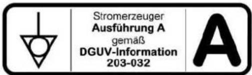
We strongly recommend that you also comply with the requirements of DGUV Information 203-032 for other purposes.

DANGER!
Dangerous electrical voltages will be present if several consumables are connected up without a working personal safety device.
Mortal danger from electrocution
▶ Never operate multiple consumables from the Generators without additional RCDs (residual current circuit breaker) for the second and each additional consumable.
▶ Check the personal protection according to the check intervals given in Tab. 5-1.
earthing
Supplying power to a building
In "building supply" mode (see Chapter 8.2.2) your Generators has been designed as a replacement network supply for feeding into stationary installations such as residential houses or public facilities. Suitable on-site protective measures must be implemented to protect against electric shock (current flow through your body). The generator is earthed through the power supply cable's and this earths the stationary system.
In addition to the details given above, the electrical safety of the Generators is to be checked by a qualified electrician at regular intervals. The periods between testing must be established in such a way that the Generators and all work equipment to be connected can, based on current general knowledge, operational experience or specific evidence, be safe to use in the period between the two inspections. (Examples in TRBS 1201, implementation instructions for §5 of BGV/GUV-V A3, BGI 594, BGI 608, Appendix 2, recommendation of BGI/GUV-I 5090 "Repeated testing of mobile electrical equipment").

NOTICE!
The operator is responsible for defining and adhering to the test intervals. Above all one must ensure observance of the respectively valid national regulations.
This responsibility also extends to any additional equipment installed in conjunction with the device.
We recommend the following checks and intervals as general guideline values:
| When What / how Who | ||
| First start-up at the operating location | • See Chapter 7 and follow the operating manual in the supplier documentation.• Visual inspection for externally visible defects such as transport damage. | Operating personnel |
| Start-up on a daily basis | • See Chapter 7.3 and follow the operating manual in the supplier documentation.• Visual inspection for externally visible defects (such as damaged insulation, connectors, cable; leaks, noise)• If the Generators is fitted with insulation monitoring and/or an RCD, the operating personnel must run functional tests on the safety equipment (see Chapter 7.8). The operating personnel must be trained to do this. | Operating personnel |
| Retest no later than once every six months | • According to BGI/GUV-I 5090 “Repeated testing of mobile electrical equipment“)• Sample test report according to DGUV information 203-032 *) | Qualified electrician |
| *) Download as a text file under → www.dguv.de Webcode: d138299 | ||
Tab. 5-1 Recommended test intervals
6 Description of the device
6.1 Views
The following section provides an overview of the designation and location of the most important components of your generator. It is important to ensure that you are familiar with these in order to further understand the described functions and operating steps and to be able to perform them safely. Ignoring this manual can cause severe injury or death, and/or damage to the power generator and connected consumers.
To make it easy to find the operating elements and components, the individual views of the power generator are designated throughout the following descriptions and instructions, as can be seen in the following illustration.
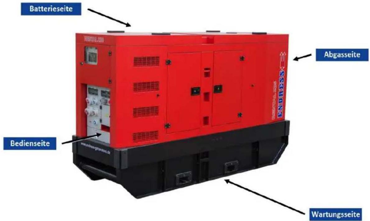
Fig. 6-1 Views of the generator
6.2 Exhaust gas and battery side components
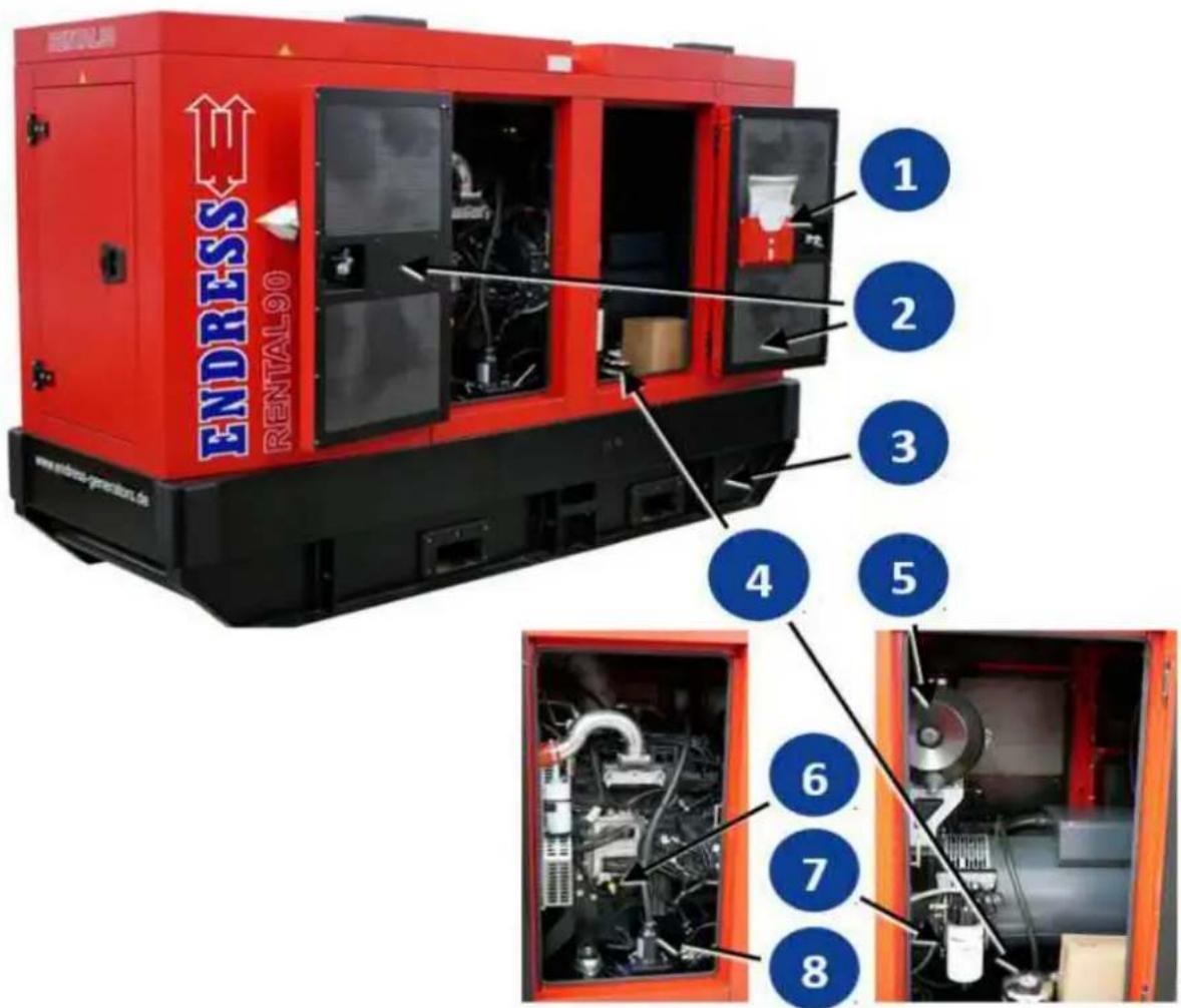
Fig. 6-2 Components on the connecting side
| 1 | Compartment for device documentation Maintenance hatch | |
| 3 | Drain screw for collection pan Tank filling port4 | |
| 5 | Engine air filter Oil dipstick | 6 |
| 7 | Pre-filter | 8 |
6.3 Components on the maintenance side

Fig. 6-3 Components on the maintenance side
| 1 | FPT drive engine Synchronous generator | 2 | |
| 3 | Base frame with tank and collection pan Starter battery | ||
| 5 | Main battery switch Forklift pockets with edge protection | ||
6.4 Components for operating panel and switch box

Fig. 6-4 Components for operating panel and external switch box
| 1 | Control module E-MCS 7.0 Test button for | 320 mA | differential current release |
| 3 | Controls ON/OFF switch Insulation monitoring | ||
| 5 | Main switch Circuit breaker 16 A/4-pin for socket | 66ket | 16(with IT/TN 32A) |
| 7 | Circuit breaker 1-pin RCD (30 mA) for socket 14 | 8 | RCD (residual current circuit breaker)30 mA for sockets 17 |
| 9 | Circuit breaker 63A / 4-pin for socket 16(not on IT/TN) | 10 | EMERGENCY STOP switch |
| 11 | Remote start socket (HARTING) Terminal | stop 5-pin / 63A | |
| 13 | POWERLOCK BOX (optional) Socket 230V1416A* | ||
| 15 | Connection terminal Potential equalization / earthing | 16 | CEE socket 400V 63A 6h red* ORCEE socket 400V / 125A 1h white** |
| 17 | CEE socket 400V / 32A/16A 6h red* Operating hours counter | ||
| 19 | Operating mode selection switch (IT/TN version) | 20 | Horn |
IT/IN version: *active only during on-site operation **active only during with building supply
NOTES
7 Commissioning
The following chapter explains the basic procedure for initial or repeated generator start-ups in "direct supply" mode. Perform the following described steps when you put your generator into operation for the first time or again after transport.

NOTICE!
For start-up and operation of a Generators on building and assembly sites, Deutsche Gesetzliche Unfallversicherung (DGUV) in DGUV Information 203-032, the May 2016 edition, requires observance of special protective measures and behaviour regulations.
Be sure to refer to the following section for a summary of this DGUV information. It supplements the operating manual for this special application.
We also urgently advise observance of relevant DGUV information under comparable operating conditions.
We recommend that you read DGUV Information 203-032 before starting the initial commissioning. When in doubt, consult a qualified electrician.
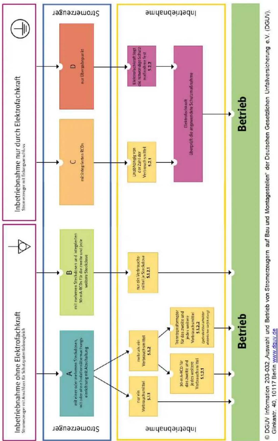
Fig. 7-1 Setting up personal protection measures (source: DGUV)
7.1 Transporting and preparing your generator
Choose the transport vehicle and lifting gear so that the generator can be moved safely at all times according to its total mass (see Chapter 14). The unit's solid base frame allows it to be lifted and transported by a forklift. Alternatively, loading by crane is also possible after the crane eyes have been installed correctly.
Ensure that all of the power generator's maintenance hatches and covers are securely closed.
Conditions
√ The ground at the installation site must be even and be capable of bearing the load.
√ The generator is turned off.
√ The generator has cooled down

! DANGER!
Danger of severe or mortal injuries being incurred from falling loads.
▶ Never stand under or close to a suspended load, also not to provide assistance.
▶ Ensure that there is no person in the area of swivel of the lifting device.
▶ Use all suitable measures to prevent the suspended load from swaying.

NOTICE!
Leaking engine oil and operating fluids can contaminate the soil and groundwater.
▶ Ensure that the generator is transported horizontally and mounted.
▶ Make all efforts, at all costs, to prevent escaping of operating fluids.
▶ Dispose of contaminated soil immediately and according to regulations.
Transporting by lifting forks
- Align the lifting forks (e.g. forklift) with the position of the forklift pockets Fig. 6-3 off.
- Insert the lifting forks as far as possible because of the machine's heavy weight.
- Raise the power generator slowly and evenly.
- Move the power generator slowly into its place of use.
- Lower the device slowly and evenly.
- Remove the lifting forks.
The unit has been transported and positioned at its work site.
Transport by crane
- Screw the included crane lugs onto the top of the power generator (if they are not already mounted).
- To the crane loading lugs, fasten a lifting mechanism approved for the high device weight.
- Secure the lifting mechanism against falling out.
- Raise the power generator slowly and evenly.
- Move the power generator slowly into its place of use.
-
Lower the device slowly and evenly.
-
Unhook the lifting device.
The unit has been transported and positioned at its work site.
7.2 Refuelling your generator
Proceed as follows to the generator.
Conditions √ The generator is turned off.
√ The generator has cooled down.
√ There must be an adequate air supply and air removal.
√ All power consuming equipment must be disconnected or switched off.


DANGER!
Leaking engine oil and fuel can burn or explode.
A risk of suffering severe even deadly burns.
▶ Prevent engine oil or fuel from leaking out.
▶ Never open the tank cover during operation or when it is hot.
▶ Remove leaked operating fluids immediately and appropriately.
▶ Never use an additional starting aid.
▶ Smoking, naked flames and sparks are forbidden.

NOTICE!
Leaking fuel can contaminate soil and groundwater.
▶ Take note of the residual quantity in the tank and its maximum filling capacity.
▶ Always bear in mind that the fuel gauge reacts only after a time delay.
▶ Fill the tank to a maximum of 95%.
▶ Always use a filling aid (e.g. funnel).

NOTICE!
Use of wrong or outdated fuel damages or destroys the engine.
▶ Only use the fuel displayed on the sign (Tab. 3-1).
▶ Observe the possibly enclosed documentation for the fuel release of the engine manufacturer
▶ Observe the shelf life of the fuel according to the supplier.
▶ Observe the engine operating manual.
Refuelling the generator
- Put the Fuel tap in "INTERNAL TANK" position.
- Screw off the tank cover (Fig. 6-2).
- Insert filler aid into the filler neck.
- Fill with fuel slowly and evenly.
- Observe the tank gauge (Fig. 6-2), so as not to overfill the tank.
- Remove the filler nozzle.
- Reinstall the tank cover.
The generator is now refuelled.
7.3 Starting the generator
Power generator start-up in manual control mode (see Chapter 8.1) is described here.
Proceed as follows to start the power generator from the E-MCS 7.0 control module of the operating panel.

Fig. 7-2 Manually starting and stopping the power generator
Conditions
√ The electrical safety has been checked (see Chapter 5).
√ The fuel tank is full enough.
√ The coolant level is adequate (fill with coolant before first start-up; for this, see the engine's operating and maintenance manual).
√ The oil level is adequate (fill with engine oil before initial use, see the engine operating and maintenance manual).
√ There is adequate air supply and air removal.
√ The main battery switch must be in the "ON" position.

DANGER!
Leaking engine oil and fuel can burn or explode.
A risk of suffering severe even deadly burns.
▶ Prevent engine oil or fuel from leaking out.
▶ Never open the tank cover during operation or when it is hot.
▶ Remove leaked operating fluids immediately and appropriately.
▶ Never use an additional starting aid.
▶ Smoking, naked flames and sparks are forbidden.

DANGER!
Starting the engine
Engine exhaust gases contain poisonous and partially invisible gases such as carbon monoxide (CO) and carbon dioxide (CO2).
Risk of death due to poisoning or asphyxiation.
▶ Ensure that there is good ventilation during the whole period of operation.
▶ Only operate the generator in the open.
▶ Never direct the exhaust gases into rooms or pits.
-
Turn the selection switch 1 in position 2 "on-site operation" (IT/IN version only).
-
Turn the controller's switch into the "ON" position.
The control module's display will come on and the controller will run up.
- Wait until the start screen is displayed (see Fig. 8-4).
- Set up "Manual" mode on the display by pressing the mode button (right arrow) once.
- Press the "Start" button once.
The engine will start up after the preheating phase.
The engine has started.
The green control LED shows you whether the Generators is ready.
Familiarize yourself with the complete operating procedure for the E-MCS 7.0 control module before initial commissioning of the power generator, see Chapter 8.1.

NOTICE!
Do not apply load to the generator immediately after a cold start.
▶ Allow the generator engine to warm up for a few minutes before switching on a load when the generator has not been operating for more than eight hours (or for very low external temperatures).
7.4 Low load diesel engine operation
Internal combustion engines normally run most economically and environmentally friendly when they have reached their optimum operating temperature (with a coolant temperature from approx. 80°C). Prolonged operation well below the operating temperature or without a specific minimum load will have a negative effect on the service life. Incomplete combustion processes inside the engine will cause more and more deposits to form within the engine. If this operating state continues for too long or it is not compensated for by regular phases running at full load, this might result in a total engine failure and high repair costs in the worst case.

NOTICE!
Damage to the drive motor or other components in the generator that were caused by low load operation that is contrary to our recommendations (see below) and/or those of the engine manufacturer will void any warranty or liability claims.

NOTICE!
Avoid, as far as possible, short-term operation or operation without a load or with a basic load that is too low. Follow these recommendations if the engine manufacturer does not provide detailed information or he provides different information:
▶ Run your power generator at a minimum of 30% - 40% of the rated output (see Technical Data).
▶ Avoid short-term operations where the engine does not reach its operating temperature.
▶ Run the engine under maximum load for at least one hour at regular intervals (monthly).
▶ Take note of the instructions provided by the engine manufacturer
7.5 Turning off your power generator
Conditions
Switch off your power generator as follows:
√ Any hazards that might be caused by interrupting the power supply have been eliminated.
√ Anyone who might be affected by shutting down the power supply has been informed.
√ The power generator is in manual control mode (see Chapters 7.3 and 8.1).
Switching the generator off
- Press the Fig. 7-2 button once. ③
a) If the button Fig. 7-2 is pressed a second time after Step 1, the engine stops immediately without a cool-down phase. 3(not recommended!).
The engine will go into the cool-down phase ("Cool-down" on the display) and shuts off automatically in about two minutes.
- Use the Fig. 7-2 switch to switch the controls to "0".
The generator is switched off and secured.
7.6 Turn off your generator in the event of an EMERGENCY
Your power generator is equipped with an EMERGENCY STOP switch. In an emergency, it allows you to turn the machine off immediately to prevent further hazards.

CAUTION!
The EMERGENCY-STOP smash button is only to be used in the event of a dangerous situation arising in an emergency.
Risk of injuries if consumers are suddenly switch off.
▶ Always switch off the generator normally as described in Chapter 7.5.
Conditions
It must always be possible to actuate the EMERGENCY STOP switch without any preconditions. Ensure that the EMERGENCY STOP switch is easily accessible at all times.
EMERGENCY STOP 1. Push down or hit the red EMERGENCY STOP button.
The engine will stop.
The horn gives off a continuous warning tone.
The control module locks the power generator against further operation.
The EMERGENCY STOP switch's latching function is blocking the Generators against restart.
The EMERGENCY STOP switch is locked in its actuated state. The generator can only be switched back on again after the hazard has been eliminated and if the EMERGENCY STOP switch is unlocked manually. How to unlock the EMERGENCY STOP switch:
Conditions
√ The hazard or cause of the EMERGENCY STOP process has been eliminated.
√ All of the connected consumers are disconnected or switched off.
Removing the EMERGENCY STOP
- Gently turn the red button on the EMERGENCY STOP switch left or right.
The red button unlocks and springs back into normal position.
The Generators is now ready for operation again and can be restarted, see Chapter 7.3.
7.7 Connection of power consuming equipment


DANGER!
Mortal danger due to an electric shock if live parts are touched.
▶ Never operate the device if it is in a damaged condition.
▶ Never operate the electrical consumers and connecting cable (power consuming equipment) in a damaged condition.
▶ Never feed directly into existing networks that are already connected to a power source (e.g. power supplier, solar plant, etc.).
▶ Never operate the device with wet hands.

DANGER!
There will be no RCD personal protection during operation if the earthing of the Generators is faulty.
Mortal danger from electrocution
The use of an RCD (FI circuit breaker) for personal protection requires proper earthing of the Generators and this must be undertaken by a qualified electrician before the initial commissioning.
The effectiveness of this protective measure should be regularly checked by an electrician.
▶ Check the personal protection according to the check intervals given in Tab. 5-1.
You can connect consumers with Schuko or CEE plugs to the following sockets:
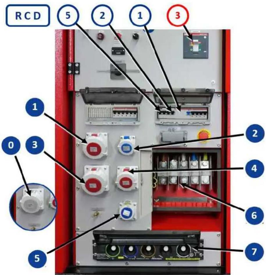
Fig. 7-3 Connecting consumers
| ONLY supplying power to a building RCD | |||
| 0 | CEE socket 400V / 125A / 3~ / 1h 300 mA* | 3 | |
| ONLY on-site operation RCD | |||
| 1 | CEE socket 400V / 32A / 3~ / 6h 30mA | 1 | |
| 2 | CEE socket 230V / 16A / 3~ / 6h 30mA | 2 | |
| 3 | CEE socket 400V / 63A / 3~ / 6h 300 mA* | 3 | |
| 4 | CEE socket 400V / 16A / 3~ / 6h 30mA | 1 | |
| 5 | Schuko attachment sockets 230 V / 16 A / 1~ 30mA | 5 | |
| 6 | Terminal strip 5-pin (ACCESS FOR ELECTRICIANS ONLY) 300 mA* | 3 | |
| 7 | POWERLOCK BOX (option, see Chapter 9.1 ) 300 mA* | 3 | |
| *NO PERSONAL PROTECTION | |||
| Connect a consumer to the power generator as follows: | |
| Conditions | √ The generator is started and brought up to operating temperature (see Chapter 7.3).√ All power consuming equipment is disconnected or switched off.√ All circuit breakers in the fusebox are in “ON” position.√ The control module’s green control LED goes on.The sockets and connected consumers are supplied with voltage. |
| Connecting consumers | 1. Turn the locking ring on the socket’s splash guard anti-clockwise to the stop.2. Fold the splash guard aside with one hand.3. Use your other hand to insert the plug from the consumer to be connected into the socket to the stop.4. Firmly screw the locking ring clockwise on the consumer’s plug.The consumer is connected to the power generator and ready to use. |

NOTICE!
If the control module display shows the home screen (also see Chapter 8.1), you can read the power of the operated consumers from the representation.
7.8 Residual current circuit breaker (RCD)
The residual current circuit breaker (RCD) protects against dangerous body currents in compliance with DIN VDE 0100-551. This version of the generator according to DGUV information 203-032 is classified as a Version C generator for commissioning and operation on building and installation sites and it has the following marking:

It is essential to observe the regulations and safety instructions of the DGUV information 203-032 mentioned in order to achieve protection for all people working in the connected distributor network.
We strongly recommend that you also comply with the requirements of DGUV Information 203-032 for other purposes.

DANGER!
There will be no RCD personal protection during operation if the earthing of the Generators is faulty.
Mortal danger from electrocution
The use of an RCD (FI circuit breaker) for personal protection requires proper earthing of the Generators and this must be undertaken by a qualified electrician before the initial commissioning.
The effectiveness of this protective measure should be regularly checked by an electrician.
▶ Check the personal protection according to the check intervals given in Tab. 5-1.
The operating personnel must press the test button on the residual current protection device (RCD) (1) before every start to check the mechanical release function.

Fig. 7-4 Built-in types of residual current circuit breaker (RCD)
Testing the RCD √ The generator is running
- Move the FI circuit breaker into POS I. ②
- Press the test button.
The switch position 2 indicates the result:
| Symbol Meaning | |
| POS I Circuit breaker does not trip. | |
| POS 0 Circuit breaker trips. | |
The device has been tested in compliance with DIN VDE 0100-551.
- Move the circuit breaker back into POS I to be able to operate consumers from the generator again. 2
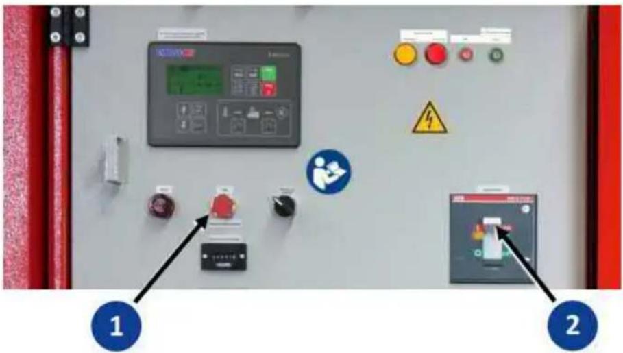
Fig. 7-5 Differential current release
Testing the differential current release
Do as follows to test that the differential current release is responding correctly:
√ The generator is running.
- Move the main switch into POS I. ②
- Press the differential current release test switch.
The circuit breaker position shows the test result. 2
| Symbol Meaning | |
| POS I Circuit breaker does not trip. | |
| POS 0 Circuit breaker trips. | |
The device has been tested in compliance with DIN VDE 0100-551.
- Move the circuit breaker back into POS I to be able to operate consumers from the generator again. 2
In "building supply" mode, the white feed socket (Fig. 7-3 Connecting consumers) is secured against overload and short circuit by the main switch. The integrated differential current release is only for protecting the system. Due to its electrical design, it offers NO PERSONAL PROTECTION! For this, be sure to follow the instructions in Chapter 8.2.
8 The device in-use
8.1 Operating the E-MCS 7.0 control module
We will explain in detail how to operate the power generator from the control module in the following chapter, 7.3 and under various operating conditions. You will also learn how to display and edit various operating parameters and error messages.
The uses different control modes. The control mode that is currently being used is shown in the top line of the display, see Fig. 8-1. Change modes by pressing the buttons on the control panel Fig. 8-2 on the control module.

Fig. 8-1 Control module's display
Control mode A- Controller off
The “” displayed in the top line of the display indicates that the Generators can neither be started manually from the control module nor automatically due to a problem caused by the supply distributor. This mode is reserved for maintenance and configuration work or if starting the Generators must be prevented under all circumstances.

NOTICE!
Automatic grid switching is deactivated in the “A” control mode.
The power generator will not start if the power supply has failed.
▶ Use only the “” control mode for temporary purposes and only if starting the Generators must be prevented.
▶ After you have finished accessing the unit, you must ensure that the control module is back in the “” mode.
Control mode - Manual operation
The manual is indicated by "10" being displayed in the top line of the display, see Fig. 8-1. The power generator can be switched on and off manually and other functions can also be controlled in this mode.

NOTICE!
Automatic grid switching is deactivated in the "MAN" control mode.
The power generator will not start if the power supply has failed.
▶ Only use the manual control mode for temporary purposes or if automatic mains switching is not needed.
▶ After you have finished accessing the unit, you must ensure that the control module is back in the “” mode.
Control mode - Automatic
The Automatic control mode is indicated by “” being displayed in the top line of the display. The generator will start automatically in this mode as soon as the integrated mains monitoring system detects a power grid fault. However, some functions such as resetting the warning tone can still be used.
Controller switched off
If the 7.3 switch is in "0" position, the controls for the Generators are completely shut off. The power generator cannot be started neither automatically nor manually in this mode.
! DANGER!
Dangerous electrical voltage is still present even when the power generator is switched off
Mortal danger from electric shock if live parts are touched.
▶ Access only for electricians in areas marked with an adjacent warning symbol.
▶ Maintenance on the generator is only to be done after an electrician has switched off the power generator and it is completely voltage-free.
8.1.1 Operating panel for control module E-MCS 7.0
Description and function of the operating buttons
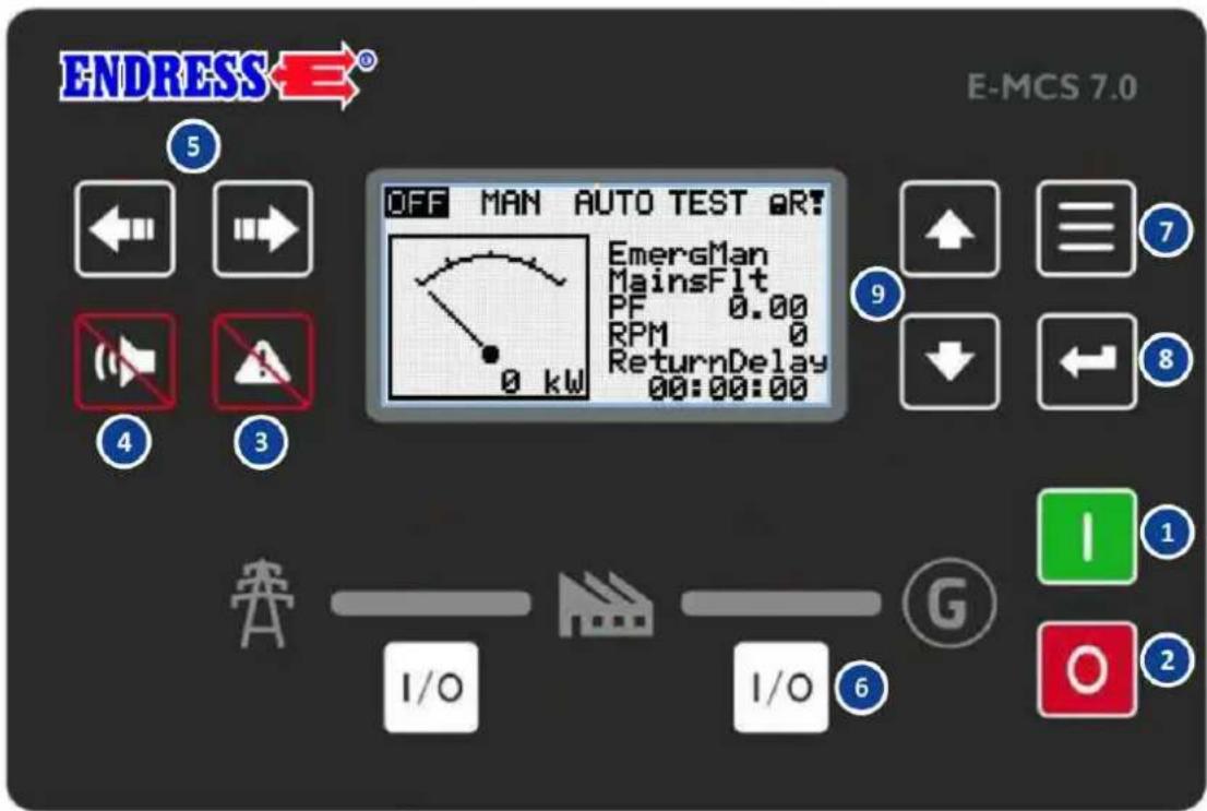
Fig. 8-2 Control module's control panel
| Item Button Description | ||
| 1 |  | START ENGINE Press this button to start the power generator if control mode is selected (also see ) 5 |
| 2 |  | SWITCH OFF ENGINE Press MAN this button once in control mode and the control module will start the power generator's cool-down phase, and it will be switched off afterwards. If this button is pressed for a 2nd time, then the control module will skip the cool-down phase and the power generator will be switched off immediately (NOT RECOMMENDED!). |
| 3 |  | RESETTING A FAULT Press the button to acknowledge an alarm message displayed on the screen and to turn off the horn. Inactive alarms are immediately faded out on the display and the status of the active alarms changes to "acknowledged" so that this will be faded out immediately after the cause is eliminated. |
| 4 |  | RESETTING THE HORN Press this button to deactivate the horn output without acknowledging the alarm. |
| 5 |  | SELECTING A CONTROL MODE Pressthis button to switch between the or ) control modes. The buttons will only be functional if Fig. 8-4 is displayed in the main window on the control screen. If necessary, you should press the 9 button repeatedly until the main window is displayed. |
| 6 |  | SELECTION SWITCH FOR GENERATOR MODE OR POWER GRID MODEPress this button to supply the connected distributor network from the power generator in control mode, or the connected distributor net-work through the public power grid. |
| 7 |  | MENU SELECTIONThis function can only be enabled by service personnel. |
| 8 |  | ENTER BUTTONUse this button to confirm or quit editing a setting. |
| 9 |  | MOVING BETWEEN THE SCREEN PAGESPress these buttons to move between the different windows displayed on the screen. |
Tab. 8-1 Control buttons on the control module

Fig. 8-3 Operating display on the control module
Item Description

GENERATOR STATUS DISPLAY There are two statuses: Unit OK (display is green), and Unit Fault (display is red). The green LED lights up if voltage from the generator is present and the voltage parameters are within the limit values. After the button is pressed (FAULT RESET), it starts to glow continuously (if an alarm is still active) or goes out (if no alarm is still active).

LOAD The green LED lights up if there is voltage present from the generator and the measured parameters lie within the limit values.

GRID STATUS DISPLAY There are two statuses: Grid OK (display is green), and Grid Fault (display is red). The green LED lights up if voltage from the grid is present and the voltage parameters are within the limit values. After the button is pressed ③ (FAULT RESET), it starts to glow continuously (if an alarm is still active) or goes out (if no alarm is still active).
Tab. 8-2 Operating display on the control module
8.1.2 Display window on the control module's screen
The control module screen shows you different Information about operating statuses, measured values, error messages and statistical data is shown in a structured form in the display windows. Press the arrow buttons Fig. 8-2 to move around the different display windows.
You will find a detailed list with all event and error messages in the appendix.
alarm list
If an alarm is triggered, the alarm list will be displayed on the screen and you should select the entry that is preceded by an *. Acknowledge the alarms as follows:
- If there are several entries present ⑨ should use the arrow keys to select the entry that you want.
- Press the button to acknowledge the alarm.
The * character will disappear.
The entry will only disappear after the error has been eliminated.

Fig. 8-4 Sample from control module's display screen
8.2 Select operating mode (II / TN-S)
The following section explains the precise procedure for operating the generator under different operating conditions. Your generator has a change-over device that allows you to use the generator in two different modes:
• Operation for supplying a mobile distribution system
• Building supply for supplying a stationary system
Selection of the right operating mode is specified based on the purpose.
NOTICE!
Press the operating mode selection switch (Fig. 6-4) ONLY when the power generator is not running!
The correct operating mode (building supply or on-site operation) must be selected before you start the generator.
8.2.1 Direct supply mode
The generator is designed for use with one or more electrical consumers (as per VDE 100, Part 551) in "on-site operation". The protective conductor of the ground contact socket assumes the function of the potential equalization line. Current consumption in "on-site operation" mode occurs through several sockets with blue colour identification (230V / 50 Hz / 1\~) or red colour identification (400V / 50 Hz / 3\~), see Fig. 7-3. Use the selection switch Fig. 6-4 to select "on-site operation" mode.

NOTICE!
Insulation monitoring must be always be checked before starting your daily work in "Direct supply" mode.
▶ Always follow the working steps described in Chapter 8.3 BEFORE you connect up consumables or make cable connections to the sockets.
Follow the working steps for starting the generator described in Chapter 7.3.
Follow the work steps for connecting consumers described in Chapter 7.7.
8.2.2 Building supply operating mode
The "building supply" operating mode is used to supply stationary systems such as residential houses or public facilities. The generator serves as the emergency power supply to maintain power if the public power supply fails.
NOTICE!
For further steps it is assumed that the building is equipped with an emergency power supply, which was installed by a specialist company under the supervision of an electrician and that this was implemented in compliance with VDE 0100 Part 551 and VDN.


DANGER!
There is NO PERSONAL PROTECTION on the generator's side when using the power supply socket as no RCD (residual current circuit breaker) is installed!
Mortal danger from electrocution
▶ Installation and commissioning is only to be undertaken by a qualified electrician
▶ Personal protection (RCD) must be ensured on-site.
▶ Check the personal protection according to the check intervals given in Tab. 5-1.
The supply into the stationary system is through a flexible connection line (H07RN-F or comparable) in the supply distributor installed on-site through the CEE power socket (Fig. 7-3 with white colour marking). All other sockets are not usable in this operating mode.
Ensure that the flexible connection line is suitable for the selected operating conditions and power output requirements.
Conditions The following requirements must be met:
√ Generator is ready for operation.
√ The selection switch for the supply distributor is in the "Network" or "0" position.

WARNING!
Danger from machines suddenly starting up.
Risk of severe or even mortal injuries.
▶ You must ensure that all consumers in the stationary system's distribution network are switched off or disconnected from the network BEFORE you switch the supply distributor over to emergency power.
▶ Take note of the instructions in the supply distributor's operating manual.
NOTICE!
Ensure that there is a clockwise rotating field applied to the feed distributor at the sides of the emergency power infeed. The rotational field must be checked by a qualified electrician if there is no appropriate direction of rotation indicator on the supply distributor, (see Fig. 8-5).
Create the power feed connection
Proceed as follows to create a power feed connection between the generator and the on-site installed feed distributor:
- Connect the flexible connection cable to the CEE socket with white colour code Fig. 7-3.
- Connect the flexible connection line with the power socket to the on-site installed feed distributor.
- Use the selection switch to choose the "building supply" operating mode Fig. 6-4.
- Start the generator, see Chapter 7.3.
- Set the selection switch on the supply distributor to "emergency power" position.
The emergency power supply is created.
The stationary system is fed by the generator.

Fig. 8-5 TN system / TT system version example
8.3 Insulation monitoring
"On-site operation" mode is equipped with insulation monitoring with shut-off. The insulation monitoring provides electrical safety to the generator and to all connected consumers and cable connections during continuous operation.
A possible insulation fault is displayed in two stages:
- Yellow warning light with warning tone:
a) There is an insulation fault with transfer resistance lower than 46 kΩ but higher than 23 kΩ in a current circuit of the power generator, the cable network or a connected consumer.
Result: Operation is still possible, and the main line circuit breaker is still on. However, the cause of the insulation fault must be fixed soon. If the insulation fault occurs only in connection with a specific consumer or cable connection, the corresponding part must not continue to be used.
If the fault continues to occur after all consumers have been unplugged, immediately contact service personnel.
- Red warning light with warning tone:
a) There is an insulation fault with transfer resistance lower than 23 kΩ in a current circuit of the power generator, the cable network or a connected consumer.
Result: Operation is no longer possible, and insulation monitoring trips the main line circuit breaker. The power generator cannot be operated again until the cause of the insulation fault is fixed. If the insulation fault occurs only in connection with a specific consumer or cable connection, the corresponding part must not continue to be used.
If the fault continues to occur after all consumers have been unplugged, immediately contact service personnel.

! WARNING!
Change in the hazardous situation when using the insulation monitoring option.
Electric shock hazard if consumers are connected wrong
If you have selected the "insulation monitoring" option, your power generator becomes a Version A device (also see Fig. 3-3).
▶ Always follow the instructions from the DGUV for Version A power generators (see infographic Fig. 7-1 and Chapter 7.7).
NOTICE!
The operating personnel must check the function before every start-up by pressing the insulation monitoring test button (see Chapter 5 Checking the electrical safety as well).
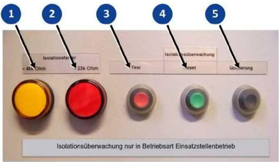
Fig. 8-6 Insulation monitoring
Test the insulation monitoring function as follows:
Conditions √ The generator has started and is running.
- Disconnect all of the consumers from the generator's sockets.
- Make sure all circuit breakers are turned on (switch in POS-I).
- Press the test knob for a few seconds.
The lamps and the position of the line circuit breaker indicate the result of the test. ① ②
| Lamp Result | Meaning | |
| Lights yellow and red | Line circuit breaker jumps to POS 0 | Insulation monitoring is OK |
| stays off Line | circuit breaker remains in POS 1 | Insulation monitoring is defective |
| stays off Line | circuit breaker jumps to POS 0 | Lamp defective |
The insulation monitoring function has been successfully tested.
- Press the button to reset the horn.
- After inspection, the reset button must be pressed and the circuit breaker must be put into POS-1 in order to operate the device again. 4
Insulation monitoring during operation With the following instructions you will learn how your generator detects an insulation fault of a connected consumable during operation and how it protects you.
Conditions √ The generator has started and is running.
√ Line circuit breaker is in POS I.
- Use a socket to connect a consumer to the generator.
The lamp and the position of the line circuit breaker indicate the result of the test:
| Lamp Result | Meaning | |
| No signal lamp goes on | Line circuit breaker remains in POS 1 | No insulation fault detected Consumer has an insulation fault (≤ 23kΩ) |
| YELLOW signal lamp goes on | Line circuit breaker remains in POS 1 | Insulation fault (≤ 46 kΩ > 23 kΩ) |
| YELLOW and RED signal lamps go on | Line circuit breaker jumps to POS 0 | Insulation fault (≤ 23 kΩ) |
If an insulation fault exists and the unit was previously OK when tested without a device connected (see above), the insulation fault has been caused by the device.
- Use its operating switch to switch off the consumable.
- Disconnect the consumer from the generator's socket.
- Press the button to reset the horn.
- Press the reset button to reset the insulation monitoring system.
- Move the line circuit breaker into POS I.
Your generator is ready to use again.

WARNING!
Risk of touching surfaces that are live due to faulty insulation.
Danger of electric shock if a second insulation fault occurs.
The relevant consumable is not to be used any more after an insulation fault has been determined.
▶ Secure the defective consumable effectively against reuse by third parties.
▶ Replace the consumer or have it repaired by a qualified electrician.
8.4 2-way fuel valve
When supplying fuel, you can choose between the internal tank and an external refuelling device. To change refuelling methods, there is a 2-way tap behind the maintenance hatch on the maintenance side of the power generator.
Do as follows to operate the power generator with an external refuelling device:
Conditions
√ An external fuel tank equipped with a refuelling device (see instructions below) is available.
√ The fuel tank is full enough.
√ The power generator's internal tank is full enough.
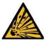

DANGER!
Fire and explosion hazard from leaking fuel
Risk of severe to deadly burns.
▶ Prevent fuel from leaking.
- Keep the refuelling device's fuel cannister firmly closed.
▶ When changing the fuel cannister, stay as far away as possible from the power generator.
Remove unneeded fuel cannisters from the power generator's work area immediately.
▶ Smoking, naked flames and sparks are forbidden.
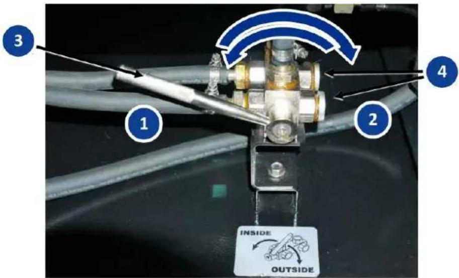
Fig. 8-7 Refuelling device connection
Connect refuelling device
- Remove the stoppers from the hose holes on the base frame.
- Make sure the 2-way tap's lever is in internal tank position ("INSIDE").
- Remove the dummy plugs from the feed and return connections. . 4
-
Guide the ready-made fuel hoses for the refuelling device though the holes and screw them as follows to the connections on the 3-way tap:
a) Connect the fuel feed hose.
b) Connect the fuel return hose. -
Put the lever for the 2-way tap in "OUTSIDE" position.
-
Start the generator (see Chapter 7.3) and wait for the RPM to stabilize.
The refuelling device is attached. The power generator is supplied with fuel through the refuelling device.

NOTICE!
When the lever of the 2-way fuel tap is in "OUTSIDE" position with the engine running, without the refuelling device connected, air can get into the engine's fuel system.
The drive engine shuts off for lack of fuel.
▶ Do not put the 2-way fuel tap into "OUTSIDE" position until the refuelling device is securely connected.
Do as follows to disconnect the refuelling device:
Conditions √ The internal tank is full enough.
Disconnecting the refuelling device
√ The power generator is switched off.
-
Turn the lever of the 2-way fuel tap to "INSIDE" position. The engine is supplied with fuel from its own tank.
-
Remove the fuel hoses of the external refuelling device from the connections. 4.
-
Close the connections with the dummy plugs. 4
-
Insert the stoppers back into the base frame's hose holes.
The refuelling device is disconnected.
8.5 HARTING remote starting device
The optionally installed HARTING® socket allows you to turn your power generator on and off remotely in connection with a suitable external installation (such as a control station).


WARNING!
Beware of machines starting in automatic mode.
Risk of severe injury or death.
▶ Do not make the remote start connection unless the power generator is completely ready to operate and all maintenance covers and hoods are closed.
▶ Only then, start the controls in automatic mode.
▶ Take suitable measures to make nearby operating personnel aware of the automatic operation.

NOTICE!
Important information in the documentation for the additional components.
▶ Always observe the further instructions and handling guidelines in the documentation for the external component or installation.
Setting up the remote start connection
Do as follows to operate the power generator from the remote starting device:

Fig. 8-8 Remote starting device with HARTING® socket
Conditions √ The power generator is ready for operation.
√ The starter battery is properly connected.
√ All consumers are switched off or disconnected from the generator.
1. Firmly press the locking bracket Fig. 8-8 toward the power generator. 2
2. Open the HARTING® socket's safety cap Fig. 8-8 upward.
3. Push the HARTING® plug of the external connection cable onto the HARTING® socket until the stop.
4. Pull the locking bracket Fig. 8-8 toward the HARTING® plug to lock it. 2
The remote starting device is ready to operate.

NOTICE!
Further steps for starting and stopping the power generator are in the operating manual for the external component or installation.

NOTICE!
If the remote starting device is connected, the power generator CANNOT be turned off from the control module (see Chapter 8.1). Use the EMERGENCY STOP switch if an emergency occurs (see Chapter 7.6).
Disconnecting the remote start connection
Do as follows to disconnect the remote start connection remote control after the generator has been switched off:
- Firmly press the locking bracket Fig. 8-8 toward the power generator.
- Pull the HARTING® plug of the external connection cable out of the HARTING® socket.
- Close the HARTING® socket's safety cap Fig. 8-8 downward.
- Pull the locking bracket Fig. 8-8 toward you to lock the safety cap. 2
The remote start connection is disconnected.
9 Optional fittings
9.1 Powerlock-Box
The POWERLOCK BOX allows secure connection of powerful consumers through individual cores with current strength up to 660 A. It therefore has comparable output data to a traditional terminal strip, but it has the advantage of tool-free connection without an electrical expert.
To connect single cores to the POWERLOCK BOX, it must be equipped with the right power connectors.

WARNING!
Hot arcs can occur when connecting or disconnecting under voltage.
Burn or electric shock hazard.
▶ Always de-energize the POWERLOCK BOX before opening or closing the cover.
▶ Always de-energize the POWERLOCK BOX before inserting or removing the plugs.

PE → N → L1 → L2 → L3
Fig. 9-1 POWERLOCK BOX
Do as follows to connect consumers through the POWERLOCK BOX to the power generator:
Conditions
√ The circuit breaker for the POWERLOCK BOX (see power generator operating manual) is in "0" or "OFF" position.
√ The consumer to be connected is shut off.
Step by step
-
Turn the locks left and right of the cover flap using the included square wrench in the direction of the arrow. 0
-
Open the cover flap of the POWERLOCK BOX.
-
FIRST connect the plug of the PE conductor (protective earth) to the left plug connection.
-
Insert the POWERLOCK plug connector to the connection into the provided bushing in the POWERLOCK BOX, and lock it with a 45° clockwise turn.
-
Proceed in exactly the same way in the specified sequence with the other POWERLOCK plug connectors.
-
Then secure all locks by turning the lock with the square wrench anti-clockwise to the stop. 6
-
Switch the circuit breaker for the POWERLOCK BOX to position "1" or "ON". The consumer is securely connected and can be operated.
NOTICE!

If one of the plug connections or the lock cannot be locked, one of the previous plug connections has not been locked properly. 6
▶ Turn each plug connector to the stop before inserting the next one.
▶ Never turn the main switch back on before all plug connectors and the lock have been properly locked. 6
To undo the POWERLOCK connection, perform the steps in reverse order. Before that, be sure to turn off the affected consumer and set the circuit breaker for the POWERLOCK BOX to "0" or "OFF" position.
9.2 Dummy load
The power generator has a dummy load with an output adapted to the drive engine. This is electrical load resistance that automatically creates a base load as soon as the engine is running below the specified load limit.
During extended operation at low load, deposits form in the engine that, with time, cause increased wear and possibly severe engine damage. Automatic switch-on of the dummy load increases the burn temperature enough that the deposits are completely removed. The control electronics turn the dummy load off automatically as soon as a consumer with adequate power is connected to the power generator. This ensures that the generator's full power is available at all times.
The dummy load is controlled automatically and requires no intervention by operating personnel. You can tell the dummy load is active when the control module display shows power output when no or only minor consumers are turned on (in the example below, 3 kW).

Fig. 9-2 Display with dummy load operating
9.3 External battery charging
The additional option for external battery charging ensures that the drive engine's starter battery is permanently charged. This increases safety of use by enabling trouble-free engine start-up (if the starter battery is in perfect condition). With this option, your Generators has an integrated automatically operated battery charger that is supplied with a 230 V AC connection.

WARNING!
Escaping corrosive acid fumes or sulphuric acid during and after the charging process. A risk of suffering severe or even deadly burns.
▶ Only work with acid-resistant protective equipment.
▶ Clean surfaces covered in acid immediately using adequate amounts of water.
▶ Only charge the starter battery in a well ventilated environment.

! WARNING!
During the charging process, never undo the cable connections to the starter battery. Before you start the power generator, you must end the charging process and let the starter battery rest with good ventilation for about 30 minutes.
Do as follows to charge your Generators's starter battery through external battery charging:
Conditions

Fig. 9-3 230 V feed plug for battery charger
√ The Generators is ready to operate.
√ The starter battery is connected as specified to the drive engine's current circuit.
- Turn the locking ring on the feed plug clockwise to the stop to remove the plug's cover.
- Connect the feed plug using a commercially available Schuko connection cable to an existing 230 V AC network.
The The battery charger turns on automatically.
The starter battery is charged.

NOTICE!
The battery charger automatically transitions to charge retention when the set end-of-discharge voltage is reached. When the charging system is intact, overcharging is not possible, and the charge connection to the Generators can remain until next use.
10 Maintenance
Generators maintenance is described in this section. It may only be performed by qualified specialist personnel.
Maintenance and repair which is neither described in this operating manual nor in the possibly also delivered operating and maintenance instructions may only be undertaken by authorized service personnel from the manufacturer.
10.1 Maintenance plan
Maintenance on the generator mainly involves work on the drive engine and some work on the other equipment.

NOTICE!
Always follow the accompanying operating and maintenance manual provided by the engine manufacturer doing maintenance on the drive engine.
An overview of the schedule and scope of necessary maintenance can be found in the maintenance plan in the engine manufacturer's operating and maintenance manual.
10.2 Maintenance work
Only authorised personnel are allowed to carry out maintenance tasks. Carry out all of the maintenance work listed in the maintenance plan according to the instructions given in the accompanying operating and maintenance instructions provided by the engine manufacturer. This operating manual merely describes the instructions that differ from or go beyond those instructions.

DANGER!
Mortal danger from unintentional generator start up.
Danger of burns and being caught by rotating parts.
Before accessing the generator you must switch it off and secure it so that unintentional starting of the machine is prevented under all circumstances. (see Chapter 8.1 as well).

CAUTION!
Certain surfaces on the device can get very hot whilst it is running.
Risk of burns
▶ Never touch any engine parts (in particular the exhaust system) for a few minutes after ceasing operation.
▶ Always leave hot engine parts to cool down before touching them.
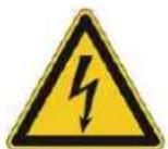
NOTICE!
Also always read about the checking and maintenance work which concerns the electrical safety of the generators in the chapter "Checking the electrical safety".
10.3 Starter battery
10.3.1 Replacing the battery


WARNING!
There is a risk of explosion and fire in the case of inappropriate handling and spark development when working with the battery.
Danger from spraying sulphuric acid. Danger of suffering severe even deadly burns and chemical burns. Danger of being blinded.
▶ Never lay electrically conductive parts on the starter battery.
▶ Flames, sparks, an open light and smoking are prohibited.
▶ Avoid sparks when handling cables and electrical devices, as well as electrostatic discharge.
▶ Avoid short-circuits.
▶ Wear acid-resistant protective clothing.

1
2

Fig. 10-1 Starter battery (illustration similar)
Conditions

Change the starter battery as follows:
√ Power generator is switched off (7.3 switch 1 is in the "OFF" position)
√ Battery disconnection switch is in "OFF" position ( ) 5
√ You are wearing personal safety equipment.
√ Feed plug disconnected from the integrated battery charger.

-
Interrupt the battery circuit from the main switch (position Fig. 10-1 7 1)
-
Pull off the terminal protection cap (if present) from the battery's negative terminal and the negative cable Fig. 10-1 must always be the FIRST cable to be disconnected from the battery. 3
-
Pull off the terminal protection cap (if present) from the battery's positive terminal and remove the positive cable Fig. 10-1 from the battery LAST.
-
Undo both fastening nuts and remove the battery's holding bracket. ⑥ Fig. 10-1 ⑤
- Remove the battery from the power generator. The starter battery is now removed.
- Prepare a new starter battery (follow the battery manufacturer's instructions).
- Place the starter battery in the battery compartment.
- Use the retaining bracket to secure the starter battery in placeFig. 10-1 . 5
- FIRST attach the positive cable Fig. 10-1 to the positive pole of the battery and then pull the red terminal protection cap over the terminal, if necessary. 4
- LAST attach the negative cable Fig. 10-1 to the negative terminal of the battery and then pull the terminal protection cap over the terminal, if necessary.3
- Turn the battery disconnection switch 7 to ON (position Fig. 10-1 2)
The starter battery has been replaced. The generator can now be started.
10.4 Engine oil
The drive motor for your generator, like every internal combustion engine, requires the required engine oil for cooling and inner cooling. It is also very important to use the correct engine oil, both for refilling and when changing the oil, and to adhere the stipulated maintenance intervals. Refer to the accompanying operating and maintenance instructions provided by the engine manufacturer for all necessary information.
10.4.1 Changing the engine oil
In contrast to the operating and maintenance manual for the engine, your power generator has a built in suction pump for engine oil. All engine components important for changing engine oil and oil filters can be reached through the large maintenance hatches on the connection and maintenance side, see Fig. 6-2 and Fig. 6-3.

NOTICE!
Leaking engine oil contaminates the soil and groundwater.
▶ Use a suitable oil catching receptacle.
▶ Old oil is a special waste and may only be disposed of over suitably qualified collection points.


CAUTION!
The engine and operating equipment on the generator can get very hot while running.
Risk of burns
▶ Never touch any engine parts (in particular the exhaust system) for a few minutes after ceasing operation.
▶ Allow the engine to cool off for at least five minutes before changing or checking the engine oil.
To suction out used oil, you also need an oil-resistant hose whose diameter corresponds to the pump opening (see - ) a suitable oil collection pan (not included with delivery). Below, only the procedures that differ from the engine operating manual are explained. 2


Fig. 10-2 Manual oil scavenger pump
Conditions
Ensure that the following prerequisites are met before you change the engine oil:
√ The generator is turned off.
√ When it is still hot: Wait until the engine oil has cooled down to approx. 30° C – 50° C.
√ Let the cold engine appropriately warm up.
Do as follows to suction up the used oil:
- Open the shut-off valve by pressing the valve anti-clockwise and downward.
- Guide the hose into a suitable oil collection container.
- Move the suction pump's hand grip Fig. 10-2 up and down until no more used oil comes from the engine.
- Move the hand grip Fig. 10-2 to the bottom position.
The engine's used oil has been suctioned out.

NOTICE!
The other procedures for changing the engine oil correspond with the details given in the engine's operating and maintenance instructions. Take note of the other maintenance and disposal of operating equipment instructions that can be found there.
10.5 Checking the coolant
We have filled your power generator's cooling circuit with premium coolant that ensures long-term material compatibility, and protection from corrosion and frost. The specification G12+ additive is free of nitrite, amine, phosphate and silicate and is mixed to ensure frost protection to at least a -25°C ambient temperature. So as not to impair the protective effect, use only a maximum 50% mixture for refilling.
NOTICE!
Follow the engine's operating and maintenance manual for all work on the cooling system.
In deviation from this, follow these instructions:
▶ Check the coolant level only from the surge tank (Fig. Fig. 10-3) near the radiator. The fluid level should always be between the Maximum and Minimum marks.
▶ If the tank is empty, the cooling system must be ventilated!

CAUTION!
Hot surfaces and hot, pressurized fluid. Burn hazard.
▶ Never open the radiator cap when the engine is running or is hot.
▶ Before opening the radiator cap, let the engine cool down.
▶ Open the radiator cap slowly, so that the overpressure in the tank can dissipate slowly.

Fig. 10-3 Checking the coolant
11 Storage
It is important to store the device at a suitable storage location as soon as your generator is no longer being used.
- The storage location must be roofed and must not be subjected to standing water, aggressive vapours or soiling as well as major accumulation of dust.
- Protect your device with a cover made out of breathable material.
- Ensure that the storage temperature and air humidity lie within the specified limits (see Technical data).

NOTICE!
Due to the limited shelf life of the different operating fluids, it is important for decommissioning for more than one month that additional measures for storage are taken. While doing this observe the instructions given in the attached operating and maintenance instructions from the engine manufacturer.
12 Disposal

Your device, which is an electrical or electronic device, is subject to European Directive 2012/19/EU ("WEEE directive") which is implemented in Germany in national law through the decree regulating the use of dangerous substances in electrical and electronic equipment (ElektroStoffV). This regulates disposal and use of recycling waste electrical equipment. The adjacent icon with a crossed-out wastebasket on your device states that it must not be disposed of in the household waste at the end of its service life.
As a private end-user (a so-called b2c customer) there are free collecting points (recycling centre) near you for electrical equipment as well as possible also other collection points available for reuse of devices. The addresses can be obtained from your city or communal authority. In as far as the old electrical and electronic equipment contains personal data, you are responsible yourself for its deletion before giving it back.
Pure b2b devices (devices which, for appropriate use, or exclusively are only used the commercial area) must not be disposed of over public collecting points in Germany and further EU countries. Speak to your authorised ENDRESS generator dealer about handing back your recycling waste electrical equipment. The dealer is also your point of contact for any differing regulations on the respective country of deployment. There are also possible agreements in the purchase contract to observe.
Please observe the pertinent environmental protection regulations when disposing of the old oil. We recommend bringing the oil in a closed container to an old oil collection centre for disposal. Never put used engine oil in the domestic waste. Storage or introduction of old oil into nature is associated with very high fines.
An inappropriately disposed of battery can greatly damage the environment. Give back your old battery directly free of charge to your dealer when purchasing a new one.
Always observe the valid local regulations and laws concerning correct disposal of all old parts and operating materials. Please contact your ENDRESS service partner for a replacement.
13 Troubleshooting
The following table is an aid for you to use in a case where faults arise during use. Based on experience a number of malfunctions can already be removed by operating personnel or the possible causes limited. In all other cases contact your service partner as described in the table. The same applies for faults which are not listed in the table.
If a fault cannot be rectified using the measures described here, you must shut down your Generators and secure it against further use. Contact your service partner and give him an explanation, not only of the symptoms but also the possible causes which you can already exclude based upon the table. The fault can often be identified over the telephone or through a written exchange with our specialists.

NOTICE!
The following table does not make any claims to completeness and does not mention any faults which can be caused by operating error.
▶ In order to avoid operating errors, please exactly follow the instructions in the existing and delivered documentation.
▶ See the event and error lists in the Appendix.
| Malfunction Possible cause Correction | ||
| The engine turns but does not start (electrical start). | The controller is being operated incorrectly. | Look at the operating instructions. |
| Maintenance of the engine was inadequate. | Look at the engine maintenance instructions. | |
| The oil level monitor actuates. Check oil level and refill if necessary. | ||
| Too little fuel in the tank. Refuel | ||
| The fuel filter is clogged. Replace the fuel filter. | ||
| Bad fuel in the tank. Replace the fuel, change the fuel filter and clean out the fuel tank if necessary | ||
| The EMERGENCY-STOP button is still locked in place | Unlock the EMERGENCY-STOP button. | |
| The engine turns but does not start (manual start). | The battery connecting cables are un-clamped. | Clamp or screw on the battery connecting cables. |
| Starter battery is discharged | Recharge the starter battery | |
| The engine starts briefly and then shuts down. | Too little fuel in the tank. Refuel: | |
| Tank ventilation is blocked. | Contact your service partner. | |
| The oil level is too low. | Add oil. | |
| The fuel filter is clogged. Replace the fuel filter. | ||
| Malfunction Possible cause | Correction | |
| The engine does not rotate | The starter battery is discharged or defective (only for electrical starting) | Clean the battery poles, check teh starter battery and recharge or replace, check the recharging circuit |
| Starter defective Replace the starter | ||
| Engine is mechanically blocked Contact your service partner | ||
| No or insufficient voltage available during idling without a load. | The rotational speed of the engine was adjusted afterwards. | Contact your service partner. |
| The electronic controller has been altered. | Contact your service partner. | |
| The electronic controller is defective. Contact your service partner. | ||
| Strong voltage fluctuations occur. | The engine runs irregularly. Contact your service partner. | |
| Speed controller working erratically or insufficiently. | Contact your service partner. | |
| The engine smokes. | Too much oil in the engine. Drain off an excess oil. | |
| Paper element of the air filter is dirty or oil-soaked. | Clean paper element or replace if necessary. | |
| Foam element of the air filter is dirty or dry. | Clean foam element and if necessary moisten. | |
| The power output remains significantly below the nominal output | Operation under extreme climatic conditions | Adapt the usage for the climatic conditions or terminate it |
| The generator has been poorly serviced | Perform maintenance work | |
| The generator has reached its wear limit. | Contact your service partner | |
| Generator is not running smoothly. | The generator is loaded beyond its nominal output load. | Reduce power draw. |
| The oil pressure is too low. | Insufficient engine oil in the engine. Refill with engine oil. | |
| Generator does not start automatically. | Remote start connection is faulty or connection has not been made | Remake the remote start connection |
Tab. 13-1 Troubleshooting
Please contact our customer service for further fault diagnosis as well as procurement of original spare parts and wear parts at
Customer service: Tel. +49 7123 973744
Email: service@endress-stromerzeuger.de
Have the item and serial number of your device ready for identification. You will find these details on the type plate (see Fig. 3-1).
14 Technical data
You can find the relevant technical data for your generator in the following table.
| Name Value Unit | ||||
| ESE 67 IW/RS ESE 90 IW/RS ESE 110 IW/RS | ||||
| Continuous power output [PRP] 3~1) | 60 / 48 80 / 64 110 / 88 [kVA / kW] | |||
| Maximum output [LTP] 3~1) | 66 / 52.8 88 / 70.4 6.25 / 5 [kVA / kW] | |||
| Nominal output factor ~3 / 1~ | 0.8 | [cosφ] | ||
| Nominal frequency | 50 | [Hz] | ||
| Nominal speed | 1,500 | [min-1] | ||
| Nominal voltage 3~ / 1~ | 400 / 230 | [V] | ||
| Nominal current [PRP] 3~ / 1~ | 86.6 | 115.5 | 144.3 | [A] |
| Empty weight (approx.) | 1,790 | 1,890 | 2,000 | [kg] |
| EngineOil quantity (including oil filter) | 12.8 | [l] | ||
| Internal tank content | 430 | [l] | ||
| Fuel consumption (at a 75% load)2) | 13.0 | 15.4 | 18.5 | [l/h] |
| Running time (at 75% load) approx.2) | 33.1 | 27.9 | 23.2 | [h] |
| Length | 2,900 | [mm] | ||
| Width | 1,090 | [mm] | ||
| Height | 1,925 | [mm] | ||
| Noise pressure level at the workplace LpA3) | 83 | 86 | 85 | [db (A)] |
| Sound pressure level at a distance of 7m LpA4) | 66 | 69 | 69 | [db (A)] |
| Sound power level LWA3) | 91 | 94 | 94 | [db (A)] |
| Protection Class for the generator | IP23 | IP23 | IP23 | |
| 1) Measured under standard reference conditions | ||||
| 2) Average value; deviations might occur in specific cases, and are therefore non-binding | ||||
| 3) Measured at a distance of 1 m and a height of 1.6 m in accordance with ISO 3744 (Part 10) | ||||
| 4) Measured in accordance with ISO 3744 (Part 10) | ||||
Tab. 14-1 Power generator technical data
The information given in the table applies to the following operating conditions (standard reference conditions):
standard reference conditions
| Name Value Unit | ||
| Set-up height above sea level 100 [m] | ||
| Ambient temperature 25 [°C] | ||
| Relative Air humidity 30 [%] |
The usable power output can deviate from the nominal values depending on the actual operating conditions. The following table provides guide points:
Power reduction
| Reference value Power output | reduction | for each additional |
| Set-up height above sea level 1 % 100 m | ||
| Ambient temperature 4 % | 10°C |
The following table shows you the applicable Operating conditions for running the generator:
ambient conditions
| Name Value Unit | ||
| Set-up height above sea level | max. 2,000 | [m] |
| Ambient temperature | -20 to +40 | [°C] |
| Relative air humidity | max. 95, non-condensing | [%] |
| Tilt angle | max. 20 [°] |
15 Replacement parts
Maintenance and replacement parts can be obtained quickly and easily from your responsible ENDRESS service partner or ENDRESS dealer. You can alternatively obtain support from our central customer service
by telephone: +49 (0) 71239737-44
by email: service@endress-stromerzeuger.de
Have the item and serial number of your device ready for identification.
As a registered user you can obtain rapid and uncomplicated access to a range of services over our home page to obtain suitable original spare parts for maintenance and repair work. Using your internet browser please go to
https://endressparts.com
and click on the area "Documentation and replacement parts".

ambient conditions 74
Ambient temperature 74
B
Base frame 29
Battery charger 63
Brief operating manual 15
C
Change the fuel source 56
Charge retention 62
Control mode 46
AUTO 47
MANUAL 46
OFF 46
switching 48
control module 46
Customer service 75
D
DIN ISO 3864 7
display windows 49
Drive engine 29
E
earthing 10 25 25 30
Electrical safety 25
EMERGENCY STOP switch 15 30 38
evaluated 18
Exhaust gases 20 37
F
Fuel consumption 73
Fuel quality 14
Fuel tap 35
Fuelling 35
H
HARTING socket 58
Home page 75
|
Imprint 2
Included with delivery 12
L
label 13 13
Low-load operation 61
M
Main battery switch 29
Maintenance hatch 28
misuses 11
0
Oil dipstick 28
Oil quantity 73
operating manual 7
Operating personnel 18 23
P
Potential equalization 25 30
power connectors 60
Power reduction 74
Prohibition signs 14
R
Refuelling device 56
Resetting an error message 48
s
safety instructions 16
Safety symbols 16
Setting up height 74
Sound power level 73
standard reference conditions 74
Standards
DIN EN ISO 12100 18
DIN EN ISO 8528-13 18
DIN VDE 82079-1 6
ISO 3864 18
ISO 7010 16
standards
DIN EN 60204 18
Starter battery 29
Starting 36
Switching off 38
T
the power supply companies 11
Tilt angle 74
Type plate 14
U
under the operator's obligations 26
W
Warning notices 18
WEEE directive 70
ENDRESS
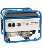
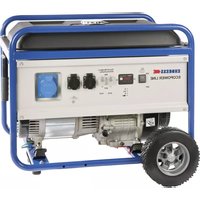
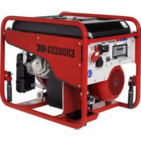
- COPYRIGHT
- NOTES ON PRINTING
- TABLE OF CONTENTS
- 1 DIRECTORIES ....5
- 2 ABOUT THIS MANUAL 6
- 3 PRODUCT IDENTIFICATION 9
- 4 FOR YOUR SAFETY....16
- 5 CHECKING THE ELECTRICAL SAFETY .....25
- 6 DESCRIPTION OF THE DEVICE 27
- 7 COMMISSIONING ....32
- 8 THE DEVICE IN-USE....46
- 9 OPTIONAL FITTINGS....60
- 10 MAINTENANCE....64
- 11 STORAGE 69
- 12 DISPOSAL 70
- 13 TROUBLESHOOTING....71
- 14 TECHNICAL DATA 73
- 15 REPLACEMENT PARTS....75
- 1 DIRECTORIES
- 1.1 LIST OF ILLUSTRATIONS
- 1.2 LIST OF TABLES
- 2 ABOUT THIS MANUAL
- 2.1 CONSTITUENT PARTS OF THE DOCUMENTATION
- NOTICE
- 2.2 USING THIS OPERATING MANUAL
- SIGNS WARNING ABOUT DANGERS TO LIFE AND LIMB
- EXAMPLES
- DANGER
- ELECTRICAL VOLTAGE
- SAFETY SYMBOLS
- NOTICES ON AVOIDANCE OF DAMAGE TO THE DEVICE
- USE OF WRONG OR OUTDATED FUEL DAMAGES OR DESTROYS THE ENGINE
- SYMBOLS AND FORMATINGS IN THE TEXT
- EXAMPLE
- 3 PRODUCT IDENTIFICATION
- 3.1 WELCOME TO ENDRESS
- 3.2 YOUR PRODUCT
- CUSTOMER SERVICE
- TYPE PLATE
- 3.2.1 A DEVICE DESCRIPTION AND INTENDED USE
- 3.2.2 FORESEEABLE MISUSE
- 3.3 SCOPE OF DELIVERY OF YOUR GENERATOR
- 3.4 LABELS ON THE GENERATOR
- 4 FOR YOUR SAFETY
- 4.1 SAFETY SYMBOLS
- WARNING OF A GENERAL HAZARD
- WARNING OF A DANGEROUS ELECTRICAL VOLTAGE
- WARNING OF POTENTIALLY EXPLOSIVE MATERIALS
- WARNING OF TOXIC SUBSTANCES
- WARNING OF CORROSIVE SUBSTANCES
- WARNING OF ENVIRONMENTALLY DAMAGING SUBSTANCES
- WARNING OF HOT SURFACES
- WARNING OF A SUSPENDED LOAD
- WARNING OF AUTOMATICALLY STARTING MACHINES
- 4.2 GENERAL SAFETY INSTRUCTIONS
- 4.3 RESIDUAL RISKS
- WARNING
- CAUTION
- EXCESSIVE HEAT OR MOISTURE CAN DESTROY THE DEVICE
- 4.4 AUTHORISED OPERATING PERSONNEL – QUALIFICATIONS AND OBLIGATIONS
- 4.5 DANGER ZONES AND WORK AREAS
- 5 CHECKING THE ELECTRICAL SAFETY
- ON-SITE OPERATION
- EARTHING
- SUPPLYING POWER TO A BUILDING
- 6 DESCRIPTION OF THE DEVICE
- 6.1 VIEWS
- 6.3 COMPONENTS ON THE MAINTENANCE SIDE
- NOTES
- 7 COMMISSIONING
- 7.1 TRANSPORTING AND PREPARING YOUR GENERATOR
- CONDITIONS
- DANGER OF SEVERE OR MORTAL INJURIES BEING INCURRED FROM FALLING LOADS
- LEAKING ENGINE OIL AND OPERATING FLUIDS CAN CONTAMINATE THE SOIL AND GROUNDWATER
- TRANSPORTING BY LIFTING FORKS
- TRANSPORT BY CRANE
- 7.2 REFUELLING YOUR GENERATOR
- LEAKING ENGINE OIL AND FUEL CAN BURN OR EXPLODE
- LEAKING FUEL CAN CONTAMINATE SOIL AND GROUNDWATER
- REFUELLING THE GENERATOR
- 7.3 STARTING THE GENERATOR
- STARTING THE ENGINE
- 7.4 LOW LOAD DIESEL ENGINE OPERATION
- 7.5 TURNING OFF YOUR POWER GENERATOR
- SWITCH OFF YOUR POWER GENERATOR AS FOLLOWS
- SWITCHING THE GENERATOR OFF
- 7.6 TURN OFF YOUR GENERATOR IN THE EVENT OF AN EMERGENCY
- REMOVING THE EMERGENCY STOP
- 7.7 CONNECTION OF POWER CONSUMING EQUIPMENT
- MORTAL DANGER DUE TO AN ELECTRIC SHOCK IF LIVE PARTS ARE TOUCHED
- THERE WILL BE NO RCD PERSONAL PROTECTION DURING OPERATION IF THE EARTHING OF THE GENERATORS IS FAULTY
- 7.8 RESIDUAL CURRENT CIRCUIT BREAKER (RCD)
- 8 THE DEVICE IN-USE
- 8.1 OPERATING THE E-MCS 7.0 CONTROL MODULE
- CONTROL MODE A- CONTROLLER OFF
- AUTOMATIC GRID SWITCHING IS DEACTIVATED IN THE “A” CONTROL MODE
- CONTROL MODE - MANUAL OPERATION
- AUTOMATIC GRID SWITCHING IS DEACTIVATED IN THE "MAN" CONTROL MODE
- CONTROL MODE - AUTOMATIC
- CONTROLLER SWITCHED OFF
- DANGEROUS ELECTRICAL VOLTAGE IS STILL PRESENT EVEN WHEN THE POWER GENERATOR IS SWITCHED OFF
- 8.1.1 OPERATING PANEL FOR CONTROL MODULE E-MCS 7.0
- ITEM DESCRIPTION
- 8.1.2 DISPLAY WINDOW ON THE CONTROL MODULE'S SCREEN
- ALARM LIST
- 8.2 SELECT OPERATING MODE (II / TN-S)
- 8.2.1 DIRECT SUPPLY MODE
- 8.2.2 BUILDING SUPPLY OPERATING MODE
- DANGER FROM MACHINES SUDDENLY STARTING UP
- CREATE THE POWER FEED CONNECTION
- 8.3 INSULATION MONITORING
- RISK OF TOUCHING SURFACES THAT ARE LIVE DUE TO FAULTY INSULATION
- 8.4 2-WAY FUEL VALVE
- DO AS FOLLOWS TO OPERATE THE POWER GENERATOR WITH AN EXTERNAL REFUELLING DEVICE
- FIRE AND EXPLOSION HAZARD FROM LEAKING FUEL
- CONNECT REFUELLING DEVICE
- DO AS FOLLOWS TO DISCONNECT THE REFUELLING DEVICE
- 8.5 HARTING REMOTE STARTING DEVICE
- 9 OPTIONAL FITTINGS
- 9.1 POWERLOCK-BOX
- STEP BY STEP
- 9.2 DUMMY LOAD
- 9.3 EXTERNAL BATTERY CHARGING
- 10 MAINTENANCE
- 10.1 MAINTENANCE PLAN
- 10.2 MAINTENANCE WORK
- 10.3 STARTER BATTERY
- 10.3.1 REPLACING THE BATTERY
- 10.4 ENGINE OIL
- 10.4.1 CHANGING THE ENGINE OIL
- 10.5 CHECKING THE COOLANT
- 11 STORAGE
- 12 DISPOSAL
- 13 TROUBLESHOOTING
- 14 TECHNICAL DATA
- 15 REPLACEMENT PARTS
- B
- C
- D
- E
- F
- H
- L
- M
- 0
- P
- R
- S
- T
- U
- W
- ENDRESS
Brand : Endress
Model : ESE 110 IW/RS
Category : Generator