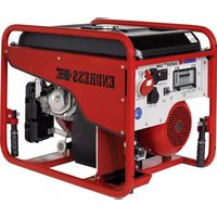
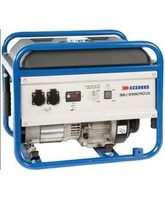
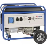
ESE 606 DHG-GT DUPLEX - Generator Endress - Free user manual and instructions
Find the device manual for free ESE 606 DHG-GT DUPLEX Endress in PDF.


| Product Type | Generator |
| Brand | Endress |
| Model | ESE 606 DHG-GT DUPLEX |
| Power Output (Continuous) | 5.5 kW |
| Power Output (Peak) | 6.0 kW |
| Fuel Type | Gasoline / LPG (Dual Fuel) |
| Engine | 4-Stroke, OHV, Air-Cooled |
| Starting System | Electric Start with Recoil Backup |
| Voltage | 230 V (Single Phase) |
| Frequency | 50 Hz |
| Fuel Tank Capacity | 25 L |
| Runtime at 50% Load | 8 hours |
| Noise Level | 68 dB(A) at 7 m |
| Weight | 85 kg |
| Dimensions (L x W x H) | 700 x 550 x 600 mm |
| Output Sockets | 2 x 230V 16A, 1 x 12V DC |
| Protection Features | Overload, Low Oil Shutdown, AVR |
| Fuel Gauge | Yes |
| Wheel Kit | Included |
| Warranty | 2 Years |
Frequently Asked Questions - ESE 606 DHG-GT DUPLEX Endress
User questions about ESE 606 DHG-GT DUPLEX Endress
0 question about this device. Answer the ones you know or ask your own.
Ask a new question about this device
Download the instructions for your Generator in PDF format for free! Find your manual ESE 606 DHG-GT DUPLEX - Endress and take your electronic device back in hand. On this page are published all the documents necessary for the use of your device. ESE 606 DHG-GT DUPLEX by Endress.
USER MANUAL ESE 606 DHG-GT DUPLEX Endress
Publisher ENDRESS
Publication date / Version August 2017 / i04
This documentation and parts thereof are subject to copyright. Any use or modification beyond the restrictions of the Copyright Act is forbidden and subject to penalty without the consent of ENDRESS Elektrogerätebau GmbH.
This applies in particular to copies, translations, microfilming, as well as storage and processing in electronic systems.

Caution!
Important notes on commissioning and operation of the construction and assembly locations.
For this operation special protective measures and rules of behaviour for commissioning must be observed according to the DGUV Information 203-032 Mai 2016 Edition.
The following pages 3 and 4, notes on the DGUV Information 203-032, supplement the operating manual for this special application.
One is recommended to read the DGUV Information 203-032 before performing the first commissioning. In cases of doubt consult a qualified electrician.
Operation of the generator on construction and assembly locations according to DGUV Information 203-032(BGI867).
The following notes should be observed:
Protective measures and rules of behaviour
- The operating instructions from the manufacturer and the accident prevention regulations must be observed and followed.
- Only instructed persons may work with electrical equipment.
- If mobile generators of type A are only operated with one consumer, no further protective measures needed to be taken.
- If mobile generators of type A are operated with many consumer, additional protective measures needed to be taken:
- residual current protection devices (RCDs) with a rated differential current not greater than 30 mA (0.03 A) for the second and every additional consumer.
or
- a separating transformer for the second and every additional consumer for increased danger through having a conductive environment with limited freedom of movement.
- one may not use a PRCD-S here as a residual current protection device since it cannot be switched on.
- for generators with an insulation monitoring device (IMD) the same requirements apply.
- Only rubber-insulated flexible cables of the type H07RN-F or H07BQ-F may be used on construction and assembly locations.
- Electrical equipment must be spray water protected and meet the regulations for rough operation
The generators of type A are marked as follows.
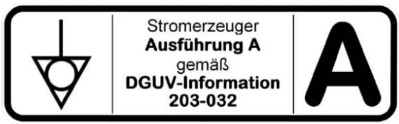
The generators of type C (with integral RCDs) and their designation, see Chapter 5.1.
Also observe the important information for connection of consumers on the supplementary sheet "Important note for generators with a connection for potential equalization".
Table of Contents
Protective measures and rules of behaviour....3
1. General information....9
1.1 Further documents and documentation....10
1.2 Safety symbols 10
2. General Safety Regulations....13
2.1 Important safety warning....13
2.1.1 Intended use.... 14
2.1.2 Foreseeable incorrect use or inappropriate handling 15
2.1.3 Residual risks 16
2.2 Operating personnel – qualifications and obligations ....17
2.3 Personal protective equipment....18
2.4 Danger zones and work areas 19
2.5 Signs on the generator....20
2.6 General safety instructions....22
2.7 Checking the electrical safety 26
3. The generator ESE 406 - 606 (D)HG-GT (ES) Duplex .....29
3.1 Views of the generator....29
3.2 Components on the operating and exhaust side 30
3.3 Engine and maintenance side components....31
3.4 Control panel components 32
4. Operation....35
4.1 Transporting the generator....35
4.2 Setting up the generator....37
4.3 Refuelling the generator....38
4.4 Starting the generator 39
4.5 Switching the generator off ....43
4.6 Connect up to consumers....44
4.7 Changeover of operating mode (II / TN-S) 46
4.7.1 Incident scenes operation.... 46
4.7.2 Supplying power to a building.... 47
4.8 ECOtronic (idle down)....50
4.9 Monitoring the operating status via the "ECD 02 control display"....51
4.10 Putting the generator out of service 52
4.11 Disposal....52
5. Using special fittings / accessories....54
5.1 RCD fault current safety equipment / FI protection switch....54
5.2 Insulation monitoring with switch off....56
5.3 Remote start device....58
5.3.1 EMERGENCY-STOP switch 60
6. Maintenance ....61
6.1 Maintenance plan....61
6.2 Maintenance work....62
6.2.1 Motor oil....62
6.2.2 Charging the battery....64
6.2.3 Replacing the starter battery 65
7. Troubleshooting....66
8. Technical specifications....69
9. Replacement parts....72
9.1 Frame / engine / generator....72
9.2 Electrical junction box 74
10. Written guarantee....75
11. Proof of maintenance ....78
List of illustrations
Figure 1-1: Document compartment under the fuel tank ..... 9
Figure 2-1: Signs on the generator ....20
Figure 3-1: Views of the generator....29
Figure 3-2: Components on the operating and exhaust side 30
Figure 3-3: Engine and maintenance side components .....31
Figure 3-4: Control panel components * ....32
Figure 4-1: Attachment of the carrying straps....36
Figure 4-2: Hand start operating controls....40
Figure 4-3: Hand choke position....40
Figure 4-4: Electrical start....41
Figure 4-5: Connect up to consumers....45
Figure 4-6: Feed plug in the scope of delivery .....47
Figure 4-7: Equipment specification example Main distribution TN system / TT system....49
Figure 4-8: Idle down rocker switch....50
Figure 4-9: Multi-functional display ....51
Figure 5-1: FI protection switch .....55
Figure 5-2: Insulation monitoring ....56
Figure 5-3: Remote start device ....58
Figure 5-4: Cable remote control....59
Figure 6-1: Oil dipstick and oil drain plug....62
Figure 6-2: Replacing the battery ....65
Figure 9-1: Replacement parts for the frame / engine / generator....72
Figure 9-2: Replacement parts Electrical junction box .....74
List of tables
Table 2.1: Danger zones and work areas on the generator 19
Table 2.2: Signs on the generator....21
Table 5.1: FI protection switch test....55
Table 5.2: Insulation monitoring plus switching off....56
Table 5.3: Insulation monitoring whilst running without switching off ....57
Table 6.1: Generator maintenance plan .....61
Table 7.1: Troubleshooting during generator operation .....67
Table 8.1: Ambient conditions for the generator .....70
Table 8.2: Generator power reduction dependent on ambient conditions....70
Table 8.3: Maximum line length of the distribution network as a function of the cable cross-section....70
Table 9.1: Replacement parts for the frame / engine / generator....73
Table 9.2: Replacement parts Electrical junction box .....74
General note: The illustrations in these operating instructions do not always comply completely with the actual design, in particular with regard to the colour, and are to be considered a representation of basic principles.
We reserve the right to make modifications in terms of ongoing technical development.
These instructions do not include technical modifications that occurred after printing.
1. General information

These operating instructions must be read carefully and understood before using the generator.
These operating instructions are intended to familiarise you with the basic operation of the generator.
These operating instructions contain important information on using the generator safely and appropriately.
Complying with this information helps to:
- avoid hazards
- reduce repair costs and downtime
- increase the reliability and service life of the generator.
However, not only these operating instructions but also the laws, regulations, guidelines, and standards applicable in the country of use and at the site of operation must be observed.
These operating instructions only describe the generator operation.
A copy of these operating instructions must stay with the device and be available to the operating personnel at all times. To do this there is a document compartment on the engine side of the generator under the fuel tank (see Figure 1-1).

Figure 1-1: Document compartment under the fuel tank
1.1 Further documents and documentation
Apart from these operating instructions, there are further documents for documentation of the generator. They must remain on the device and be available to be viewed by operating personnel:
- operating manual and maintenance instructions for the engine
• regulations for handling the battery for the Electrostart version - supplementary sheet "Import note for generators with a connection for potential equalization".
- supplementary sheet "Installation of ENDRESS generators in vehicles, containers or other closed rooms"

All documents named are a constituent part of the operating instructions. They describe appropriate use of the generator and provide the prerequisites in order to
- safeguard operating personnel and users from dangers and risks.
• to avoid damage to the device and equipment used with it, - to secure your warranty and guarantee claims (see also Chapter 10).
1.2 Safety symbols
The safety warning symbol indicates that a source of danger exists. The safety warning symbols used in the work area of the machine/plant and the entire technical documentation correspond to the Council Directive 92/58/EEC - Minimum requirements for the provision of safety and/or health signs at work.

Warning of a general hazard
This warning symbol indicates activities where several causes can lead to risks.
Potentially explosive materials
This warning symbol indicates activities during which there is an explosive hazard, possibly with lethal consequences.

Dangerous electrical voltage
This warning symbol indicates activities during which there is the danger of an electric shock, possibly with lethal consequences.

Poisonous substances
This warning symbol indicates activities during which there is the danger of poisoning, possibly with lethal consequences.

Warning concerning falling loads
This warning symbol indicates activities during which there is the danger of crushing or breakage of bones, possibly with lethal consequences.

Environmentally damaging substances
This warning sign indicates activities during which the environment could be endangered, possibly with catastrophic consequences.

Hot surfaces
This warning symbol indicates activities during which there is the danger of burns, possibly with lasting consequences.
Notes
2. General Safety Regulations

This section describes the basic safety regulations for operating the generator.
Whoever operates the generator or works with it must read this chapter and comply with its regulations in practice.
2.1 Important safety warning
ENDRESS generators are designed to operate electrical equipment with appropriate power output requirements. Other applications can lead to injury to the operating personnel and to damage to the generator as well as other damage to equipment.
The majority of injuries and damage to equipment can be avoided if all instructions given in this manual and all instructions attached to the generator are followed.
The generator must not be modified in any way. This can lead to an accident occurring and damage to the generator as well as devices.
WARNING!

The following actions are not permitted.
• Operation in explosion-prone environments
• Operation in fire-prone environments
• Operation in confined areas
• Operation in vehicles
• Operation without the necessary safety redundancies
• Operation in existing power supply networks
- Refuelling when hot
• Refuelling during operation
- Spraying with high-pressure cleaners or fire-extinguishing equipment
• Safety equipment removal
- Incorrect vehicle installation
• Non-compliance with maintenance intervals
- Failure to measure and test for early damage identification
- Failure to replace wearing parts
- Incorrectly performed maintenance or repair work
- Defectively performed maintenance or repair work
- Unintended use
2.1.1 Intended use
The generator produces electricity in place of the power grid, in order to supply a mobile distribution system.
The generator is only to be used outdoors within the indicated voltage, output, and nominal rpm ranges (see nameplate Chapter 2.5).
You are also permitted to use it on a vehicle extension or swivelling platform in both extended and swung out states, providing that the air circulation is uninterrupted on all sides of the alternator and that the exhaust gases are dispersed correctly. This is especially relevant as access to the side with the instrument panel and the side with the exhaust gas connection must be unrestricted.
The methods that will be used to install the generator on these vehicle platforms require written approval from the distributor that supplied the generator.
The generator is not to be connected up to other energy distribution systems (e.g. public power supply) or to other energy generation systems (e.g. other generators).
The generator is not to be used in explosion-prone environments.
The generator is not to be used in fire-prone environments.
The generator must be operated according to the specifications in the technical documentation.
Every inappropriate use or all activities on the generator which are not described in these instructions are forbidden misuse outside the legally defined limits of liability of the manufacturer.
2.1.2 Foreseeable incorrect use or inappropriate handling
Foreseeable incorrect use or inappropriate handling of the generator nullifies the manufacturer's EC Declaration of Conformity and automatically thereby the operating licence.
Foreseeable incorrect use or inappropriate handling include:
• Operation in explosion-prone environments
• Operation in fire-prone environments
• Operation in rooms or narrow pits
- Operation from a vehicle platform that has not been swung out
• Operation without the necessary safety redundancies
• Operation in existing power supply networks
- Refuelling when hot
• Refuelling during operation
- Spraying with high-pressure cleaners or fire-extinguishing equipment
• Safety equipment removal
- Incorrect vehicle installation
• Non-compliance with maintenance intervals
- Failure to measure and test for early damage identification
- Failure to replace wearing parts
- Incorrectly performed maintenance or repair work
• Defectively performed maintenance or repair work
- Unintended use
2.1.3 Residual risks
The points were analysed and evaluated using a risk analysis tool before beginning the design and planning of the generator for residual risks according to DIN EN 60204, DIN EN ISO 12100 or 12601.
Residual risks which cannot be avoided by implementing design measures during the whole life cycle of the generator can be:
- Risk of death
- Risk of injury
• Environmental hazards
• Material damage to the generator
• Material damage to other property - Limited performance or functionality
You can avoid existing residual risks by observing and following these guidelines:
- the special warning notices on the generator
- the general safety instructions given in these operating instructions
- the specific warnings given in these operating instructions
Risk of death
Risk of death to persons at the generator can be caused by:
- Incorrect use
- Inappropriate handling
- Missing protective equipment
• Defective or damaged electrical components - Fuel vapours
- Engine exhaust
- Too large a distribution network configuration
Risk of injury
Risk of injury to persons at the generator can be caused by:
- Inappropriate handling
- Transport
- Hot components
- Recoiling starter rope on the engine
Environmental hazards
Environmental hazards involving the generator may be caused by:
- Inappropriate handling
- Operating fluids (fuel, lubricants, engine oil, etc.)
- Exhaust gas emission
- Noise emission
- Fire hazard
- Leaking battery acid
Material damage to the generator
Material damage to the generator can occur through:
- Inappropriate handling
• Overloading
• Overheating - Too low/high oil level of the engine
• Non-compliance with the operating and maintenance specifications
• Unsuitable operating fluids
• Unsuitable hoisting gear
Material damage to other property
Material damage to other equipment in the operating area of the generator can be caused by:
- Inappropriate handling
- An overvoltage or an undervoltage
- Incorrect installation in a vehicle
Limits to performance or functionality
The generator's performance or functionality can be limited by:
- Inappropriate handling
- Inappropriate maintenance or repair work
• Unsuitable operating fluids - An installation altitude greater than 100 metres above sea level
- An ambient temperature exceeding 25° C
- Too large a distribution network configuration
2.2 Operating personnel – qualifications and obligations
All work performed on the generator may only be performed by persons suitably qualified to do this.
An instructed person (hereinafter referred to as operating personnel) is only such a person who
• is at least 18 years old,
- is trained in first aid and able to provide it,
- is familiar with the accident prevention regulations and generator safety instructions and is able to apply them,
- has read the chapter "General Safety Regulations",
- has understand the content of the chapter "General Safety Regulations",
- is able to use and implement the content of the chapter "General Safety Regulations" in practice,
- is trained and instructed according to the rules of conduct in the event of a malfunction occurring,
- has the physical and mental abilities to carry out his responsibilities, tasks, and activities on the generator,
- is trained and instructed in his responsibilities, tasks and activities on the alternator,
- has understood the technical documentation concerning his responsibilities, tasks and activities on the alternator and be able to implement these in practice.
2.3 Personal protective equipment
This personal protection equipment must be worn during all activities at the generator described in these operating instructions:
- hearing protection
- protective gloves
- safety shoes
2.4 Danger zones and work areas
The danger zones and work places (work areas) around the generator are determined by the activities to be undertaken within the individual life cycles:
| Life cycle | Activity | Danger zone | Work area |
| Transport | in the vehicle | Radius of 1 m | none |
| by the operating personnel | Radius of 1 m | ||
| Operation | Setting up | ||
| Refuelling | Radius of 2 m | ||
| Operating | Radius of 5 m | ||
| Service and maintenance | Cleaning | Radius of 1 m | |
| Maintenance | |||
| Decommissioning |
Table 2.1: Danger zones and work areas on the generator
2.5 Signs on the generator
These signs must be fitted on the generator and be kept in a clearly legible condition:

Figure 2-1: Signs on the generator
1 Note concerning fuel quality
2 Open flame prohibited
3 Reference note - noise emission
4 Potential equalization terminal
5 Generator model plate
6 Reference note - Hot surface
7 Note concerning version A (C) according to DGUV
8 Warning for engine operation
9 Note concerning compartment with operating instructions
| No. | Sign | Name | |||
| 1 | Normalbenzin ROZ 95 DIN EN 228Tankinhalt ca. 33 IACHTUNG:NICHT WÄHREND DES BETRIEBES NACHTANKEN.ZUM NACHTANKEN, MOTOR ABSTELLEN UNDEINIGE MINUTEN ABKÜHLEN LASSEN.NICHT IN UNBELÜFTETEN RÄUMEN BETREIBEN. | NoteFuel quality | |||
| 2 |  | NoteNo nakedflames | |||
| 3 |  | NoteNoise emission | |||
| 4 |  | Potential equal-ization(earthing for FI) | |||
| 5 | ENDRESS Elektrogerätebau GmbH | Nameplate | |||
| ESE 406 HG-GT DuplexISO 8528 | Neckartenstinger Straße 19O-72008 BempfängenGermany | ||||
| SriPr (PRP G1) | 4.0kVA4.0kW | S/N | 113552 | / 11 | ||
| Ur 1~ | 230V | ft | 50Hz | ||
| Ir 1~ | 17.4A | cos phi | 1 | ||
| IP(Gen.) | 54 | nr | 3000 min 1 | ||
| hr | 100m | Tr | 25 °C | ||
| Mfg | Jun.16 | m | 80 kg | ||
| 6 |  | WarningHotsurface | |||
| 7 |  | NoteDGUV information | |||
| 8 |  | WarningDangers in-curred duringengine operation | |||
| 9 |  | NoteCompartmentfor operating instructions | |||
Table 2.2: Signs on the generator
2.6 General safety instructions
The generator's construction may not be modified in any way.
The motor's nominal rpm has been set in the factory and may not be changed.
All protective covers must be at hand and functional.
All signs on the generator must be in place and be in a clearly legible condition.
The operational reliability and functionality must be checked before and after each use/operation.
The generator is only be used outdoors and with sufficient ventilation.
Do not use open flames, lights, or spark-inducing devices in the generator's danger area.
Protect the generator against moisture and precipitation (rain, snow) during operation.
Protect the generator against dirt and foreign matter during operation.
The authorised personnel are responsible for the operational reliability of the generator.
The authorised personnel are responsible for safeguarding the generator against unauthorised operation.
The authorised personnel are obligated to observe the applicable accident prevention regulations.
The authorised personnel are obligated to obey the safety and work instructions of superiors and/or safety officers.
The authorised personnel are obligated to wear personal protective equipment.
Only authorised personnel may remain in the generator's danger zone.
Smoking is absolutely prohibited in the generator's danger zone.
Open flames and light are prohibited in the generator's danger zone.
Consuming alcohol, drugs, medicines, or other consciousness-expanding and/or changing substances is prohibited.
The authorised personnel must be familiar with the generator components and their function and know how to use them.
Transport The generator is only be transported after it has cooled down.
The generator may only be transported in a vehicle after being fastened in place correctly (on the transport device).
The generator is only be lifted by the carrying handles provided.
The generator is to be carried by at least one person per carrying handle.
Setting up The generator is only be set up on sufficiently firm ground.
The generator may only be set up on even ground.
Generating electricity The electrical safety must be checked before each start-up.
Do not cover the equipment during use.
Do not obstruct or block the air supply.
Do not use starting aids.
Devices must not be connected during start-up.
Only tested and authorised cables may be used for the power network.
It is prohibited to establish a connection between existing neutral conductors, potential equalisation conductors and/or equipment components (safety-separated circuit).
The entire drawn output must not exceed the maximum nominal output of the generator.
Do not operate the generator without a sound damper.
It is prohibited to operate the generator without air filters and with an opened air filter cover.
| Refuelling | It is prohibited to refill the generator's fuel tank during operation. |
| It is prohibited to refill the fuel tank on the generator when it is still hot. | |
| Use filling aids for refuelling. |
| Cleaning | It is prohibited to clean the generator during operation. |
| It is prohibited to clean the generator when it is still hot. |
| Maintenance and repair work | Operating personnel may only carry out the maintenance or repair work described in these operating instructions. |
| All other maintenance or repair tasks may only be carried out by specially trained and authorised specialists. | |
| Always remove the ignition key and the spark plug sockets before beginning maintenance and/or repair work. | |
| The maintenance intervals specified in these operating instructions must be observed. | |
| It is prohibited to service the generator during operation. | |
| It is prohibited to service the generator when it is still hot. |
| Decommissioning | The generator should be put out of service if it is not required for more than 30 days. |
| Store the generator in a dry and locked room. | |
| Use a petrol additive to prevent resinous residues in the fuel system. |
| Documentation | One copy of these operating instructions must always be kept in the generator’s manual compartment.The operating instructions and the maintenance instructions for the engine are integral parts of this instruction manual. |
Environmental protection
The packaging material must be recycled according to the environmental protection regulations applicable at the place of use.
The workplace must be protected against contamination by leaking operating fluids.
Used or leftover fuels and lubricants must be recycled according to the environmental regulations applicable at the place of use.
2.7 Checking the electrical safety
Checking of electrical safety requires different measures to be taken which may only be undertaken by respectively authorised personnel. In doing so the respective, pertinent VDE provisions, EN and DIN standards, in their respectively valid versions, must be observed.
One must, in particular, not use defective or damaged consumers, cable connections and plug connectors. There must be checking for an orderly condition at regular intervals.
The generator is designed for manual or automatic operation (remote start) with one or more electrical consumers. Hereby the protective conductor system of the attached consumer takes over the function of the potential equalization device. The terminal (Figure 3-2-(3)) is connected with this potential equalization device. Protective earthing is not required.
In addition to the details given above, the electrical safety of the generator is to be checked by a qualified electrician at regular intervals.
The periods between testing must be established in such a way that the generator and all work equipment to be connected can, according to the general status of knowledge, operational experiences or on the basis of specific evidence, be safe to use in the period between the two inspections.
(Examples in TRBS 1201, implementation instructions re §5 of BGV/GUV-V A3, BGI 594, BGI 608, Annex 2, recommendation of BGI/GUV-I 5090 "Repeated testing of mobile electrical equipment").

The operating company is responsible for establishing the periods between testing. However, also the laws, regulations, guidelines, and standards applicable in the country of use and at the site of operation must be observed.
We recommend the following checks and deadlines as general guideline values:
| When | How/what | Who |
| First start-up at the operating location | See Chapter 4; also observe the operating manual of the engine manufacturerVisual inspection for externally visible defects such as transport damage. | Operating personnel |
| start-up on a daily basis | See Chapter 4 and 5, and also the operating manual of the engine manufacturerVisual inspection for externally visible defects (such as damaged insulation, connectors, cable; leaks, noise) | Operating personnel |
| After starting the generator and before connecting up consumers | Function check of the IMD 1) - or RCD 2) -safety equipment (press test button), if installed, by the operating personnel. The operating personnel must be trained to do this. | Operating personnel |
| Retest at the latest once every six months | According to BGI/GUV-I 5090 “Repeated testing of mobile electrical equipment“)Sample test report according to DGUV information 203-032 3) | Qualified electrician |
1) Insulation monitoring
2) Fault current protection (FI protection switch)
3) Download as a text file at:
→www.dguv.de Webcode: d138299
Notes
3. The generator ESE 406 - 606 (D)HG-GT (ES) Duplex

The components and functionality of the generator are described in this section.
3.1 Views of the generator
The generator components are distributed on all four sides.

Figure 3-1: Views of the generator
1 Engine side
2 Exhaust gas side
3 Control side
4 Maintenance page
3.2 Components on the operating and exhaust side

Figure 3-2: Components on the operating and exhaust side
1 Tank filling opening
3 Retainer bracket for loading by crane
5 Silencer with heat protection and exhaust gas outlet
7 Carrying handles (four)
9 Control panel
2 Tank fill level indicator
4 Terminal for potential equalization (earthing for operation with RCD)
6 Starter battery 12 V
8 Alternator
3.3 Engine and maintenance side components
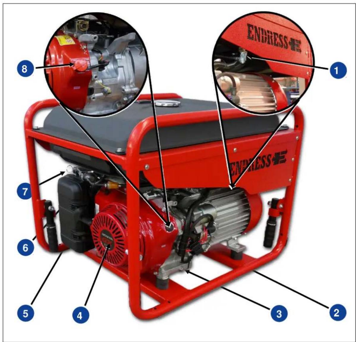
Figure 3-3: Engine and maintenance side components
1 Fuel valve
2 Oil filling and checking screw
3 Oil drain screw
4 Engine
5 Recoil starter grab handle
6 Engine air filter
7 Manual choke *
8 Engine switch *
* only in version started by hand
3.4 Control panel components

Figure 3-4: Control panel components *
1 Line circuit breaker (and FI protection switch *)
3 Engine start switch **
5 Multi-functional display
7 CEE socket 400V / 3\~
9 Test button for ISO monitoring *
11 Fuse for remote start power socket *
13 CPC remote start power socket*
2 Switch for EcoTronic (speed reduction) (under hinged window) *
4 Choke switch **
6 Schuko (shockproof) power sockets 230 V / 1\~
8 Reset button for ISO monitoring *
10 Insulation fault indicator light *
12 EMERGENCY-STOP switch ***
14 Fuse for ECOtronic
Function und operating principle
The synchronous generator is firmly coupled to the drive engine. The aggregate is installed in a stable frame with a cover hood and equipped with flexible and low vibration suspension elements.
Splash-proof earthed power and CEE sockets with a nominal voltage of 230 and/or 400 V/50 Hz supply the power.
An integrated voltage regulator controls the voltage of the generator in the nominal speed range of the generator.
The generator is designed for mobile operation with one or more electrical consumers (safety-separated circuit according to VDE 100, Part 551). The protective conductor of the ground contact socket assumes the function of the potential equalisation line.
Notes
4. Operation

The operation of the generator is described in this section.
4.1 Transporting the generator
Proceed as follows to transport the generator.
Requirements
The following requirements must be met:
• The generator must be turned off
- The generator must have cooled down.
- The fuel valve is in the "OFF" position.
- At least one person per carrying handle
- Carrying strap with an adequate load capacity for loading by crane

WARNING!
A slipping or falling device can crush hands or feet.
• Take the weight of about 94 - 113kg into account.
- Carry the device with one person on carrying handle.
- Only lift the device using the carrying handles.
- Raise/lower device evenly.
- Walk slowly.
Carrying the generator
- Unfold carrying handles.
- Lift generator evenly.
- Carry the generator to the work site.
- Lower generator evenly.
- Fold carrying handles.
√ The generator has been carried to its work site.
Loading by crane
To load with a lifting device, only use suitable aids which can be led through the bracket on the upper frame (see Figure 4-1). It is only in this way that the generator can be securely lifted horizontally and secured against sliding.

WARNING!
Danger of severe or mortal injuries being incurred from falling loads.
- Never stand under or close to a suspended load, also not to provide assistance.
- Ensure that there is no person in the area of swivel of the lifting device.
- Use all suitable measures to prevent the suspended load from swaying.
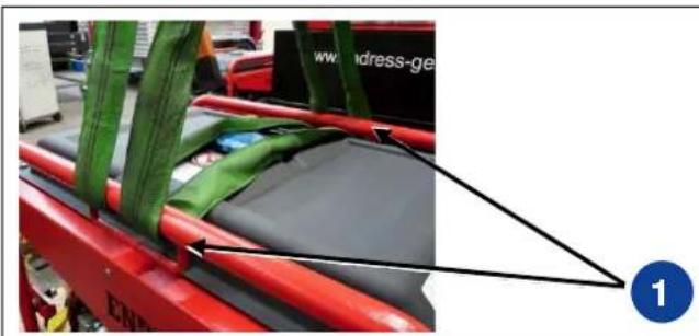
Figure 4-1: Attachment of the carrying straps
- Lead a suitable carrying strap through the bracket (Figure 4-1-(1)) provided for this in the upper frame area.
- Hook carrying strap with locking clip into the lifting device.
- Lift generator evenly.
- Carry the generator to the work site.
- Lower generator evenly.
- Remove carrying strap.
√ The generator has been carried to its work site.
4.2 Setting up the generator
Proceed as follows to set up the generator.
Requirements
The following requirements must be met:
- An even and firm substratum outdoors
• There are no inflammable materials at the operating site - There are no explosive materials at the operating site

WARNING!
Leaking engine oil and petrol can contaminate the soil and groundwater.
- Prevent leaking of engine oil and petrol.
Setting up the generator
Set up the generator as follows:
- Prepare the work site.
- Transport the generator to the work site.
√ The generator is set up and ready for use.
4.3 Refuelling the generator
Proceed as follows to refuel the generator.
Requirements
The following requirements must be met:
• the device must be shut off.
• the device must be cooled down.
• there must be an adequate air supply and air removal
- Appliances switched off or disconnected

DANGER!
Danger to life and danger from combustions Leaking engine oil and petrol can ignite or explode on hot parts of the device.
- Prevent leaking of engine oil and petrol.
- Never refuel when the engine is running.
- Allow device to cool off before refuelling.
- Avoid open flames and sparks.

WARNING!
Leaking engine oil can contaminate the soil and groundwater.
- Do not fill the tank completely.
- Use a filling aid.

WARNING!
Using the wrong fuel will destroy the engine.
- Only refuel with lead-free regular grade petrol RON 95 or higher.
Refuelling the device
Refuel the generator as follows:
- Unscrew tank cover.
- Insert filler aid into the filler neck.
- Add petrol.
- Remove filler aid.
- Screw on tank cap
√ The device is refuelled.
4.4 Starting the generator
At this location starting of the generator is described for manual assignment, that is with consumers which are connected to the power sockets of the generator. To operate as a replacement network plant (operating mode "supplying power to a building"), see Chapter 4.7.2
Requirements The following requirements must be met:
- checked and tested for electrical safety
• there must be fuel in the tank. - sufficient oil level (fill with engine oil before initial use, see the engine operating and maintenance instructions)
• there must be an adequate air supply and air removal - Fit push-on exhaust gas pipe (special accessory) if needed
• Appliances switched off or disconnected

WARNING!
Operating fluids can burn or explode.
- Prevent leaking of engine oil and petrol.
- Do not use starting aids.
- Avoid open flames and sparks.

WARNING!
Risk of death due to poisoning or asphyxiation. Engine exhaust gases contain poisonous carbon monoxide gas (CO) and carbon dioxide gas (CO2) .
- Provide for sufficient ventilation.
- In the case of unfavourable ventilation conditions, use a permitted exhaust hose.
- Only operate the generator outdoors.

WARNING!
Hot parts can ignite flammable and explosive materials.
- Avoid flammable materials at the operating site.
- Avoid explosive materials at the operating site.

WARNING!
Heat or moisture destroys the device.
- Avoid overheating (sufficient ventilation).
- Avoid moisture.
Starting the motor
Proceed as follows to start the generator in the hand start version.

Figure 4-2: Hand start operating controls

Figure 4-3: Hand choke position
Started by hand:
- Turn fuel cock clockwise into the uppermost position (Figure 4-2-(1)), to open it.
- Turn the hand choke (Figure 4-3-(1)) to the left into the (Figure 4-3-(2)) position.
-
Turn engine switch (Figure 4-2-(3)) into the position "ON I".
-
Start the engine by briskly pulling the recoil starter (Figure 4-2-(4)).
√ The motor starts.
- Bring the choke (Figure 4-3-(1)) slowly to the right into the position (Figure 4-3-(3)).
√ The engine has started.
NOTE The electrical devices can be connected and/or hooked up after a warming-up phase of about one minute.
Proceed as follows to start the generator in the Electrostart version.
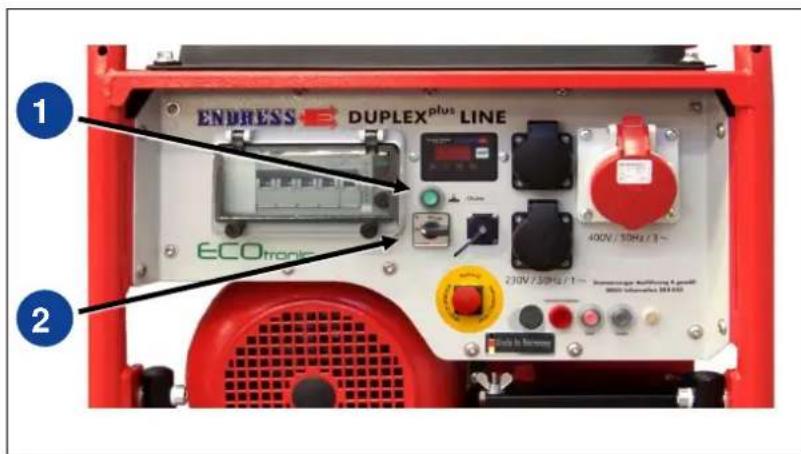
Figure 4-4: Electrical start
Electrical start
-
Turn fuel cock clockwise into the uppermost position (Figure 4-2-(1)), to open it.
-
Press the choke button (Figure 4-4-(1)) and hold down.
-
Turn the engine start switch (Figure 4-4)-(2)) fully to the right into the "START" position.
√ The motor starts.
NOTE Only activate the starter briefly (max. 5-10 seconds). Never start or run the engine with the battery disconnected.
- Release the engine start switch (Figure 4-4-(2)); the switch springs into the "RUN" position.
- Release choke button (Figure 4-4-(1)).
√ The engine has started.
NOTE The electrical devices can be connected and/or hooked up after a warming-up phase of about one minute.
4.5 Switching the generator off
Proceed as follows to shut down the generator.

WARNING!
Hot parts can ignite flammable and explosive materials.
- Avoid flammable materials at the operating site.
- Avoid explosive materials at the operating site.
- Allow the generator to cool down.
Switching the device off The device is switched off as follows:
Started by hand:
- Switch off or disconnect consumers.
- Continue to run the engine without load for about two minutes.
- Turn engine switch (Figure 4-2-(3)) downwards into the "OFF" position.
√ The engine comes to a standstill and the generator is switched off.
Electrical start
- Switch off or disconnect consumers.
- Continue to run the engine without load for about two minutes.
- Turn the engine start switch (Figure 4-4-(2)) to the left into the "OFF" position. Special considerations must be considered (see Chapter 5.3) for remote operation.
√ The engine comes to a standstill and the generator is switched off. - Turn fuel cock anti-clockwise into the horizontal position (Figure 4-2-(2)), to close it.
WARNING!
Explosion hazard due to escaping fuel

- Close the fuel cock (petrol feed) as soon as possible after ending operation of the generator.
- Close the fuel cock after use before transport.
4.6 Connect up to consumers
Selection of the correct connection decisively depends on the intended operating mode. In doing always observe the instructions regarding both operating modes "on-site operation" and "supplying power to a building" in Chapter 4.7, if your generator with this option. Select the required operating mode.
Requirements
The following requirements must be met:
- The correct operating mode on the changeover switch (Figure 4-5-(2)) is selected.
• The generator is started (see Chapter 4.4) - All consumers to be connected are switched off.

WARNING!
Danger to life due to electrocution!
- Never connect the generator to an existing electrical grid.
- Never insert the plug in a wet condition.
- Only create plug connections with dry hands.
You can connect consumers dependent on the selected operating mode according to the following table to the following 12 V power sockets:

Figure 4-5: Connect up to consumers
| ONLY supplying power to a building | |
| ? | CEE socket 400V / 16 A / 3~ / 7h-position |
| ONLY on-site operation | |
| ? | CEE socket 400V / 16 A / 3~ / 6h-position |
| ? | Schuko attachment sockets 230 V / 16 A / 1~ |
Connect up to consumers
This is how you connect the consumer to the 12 V power sockets on the control panel:
- Fold up the cover of the power socket upwards (for power socket from IP54 and turn latch counterclockwise and take off the cover off).
- Insert the connector (for connectors from IP54 latch on the connector clockwise up to the stop).
√ The consumer is connected to the generator.
NOTE Selection of the correct power socket strongly depends on the operating modes as described below!
4.7 Changeover of operating mode (II / TN-S)
The following section explains the exact procedure for operation of the generator and the connection of consumers under various operating conditions. The switchover function offers you the possibility to operate the generator optionally for on-site operation with a mobile distributor system or for supplying power to a building in a fixed plant.
The selection of a suitable operating mode is prescribed dependent on the purpose.

CAUTION!
ONLY switch over the changeover switch operating mode (Fig. 4-5-(2)) for a stopped generator!!
- The correct operating mode (supplying power to a building or on-site operation) must be selected before starting the generator.
4.7.1 Incident scenes operation
In the operating mode “1st on-site operation”, the generator is designed for manual or automatic operation (remote start) with one or more electrical consumers (according to VDE 100, Part 551). The protective conductor of the ground contact socket assumes the function of the potential equalisation line.
The power tap in the "On-site operation" operating mode takes place over a spray water protected Schuko 12 V connection with a nominal voltage of 230 V / 50 Hertz 1\~ or over a CEE-12 V connection 400 V / 50 Hertz / 6 h 3\~, see Chapter 4.6.
To do this select the "On-site operation" operating mode at the changeover switch (Fig. 4-5-(2)).
For the following worksteps proceed as described in Chapter 4.4. If the generator is fitted with insulation monitoring with shutoff, proceed in the "On-site operation" operating mode, as described in Chapter 5.2, before connecting to consumers.
4.7.2 Supplying power to a building
The operating mode "Supplying power to a building" serves to feed stationary plant such as that found in residential buildings or facilities according to VDE 0100 Part 551:2017-02 Annex ZC. The generator serves as the emergency power supply to maintain the power supply in a case of failure of the public power supply.

DANGER!
For further steps there is the requirement that the building be fitted with emergency power infeed was fitted out with this by a specialist company under the supervision of an electrician, and that this was according to VDE 0100 Part 410, and VDN. The fault protection must, in particular, be secured by an on site RCD.

DANGER!
The power feed in socket with the 7h position may ONLY be used for supplying power to a building!
Note
Feed into the fixed plant takes place over a flexible connection line (H07RN-F or comparable) in the on site installed feed distributor over the CEE power socket 400 V / 50 Hz / 7h 3\~ (see Fig. 4-5-(1)). All other 12 V power sockets are not energized and not usable in this operating mode.
Ensure that the flexible connection line is suitable for the selected operating conditions and power output requirements.
There is a suitable plug with 7h coding in the scope of delivery for the power feed in socket for adaptation of a feed cable.

Figure 4-6: Feed plug in the scope of delivery
Create the power feed connection
Requirements The following requirements must be met:
- generator is ready for operation
- the changeover switch of the building side feed distributor is in the position "Network" or "0" (analogously).
Create the power feed connection
Proceed as follows in order to create a power feed connection between the generator and the on-site installed feed distributor:
- select the operating mode "Supplying power to a building" at the changeover switch (Fig. 4-5-(2)).
- Start the generator.
- Connect the flexible connection with the CEE-12 V power socket 400 V / 50 Hz / 7 h 3\~ with the black colour coding (see Fig. 4-5-(1)).
- Connect the flexible connection line with the power socket to the on site installed feed distributor.

DANGER!
Ensure that there is a clockwise rotating field applied to the feed distributor at the sides of the emergency power infeed. If there is no appropriate direction of rotation indicator on the feed distributor, the rotational field must be checked by a qualified electrician (see Fig. 4-7).

DANGER!
Ensure that all consumers in the distribution network of the fixed plant are switched off or disconnected from the network before you switch over the feed distributor to emergency power.
- Switch the changeover switch on the feed distributor into the position "Emergency power" (analogously).
√ The emergency power supply is created.
√ The fixed plant is fed by the generator.
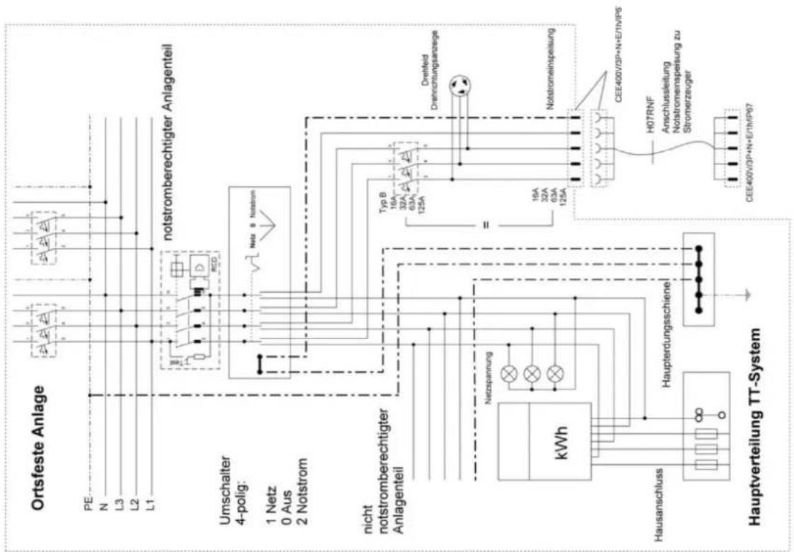
Figure 4-7: Equipment specification example Main distribution TN system / TT system
4.8 ECOtronic (idle down)
Proceed as follows to operate the generator with idling speed reduction.
Requirements
The following requirements must be met:
- generator is ready for operation
- generator has been started (see 4.4)
Switching the idle down on
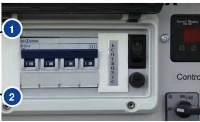
Figure 4-8: Idle down rocker switch
Switching the idle down on
Switch on idle speed reduction as follows:
- Move the rocker switch (Figure 4-8-(1)) into the 'I' (ON) position.
√ Idle down is activated.
ATTENTION
Idle down is activated as soon as the motor starts and it reduces the motor speed to approx. 1,800 revs/min. The engine speed will be increased to the nominal speed as soon as a load is switched on. The motor will continue to run for 40 seconds at a nominal speed after the load has been switched off, before the speed is reduced to approx. 1,800 revs/min. again.
The motor always runs in the nominal speed range if the rocker switch is in the "0" OFF position.
Switching idle down off
Switch the idle down off as follows:
- Move the rocker switch (Figure 4-8-(1)) into the '0' (OFF) position.
√ Idle down is switched off.
4.9 Monitoring the operating status via the "ECD 02 control display"
The display (see Figure 4-9) is always active when the generator is running.

Figure 4-9: Multi-functional display
- The current voltage (V) is displayed after the generator starts (see Figure 4-9-(1)), shown by means of the illuminated "V\~" symbol for Volt.
- Press the button once (see Figure 4-9-(2)) and the current frequency (Hz) will be displayed, shown by means of the illuminated "Hz" symbol for Hertz.
√ The display has been switched over. - Press the button once again (see Figure 4-9-(2)) and the operating hours (h) will be displayed, shown by means of the illuminated "h\~" symbol for hours.
√ The display has been switched over. - Press the button once again (see Figure 4-9-(2)) and the operating hours (h) will be displayed again on the display for the current voltage in Volt and the sequence begins from the beginning.
√ The display has been switched over.
4.10 Putting the generator out of service
The generator should be put out of service if it is not required for more than 30 days. It is best to use a cloth to cover the generator.
NOTE Correct putting out of service is described in the engine operating manual and maintenance instructions.
4.11 Disposal
Due to environmental protection considerations the generator, battery, engine oil etc. cannot simply be thrown into the refuse bin. Observe all local laws and regulations concerning correct disposal of such parts and substances. Your authorised ENDRESS generator dealer is happy to advise you.
Please observe the pertinent environmental protection regulations when disposing of the old oil. We recommend bringing the oil in a closed container to an old oil collection centre for disposal. Do not throw away used engine oil into the refuse bin or pour it onto the ground.
An inappropriately disposed of battery can damage the environment. Always comply with the local regulations when disposing of batteries. Please contact your ENDRESS maintenance dealer for a replacement.

Notes
5. Using special fittings / accessories
5.1 RCD fault current safety equipment / FI protection switch
The FI protection switch option can only be supplied by the factory.
The FI protection switch (RCD) serves as a protective measure against dangerous body currents according to DIN VDE 0100 Part 551. For a start-up and operation on building and installation sites, the generator in this equipment specification according to DGUV information 203-032 is classified as a generator of the equipment specification C and is fitted with the following marking:

It is essential to observe the regulations and safety instructions of the DGUV information 203-032 mentioned in order to achieve body protection for all persons working in the connected distributor network.
WARNING!
Danger to life due to electrocution.
- Use of an RCD (FI protection switch) as body protection absolutely requires orderly earthing of the generator. This must occur for every initial operation by a qualified electrician.
- The effectiveness of this protective measure should be regularly checked by an electrician.
Additionally, the operating personnel must check the mechanical operation of the release for every putting into operation by activating the test button on the residual current protection device (RCD) (see Figure 5-1-(2)).

Figure 5-1: FI protection switch
Checking the FI protection switch:
-
The generator must have been started (see 4.4).
-
Put the protection switch (see Figure 5-1-(1)) into Position 1.
-
Activate the test switch (seeFigure 5-1-(2)).
√ The switch position displays the result (seeFigure 5-1-(1)):
| Symbol | Significance |
| Position 1 | Protection switch does not trigger.Fi protection switch is defective. |
| Position 0 | Protection switch triggers.FI protection switch is working properly. |
Table 5.1: FI protection switch test
√ The device has been tested in compliance with DIN VDE 0100-551.
- Bring protection switch (Figure 5-1-(1)) back into Position 1 in order to be able to operate consumers on the generator again.
5.2 Insulation monitoring with switch off
The insulation monitoring serves to provide electrical safety of the generator as well as all connected consumers and cable connections during continuous operation.
Important note
The operating personnel must check the function of the shutoff for every start-up by pressing the test button on the insulation monitoring (see also Chapter 2.7 Electrical safety check).
Requirements
The following requirements must be met for the test:
• generator has been started (see 4.4)

Figure 5-2: Insulation monitoring
Testing the insulation monitoring:
- Unplug the device
- The circuit breaker must be in Pos. 1.
- Press the test button (see Figure 5-2-(2))
√ The lamp (Figure 5-2-(3)) and the position of the circuit breaker (Figure 5-2-(4)) indicates the result:
| Lamp | Result | Significance |
| lights up red | Circuit breaker jumps to Pos. 0 | Insulation monitoring is OK |
| stays off | Circuit breaker stays in Pos. 1 | Insulation monitoring is defective |
| stays off | Circuit breaker jumps to Pos. 0 | Lamp defective |
Table 5.2: Insulation monitoring plus switching off
√ The insulation monitoring test has been run.
- After checking, the Reset button (see Figure 5-2-(1)) must be pressed and the circuit breaker must be turned back to Pos. 1 so that the unit can be used again.
Insulation monitoring whilst running:
- Plug in the device and switch on.
√ The lamp (see Figure 5-2-(3)) and the position of the circuit breaker indicates the result:
| Lamp | Result | Significance |
| lights up red | Circuit breaker jumps to Pos. '0' | Insulation fault (≤ 23 kΩ) |
| stays off | Circuit breaker stays in Pos. 1 | Connected unit is OK |
Table 5.3: Insulation monitoring whilst running without switching off
√ If an insulation fault exists and the unit was previously OK when tested without a device connected (see above), the insulation fault has been caused by the device.
- The reset button (see Figure 5-2-(1)) must be pressed after switching off and disconnecting the consumer and the circuit breaker must be turned to Pos. 1 so that the unit can be used again.
5.3 Remote start device
Proceed as follows to operate the generator using the remote start device.
Requirements
The following requirements must be met, before you connect the remote start device:
- Generator is ready for operation
- Engine start switch (Figure 4-4-(3)) is in the "OFF" position.
- All consumer are switched off or disconnected from the generator.

Figure 5-3: Remote start device
Connecting up a remote start device
Proceed as follows to connect a cable remote control (not in the scope of delivery).
- Remove protective cap of the CPC remote start socket (Figure 5-3-(2)) counterclockwise.
- Insert plug of the connecting cable of the cable remote control in the correct location in the remote start socket.
- Turn the locking ring of the connector clockwise up to the stop.
- Route the connecting cable securely up to the operating point.
√ Remote start device is ready for use.
Disconnecting the remote start device
Proceed as follows to disconnect a cable remote control.
- Switch the generator (engine start switch (Figure 5-3-(3)) into the "OFF" position!
- Turn the locking ring on the connector counterclockwise until the lock is released.
- Pull off connector for connecting cable.
- Screw the protective cap onto the remote start socket.
√ Remote start device is disconnected.
Operation of the remote start device
Proceed as follows to operate the generator over the remote start device using cable remote control.
Requirements
The following requirements must be met:
- Generator is ready for operation
• Engine start switch (Figure 5-3-(3)) is in the "OFF" position.
• The cable remote control is fitted correctly.
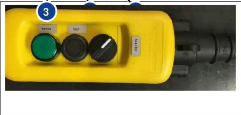
Figure 5-4: Cable remote control
Start the engine using remote start
- Turn the switch (Figure 5-4-(1)) to the "On" position.
- Press the "Start-operation" button (Figure 5-4-(2)).
√ The engine is started. - Release the "Start" button (Figure 5-4-(2)).
√ The engine has started.
√ The operation indicator light (Figure 5-4-(3)) lights up.
NOTE Only activate the starter briefly (max. 5-10 seconds). Never unclamp the starter battery when the engine is running.
Switch off the engine using remote start
- Switch off or disconnect consumers.
- Continue to run the engine for about two minutes.
- Turn the switch (Figure 5-4-(1)) to the "Off" position.
√ The generator is switched off.
√ The operation indicator light (Figure 5-4-(3)) lights up.
NOTE
Ensure that the engine start switch (Figure 5-3-(3)) of the generator remains in the "OFF" position. Otherwise the control circuit on the generator will still be energized which can cause the starter battery to discharge.
5.3.1 EMERGENCY-STOP switch
In the equipment specification with a remote start device, the generator is fitted with an EMERGENCY STOP function. In this way one can ensure that the generator can always be stopped as quickly as possible in a dangerous situation, or if there is a fault, over the clearly marked EMERGENCY STOP switch (Figure 5-3-(1)) on the device.
Proceed as follows to switch off the generator in an emergency using the EMERGENCY STOP switch.
Requirements
- The EMERGENCY STOP switch must be available to operate at any time without fulfilment of any requirements.
Trigger the EMERGENCY-STOP switch
- Actuate the red knob on the EMERGENCY STOP switch (Figure 5-3-(1)) by pressing or pounding
√ The generator is stopped
√ The line circuit breaker (Figure 5-2-(4)) triggers (Position 0)
√ The EMERGENCY STOP switch is locked in the Off position.
Unlocking the EMERGENCY-STOP
Proceed as follows to switch the generator on again after using the EMERGENCY STOP switch.
- Turn knob on the EMERGENCY STOP switch (Figure 5-3-(1)) until is springs out of the locked position.
- Bring the line circuit breaker into Position 1
√ The EMERGENCY STOP lockout is removed.
√ The generator can now be started as usual.
6. Maintenance

Generator maintenance is described in this section.
Only personnel from the manufacturer may carry out maintenance or repair work not described in this section.
6.1 Maintenance plan
The maintenance work specified in this summary must be carried out after the indicated time intervals.
| Maintenance work | Time interval in operating hours [h] | ||||
| every 8 h / daily | every 50 h / (weekly) | every 200 h / (monthly) | every 300 h | every 500 h | |
| Checking the electrical safety | before each start-up | ||||
| Check and top off motor oil | |||||
| Check fit of screws, nuts, and bolts | |||||
| Changing the oil | (X) 1 | X (every 100 h) | |||
| Clean spark plugs | X (every 100 h) | ||||
| Cleaning the air filter | X | ||||
| Replace air filter insert | X | ||||
| Clean the coarse fuel filter | X | ||||
| Insert spark plug electrodes | X | ||||
| Check and adjust valve clearance | X | ||||
| Remove combustion residues from the cylinder head | X | ||||
| Clean and adjust carburettor | X | ||||
| Overhaul engine whenever necessary | every 1000h(2) | ||||
Table 6.1: Generator maintenance plan
1) After the first 20 operating hours
2) To be undertaken by a specialist or an Endress service station.
6.2 Maintenance work
Only authorised personnel are allowed to carry out maintenance tasks.
Carry out all maintenance tasks specified in the maintenance plan according to the specifications in the enclosed operating and maintenance instructions for the engine. These operating and maintenance instructions of the engine manufacturer are an integral component of these operating instructions.
6.2.1 Motor oil

WARNING!
Leaking engine oil can contaminate soil and groundwater.
- Use an oil collection container.
• Recycle used motor oil

WARNING!
Engine oil can be hot — risk of burns.
- Allow motor to cool
Requirements
The following requirements must be met:
- The engine should ideally be slightly warm (allow a cold engine to run for 5 min., then stop it and allow it to cool for 2 min.).

Figure 6-1: Oil dipstick and oil drain plug
Checking the oil Check the oil level as follows:
- Unscrew the grey oil level gauge (Figure 6-1-(1)).
- Use a clean cloth to wipe the oil level gauge (Figure 6-1-(1))
- Reinsert the dipstick (Figure 6-1-(1)) and take it out again. The oil level read on the dipstick must be within the range which is specified in the maintenance and operator's manual from the engine manufacturer. One should otherwise top up or drain off oil to correct the level!
√ The oil level has been checked.
Refilling with oil Refill with oil as follows:
- Unscrew the grey oil level gauge (Figure 6-1-(1)).
- Fill with oil using a filling aid.
- Check oil level and add oil if necessary.
√ The engine has been refilled with oil.
Changing the oil Change the oil as follows:
- Put the unit on a raised support (e.g. wooden blocks, workbench)
- Put a tray under the oil drain screw (Figure 6-1-(2)) in position to collect the oil.
- Unscrew the oil drain screw (Figure 6-1-(2)) and allow the oil to drain off completely.
- Engine oil has been drained.
- Screw the oil drain screw (Figure 6-1-(2)) in again.
- Then refill with fresh oil. (see "Refilling with oil").
√ The oil has been changed.
WARNING!

Using the wrong motor oil will destroy the motor.
- Only use engine oil according to instructions given in the maintenance and operator's manual from the engine manufacturer!
- In doing so also observe the actual ambient and operating conditions.
- Never mix in a commercial additive with the oil.

WARNING!
The oil escapes immediately after unscrewing the oil drainage screw.
6.2.2 Charging the battery
The battery can discharge after a longer immobilisation period or excessive power consumption in the control circuit of the generator.
Always remove the starter battery before charging (see Chapter 6.2.3). Exactly observe the handling instructions provided by the battery manufacturer.

WARNING!
A highly explosive electrolytic gas mixture develops from gassing when charging batteries.
- Fire, formation of sparks and smoking are strictly forbidden.
- Avoid short circuits when handling cables and electrical devices, as well as electrostatic discharge.

DANGER!
Danger due to chemical burn of the battery explodes. Aggressive vapours will be emitted if it is overloaded.
- Exactly observe the handling instructions provided by the battery manufacturer.
- Never charge the battery in an installed condition.
- Only charge the battery at well ventilated locations.
6.2.3 Replacing the starter battery
- First pull back the black terminal protective cap on the negative cable of the battery and loosen the cable.
- Loosen both wing nuts (Figure 6-2-(1)) to allows the battery holder (Figure 6-2-(2)) to be removed.
- Then pull back the red terminal protective cap on the positive cable of the battery and loosen the cable.
- Remove the battery from the battery compartment.
√ Battery is disconnected.

Figure 6-2: Replacing the battery
- Prepare a new battery.
- Put the battery back into the battery compartment.
- Screw the battery onto the positive terminal first.
- Put the battery holder back.
- Screw the cattery cable onto the negative-terminal last.
- Put on the terminal protection cap.
√ The battery has been replaced.

WARNING!
The Endress battery is maintenance-free throughout its entire service life.
- Never open the battery — this may destroy it.
7. Troubleshooting

This section describes problems during operation that authorized personnel can remove.
Each occurring problem is described with its possible cause and the respective corrective measure.
The authorised personnel must immediately shut down the generator and inform the responsible and authorised service personnel if a problem cannot be solved with the aid of the following table.
| Malfunction | Possible cause | Correction |
| No or insufficient voltage available during idling. | The rotational speed of the engine was adjusted afterwards. | Call service staff. |
| The electronic controller has been altered. (for ESE 606 DHG-GT (ES) Duplex | Call service staff. | |
| The electronic controller is defective. (for ESE 606 DHG-GT (ES) Duplex | Call service staff. | |
| Strong voltage fluctuations occur. | The engine runs irregularly. | Call service staff. |
| The speed control works erratically or insufficiently. | Call service staff. | |
| The engine does not start. | The engine is being operated incorrectly. | Follow the engine operating manual instructions. |
| Maintenance of the engine was inadequate. | Follow the engine maintenance instructions. | |
| Too little fuel in the tank. | Refuel | |
| The fuel filter is clogged. | Replace the fuel filter. | |
| Bad fuel in the tank. | Call service staff. | |
| The ignition cable does not have any connection to the spark plug. | Attach ignition cable to the spark plug. | |
| The choke is not activated in a cold condition. | Actuate choke. | |
| The engine does not rotate. | Engine defective. | Call service staff. |
| The engine smokes. | Too much oil in the engine. | Drain excess oil. |
| Paper element of the air filter is dirty or oil-soaked. | Clean paper element or replace if necessary. | |
| Foam element of the air filter is dirty or dry. | Clean foam element and if necessary moisten. | |
| The engine starts briefly and then shuts down. | Too little fuel in the tank. | Refuel |
| Ventilation holes on tank cover are clogged. | Clean ventilation holes. | |
| The oil level is too low. | Add oil. | |
| The fuel filter is clogged. | Replace the fuel filter. | |
| Carburettor/fuel filter/tank are covered with resin. | Call service staff. | |
| Starter battery has no power. (of electrical start equipment) | Battery is discharged. | Charge battery. |
| Battery is defective. | Exchange battery. | |
| Battery terminals are oxidized. | Clean battery terminals and if necessary apply terminal grease. | |
| The power output is insufficient. | The electronic controller has been altered. (for ESE 606 DHG-GT (ES) Duplex | Call service staff. |
| The electronic controller is defective. (for ESE 606 DHG-GT (ES) Duplex | Call service staff. | |
| Maintenance of the engine was inadequate. | Follow the engine maintenance instructions. | |
| Too much power is drawn. | Reduce power draw. | |
| The generator runs jerkily. | The generator is loaded beyond the nominal output. | Reduce power draw. |
| Reduce idle speed does not work. | Rocker switch is in the OFF position. | Set the rocker switch to the ON position. |
| Fuse is blown. | Replace the fuse. | |
| The generator cannot be switched off using the remote start device | The engine start switch on the control panel stands in the “RUN” position | The engine start switch on the control panel stands in the “OFF” position for a remote start. |
Table 7.1: Troubleshooting during generator operation
Notes
8. Technical specifications

The technical specifications concerning use of the generator are described in this section.
| Name | Value | ||||
| ESE 406 HG-GT (ES) Duplex | ESE 506 HG-GT (ES) Duplex | ESE 606 (D)HG-GT (ES) Duplex | |||
| Nominal output | 4.0 | 5.0 | 6.0 ~3 | 4.8 ~1 | [kVA] |
| Nominal output factor | 1 | 1 | 0.8 ~3 | 0.9 ~1 | [cosφ] |
| Nominal frequency | 50 | 50 | 50 | [Hz] | |
| Nominal speed | 3000 | 3000 | 3000 | [min-1] | |
| Rated voltage | 230 | 230 | 400 ~3 | 230 ~1 | [V] |
| Rated current | 17.4 | 21.7 | 8.7 ~3 | 17.4 ~1 | [A] |
| Weight (ready for use) | 94 (103) | 102 (111) | 104 (113) | [kg] | |
| Tank capacity | 33 | 33 | 33 | [l] | |
| Fuel consumption (at a 75% load)1) | 1.6 | 2.1 | 2.1 | [l/h] | |
| Length | 780 | 780 | 780 | [mm] | |
| Width | 550 | 550 | 550 | [mm] | |
| Height | 595 | 595 | 595 | [mm] | |
| Noise pressure level at the workplace LpA2) | 89 | 89 | 89 | [db (A)] | |
| Sound pressure level at a distance of 7m LpA3) | 64 | 60 | 60 | [db (A)] | |
| Sound power level LWA3) | 97 | 97 | 97 | [db (A)] | |
| Alternator, system of protection | IP 54 | IP 54 | IP 54 | ||
Table 8.1: Generator technical data
1) Average value; these can show deviations in an individual case and are therefore non-binding
2) Measured at a distance of 1 m and a height of 1.6 m in accordance with ISO 3744 (Part 10)
3) Measured in accordance with ISO 3744 (Part 10)
Ambient conditions
| Name | Value | Unit |
| Setting up height above sea level | < 100 | [m] |
| Temperature | < 25 | [°C] |
| Relative air humidity | < 30 | [%] |
Table 8.1: Ambient conditions for the generator
Reduced power
| Power reduction | for each additional | Unit |
| 1 % | 100 | [m] |
| 4 % | 10 | [°C] |
Table 8.2: Generator power reduction dependent on ambient conditions
Distribution network
| Line | max. line length | Unit |
| HO 7 RN-F (NSH öu) 1,5 mm2 | 60 | [m] |
| HO 7 RN-F (NSH öu) 2,5 mm2 | 100 | [m] |
Table 8.3: Maximum line length of the distribution network as a function of the cable cross-section

The general limitation of 100 m for the overall length was selected in the interest of safe handling during practical use. Larger dimensioning of the distribution network is only to be undertaken by a qualified electrician or trained personnel.
Notes
9. Replacement parts

This section provides an overview of the most important replacement parts and their designation. Please contact our customer service to obtain original replacement parts for your device at
Tel. +49-(0)-7123-9737-44
Note the article number and serial number of your device beforehand to exactly identify the correct replacement part number. You will find these details on the type plate (see Table 2.2).
9.1 Frame / engine / generator
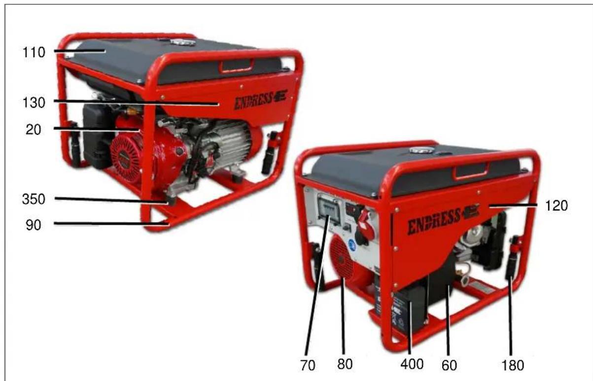
Figure 9-1: Replacement parts for the frame / engine / generator
| Item | Article name |
| 20 | Engine |
| 60 | Silencer |
| 70 | Hinged window No. 40978 |
| 80 | Gen syn. |
| 90 | G gram BG2 |
| 110 | G tank V02 |
| 120 | M-side panel R |
| 130 | M-side panel L |
| 180 | Carrying handle, black |
| Inset handle made of soft PVC | |
| KAPSTO sealing cap | |
| 350 | Vibration damper Form B |
| 400 | 12V/20Ah battery |
| 690 | Operating instructions for the 406-606 |
Table 9.1: Replacement parts for the frame / engine / generator
9.2 Electrical junction box
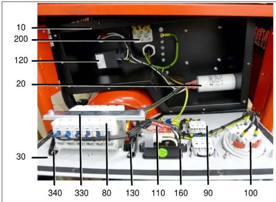
Figure 9-2: Replacement parts Electrical junction box
| Item | Article name |
| 10 | M - E housing in plastic |
| 20 | 2HC40XD capacitor |
| AVR controller | |
| 30 | Control panel |
| 80 | Line circuit breaker |
| 90 | 230 V / 16 A Schuko power socket |
| 100 | 400V / 16 A 5P CEE socket |
| 110 | EMERGENCY-STOP switch |
| 120 | Idle controller for BG 112 |
| 130 | Rocker switch green, 1-pin |
| 140 | FPG1 fuse holder |
| 150 | 5 x 20 mm fine-wire fuse |
| 160 | 4/1 Display GPD-01 |
| 170 | Green push button closer |
| 180 | Transparent seal cap |
| 190 | EFXY3R2 interference elimination filter |
| 200 | 6-pin motor terminal board |
Table 9.2: Replacement parts Electrical junction box
GARANTIEERKLÄRUNG
DUPLEX PLUS STROMERZEUGER

- PUBLISHER ENDRESS
- CAUTION
- IMPORTANT NOTES ON COMMISSIONING AND OPERATION OF THE CONSTRUCTION AND ASSEMBLY LOCATIONS
- PROTECTIVE MEASURES AND RULES OF BEHAVIOUR
- TABLE OF CONTENTS
- GENERAL INFORMATION....9
- GENERAL SAFETY REGULATIONS....13
- THE GENERATOR ESE 406 - 606 (D)HG-GT (ES) DUPLEX .....29
- OPERATION....35
- USING SPECIAL FITTINGS / ACCESSORIES....54
- MAINTENANCE ....61
- TROUBLESHOOTING....66
- TECHNICAL SPECIFICATIONS....69
- REPLACEMENT PARTS....72
- WRITTEN GUARANTEE....75
- PROOF OF MAINTENANCE ....78
- LIST OF ILLUSTRATIONS
- LIST OF TABLES
- GENERAL INFORMATION
- 1.1 FURTHER DOCUMENTS AND DOCUMENTATION
- 1.2 SAFETY SYMBOLS
- WARNING OF A GENERAL HAZARD
- POTENTIALLY EXPLOSIVE MATERIALS
- DANGEROUS ELECTRICAL VOLTAGE
- POISONOUS SUBSTANCES
- WARNING CONCERNING FALLING LOADS
- ENVIRONMENTALLY DAMAGING SUBSTANCES
- HOT SURFACES
- GENERAL SAFETY REGULATIONS
- 2.1 IMPORTANT SAFETY WARNING
- THE FOLLOWING ACTIONS ARE NOT PERMITTED
- 2.1.1 INTENDED USE
- 2.1.2 FORESEEABLE INCORRECT USE OR INAPPROPRIATE HANDLING
- 2.1.3 RESIDUAL RISKS
- RISK OF DEATH
- RISK OF INJURY
- ENVIRONMENTAL HAZARDS
- MATERIAL DAMAGE TO THE GENERATOR
- MATERIAL DAMAGE TO OTHER PROPERTY
- LIMITS TO PERFORMANCE OR FUNCTIONALITY
- 2.2 OPERATING PERSONNEL – QUALIFICATIONS AND OBLIGATIONS
- 2.3 PERSONAL PROTECTIVE EQUIPMENT
- 2.4 DANGER ZONES AND WORK AREAS
- 2.5 SIGNS ON THE GENERATOR
- 2.6 GENERAL SAFETY INSTRUCTIONS
- ENVIRONMENTAL PROTECTION
- 2.7 CHECKING THE ELECTRICAL SAFETY
- THE GENERATOR ESE 406 - 606 (D)HG-GT (ES) DUPLEX
- 3.1 VIEWS OF THE GENERATOR
- 3.2 COMPONENTS ON THE OPERATING AND EXHAUST SIDE
- 3.3 ENGINE AND MAINTENANCE SIDE COMPONENTS
- 3.4 CONTROL PANEL COMPONENTS
- OPERATION
- 4.1 TRANSPORTING THE GENERATOR
- REQUIREMENTS
- WARNING
- CARRYING THE GENERATOR
- LOADING BY CRANE
- DANGER OF SEVERE OR MORTAL INJURIES BEING INCURRED FROM FALLING LOADS
- 4.2 SETTING UP THE GENERATOR
- SETTING UP THE GENERATOR
- 4.3 REFUELLING THE GENERATOR
- DANGER
- REFUELLING THE DEVICE
- 4.4 STARTING THE GENERATOR
- REQUIREMENTS THE FOLLOWING REQUIREMENTS MUST BE MET
- OPERATING FLUIDS CAN BURN OR EXPLODE
- HEAT OR MOISTURE DESTROYS THE DEVICE
- STARTING THE MOTOR
- STARTED BY HAND
- ELECTRICAL START
- 4.5 SWITCHING THE GENERATOR OFF
- SWITCHING THE DEVICE OFF THE DEVICE IS SWITCHED OFF AS FOLLOWS
- 4.6 CONNECT UP TO CONSUMERS
- DANGER TO LIFE DUE TO ELECTROCUTION
- CONNECT UP TO CONSUMERS
- THIS IS HOW YOU CONNECT THE CONSUMER TO THE 12 V POWER SOCKETS ON THE CONTROL PANEL
- NOTE SELECTION OF THE CORRECT POWER SOCKET STRONGLY DEPENDS ON THE OPERATING MODES AS DESCRIBED BELOW
- 4.7 CHANGEOVER OF OPERATING MODE (II / TN-S)
- 4.7.1 INCIDENT SCENES OPERATION
- 4.7.2 SUPPLYING POWER TO A BUILDING
- NOTE
- CREATE THE POWER FEED CONNECTION
- 4.8 ECOTRONIC (IDLE DOWN)
- SWITCHING THE IDLE DOWN ON
- SWITCH ON IDLE SPEED REDUCTION AS FOLLOWS
- ATTENTION
- SWITCHING IDLE DOWN OFF
- SWITCH THE IDLE DOWN OFF AS FOLLOWS
- 4.9 MONITORING THE OPERATING STATUS VIA THE "ECD 02 CONTROL DISPLAY
- 4.10 PUTTING THE GENERATOR OUT OF SERVICE
- 4.11 DISPOSAL
- USING SPECIAL FITTINGS / ACCESSORIES
- 5.1 RCD FAULT CURRENT SAFETY EQUIPMENT / FI PROTECTION SWITCH
- CHECKING THE FI PROTECTION SWITCH
- 5.2 INSULATION MONITORING WITH SWITCH OFF
- IMPORTANT NOTE
- TESTING THE INSULATION MONITORING
- INSULATION MONITORING WHILST RUNNING
- 5.3 REMOTE START DEVICE
- CONNECTING UP A REMOTE START DEVICE
- DISCONNECTING THE REMOTE START DEVICE
- OPERATION OF THE REMOTE START DEVICE
- START THE ENGINE USING REMOTE START
- SWITCH OFF THE ENGINE USING REMOTE START
- 5.3.1 EMERGENCY-STOP SWITCH
- TRIGGER THE EMERGENCY-STOP SWITCH
- UNLOCKING THE EMERGENCY-STOP
- MAINTENANCE
- 6.1 MAINTENANCE PLAN
- 6.2 MAINTENANCE WORK
- 6.2.1 MOTOR OIL
- CHECKING THE OIL CHECK THE OIL LEVEL AS FOLLOWS
- REFILLING WITH OIL REFILL WITH OIL AS FOLLOWS
- CHANGING THE OIL CHANGE THE OIL AS FOLLOWS
- USING THE WRONG MOTOR OIL WILL DESTROY THE MOTOR
- 6.2.2 CHARGING THE BATTERY
- 6.2.3 REPLACING THE STARTER BATTERY
- TROUBLESHOOTING
- TECHNICAL SPECIFICATIONS
- AMBIENT CONDITIONS
- REDUCED POWER
- DISTRIBUTION NETWORK
- REPLACEMENT PARTS
- 9.1 FRAME / ENGINE / GENERATOR
- 9.2 ELECTRICAL JUNCTION BOX
- GARANTIEERKLÄRUNG
- DUPLEX PLUS STROMERZEUGER
Brand : Endress
Model : ESE 606 DHG-GT DUPLEX
Category : Generator