
ID 1/4" 18.0-EC HD - Drill Flex - Free user manual and instructions
Find the device manual for free ID 1/4" 18.0-EC HD Flex in PDF.


| Product Type | Cordless Impact Driver |
| Brand | Flex |
| Model | ID 1/4" 18.0-EC HD |
| Rated Voltage | 18 Vdc |
| No-load Speed | 0-3700 rpm |
| Max Impact Rate | 4200 bpm |
| Max Torque | 237 Nm |
| Weight (without battery) | 1.22 kg (EPTA Procedure 01/2003) |
| Battery Models Compatible | AP18.0/2.5 (0.4 kg), AP18.0/5.0 (0.7 kg) |
| Chuck Type | 1/4" Hex chuck |
| Working Modes | 5 modes: 1 (finishing), 2 (medium), 3 (max), T1 (self-tapping thin metal), T2 (self-tapping thick metal) |
| Variable-speed Trigger | Yes, speed proportional to pressure (except T modes where full speed) |
| Direction Preselection | Forward, reverse, center-lock |
| LED Light | Auto on with trigger, turns off ~10s after release; flashes for overload/low battery |
| Accessories Included | Belt clip, bit bracket, strap fixing |
| Noise Level | Sound pressure 90 dB(A), sound power 101 dB(A), uncertainty K=3 dB |
| Vibration Level | Emission value a_h = 19.78 m/s², uncertainty K=1.5 m/s² |
| Maintenance | Clean regularly, blow out interior with dry compressed air |
| Safety Precautions | Read manual, wear ear defenders above 85 dB, use insulated grips when contacting hidden wiring |
| Spare Parts & Accessories | Available at www.flex-tools.com |
| Disposal | Do not dispose with household waste; separate collection for recycling |
Frequently Asked Questions - ID 1/4" 18.0-EC HD Flex
User questions about ID 1/4" 18.0-EC HD Flex
0 question about this device. Answer the ones you know or ask your own.
Ask a new question about this device
Download the instructions for your Drill in PDF format for free! Find your manual ID 1/4" 18.0-EC HD - Flex and take your electronic device back in hand. On this page are published all the documents necessary for the use of your device. ID 1/4" 18.0-EC HD by Flex.
USER MANUAL ID 1/4" 18.0-EC HD Flex
natural_image
Line drawing of a Flex power tool with visible buttons and mounting base (no text or symbols)natural_image
Line drawing of a battery pack with an arrow indicating direction (no text or symbols)
natural_image
Technical line drawing of battery modules and accessories (no text or symbols)
natural_image
Technical line drawing of a battery pack with labeled components and an arrow indicating rotation (no text or symbols beyond labels)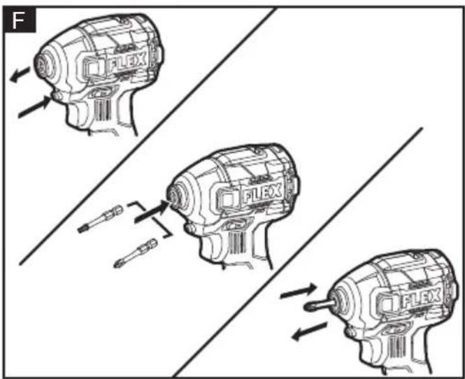
natural_image
Line drawing of a PLEX electric drill press with an arrow indicating motion (no text or symbols on the device itself)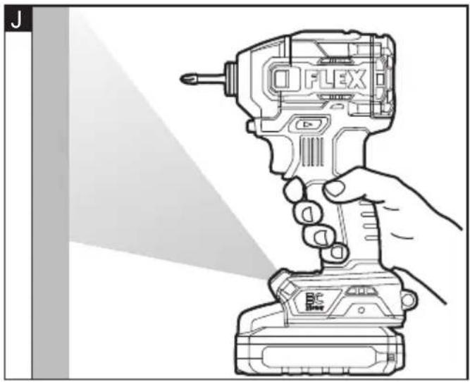
natural_image
Line drawing of a hand holding a compact O FLEX drill press with a flashlight, no text or symbols present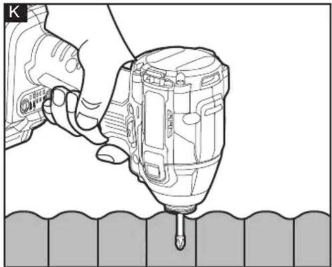
natural_image
Line drawing of a hand using a drill bit to press down a wall, no text or symbols present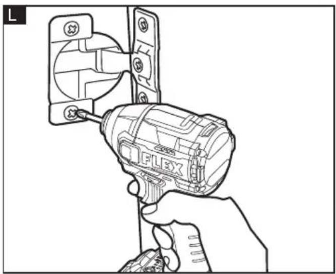
natural_image
Line drawing of a hand using a Flex tool to adjust or install a wall socket (no text or symbols present)Symbols used in this manual

WARNING!
Denotes impending danger. Non-observance of this warning may result in death or extremely severe injuries.

CAUTION!
Denotes a possibly dangerous situation. Non-observance of this warning may result in slight injury or damage to property.

NOTE
Denotes application tips and important information.
Symbols on the power tool
V
Volts
/min Rotation rate

To reduce the risk of injury, read the operating instructions!

Disposal information for the old machine (see page 18)!
For your safety

WARNING!
Before using the power tool, please read the follow:
– these operating instructions,
- the "General safety instructions" on the handling of power tools in the enclosed booklet (leaflet-no.: 315.915),
– the currently valid site rules and the regulations for the prevention of accidents.
This power tool is state of the art and has been constructed in accordance with the acknowledged safety regulations.
Nevertheless, when in use, the power tool may be a danger to life and limb of the user or a third party, or the power tool or other property may be damaged.
The cordless impact driver may be used only
-asintended,
– in perfect working order.
Faults which impair safety must be repaired immediately.
Intended use
The cordless impact driver is intended
– for commercial use in industry and trade,
– for fastening and loosening of bolts, nuts and various threaded fasteners.
Safety instructions for impact driver

WARNING!
Read all safety warnings, instructions, illustrations and specifications provided with this power tool. Failure to follow all instructions listed below may result in electric shock, fire and/or serious injury. Save all warnings and instructions for future reference.
- Hold power tool by insulated gripping surfaces, when performing an operation where the fastener may contact hidden wiring or its own cord. Fasteners contacting a "live" wire may make exposed metal parts of the power tool "live" and could give the operator an electric shock.
Noise and vibration
The noise and vibration values have been determined in accordance with EN 62841.
The A evaluated noise level of the power tool is typically:
– Sound pressure level L_pA : 90 dB(A);
- Sound power level L_WA : 101 dB(A);
- Uncertainty: K = 3dB.
Total vibration value:
- Emission value a_h : 19.78 m/s
- Uncertainty: K = 1.5 m/s ^2

CAUTION!
The indicated measurements refer to new power tools. Daily use causes the noise and vibration values to change.

NOTE
The vibration emission level given in this information sheet has been measured in accordance with a measurement method standardised in EN 62841 and may be used to compare one tool with another.
It may be used for a preliminary assessment of exposure. The specified vibration emission
level represents the main applications of the tool.
However, if the tool is used for different applications, with different cutting accessories or poorly maintained, the vibration emission level may differ.
This may significantly increase the exposure level over the total working period.
To make an accurate estimation of the vibration exposure level, it is also necessary to take into account the times when the tool is switched off or running but not actually in use.
This may significantly decrease the exposure level over the total working period.
Identify additional safety measures to protect the operator from the effects of vibration such as: maintain the tool and the cutting accessories, keep the hands warm, organisation of work patterns.

CAUTION!
Wear ear defenders at a sound pressure above 85 dB(A).
Technical data
| Tool | ID 1/4"18.0-EC-HD | |
| Type Impact driver | ||
| Rated voltage Vdc | 18 | |
| No-load speed r.p | m 0-3700 | |
| Max. impact rate b | pm 4200 | |
| Max torque N 237 | ||
| Weight according to"EPTA Procedure 01/2003"(without battery) | kg 1.22 | |
| Battery | AP18.0/2.5 | AP18.0/5.0 |
| Weight of battery/kg | 0.4 0.7 | |
| Working Temperature | -10-40°C | |
| Storage Temperature | < 50°C | |
| Charging Temperature | 4~40°C |
| Charger CA 10.8/1 | 8.0, CA 18.0-LD |
Overview (see figure A)
The numbering of the product features refers to the illustration of the machine on the graphics page.
1 Hex chuck
2 Accessory install /release button
3 Variable-speed trigger switch
4 Torque and "T" mode control panel
5 LED light
6 Direction preselector switch (forward / center-lock / reverse)
7 Strap fixing
For attaching a wrist strap (not included) in order to reduce the chances of dropping your tool.
8 Bit bracket
9 Belt clip
10 Fastening screw
Operating instructions

WARNING!
Remove the battery before carrying out any work on the power tool.
Before switching on the power tool
Unpack the cordless impact driver and check that here are no missing or damaged parts.

NOTE
The batteries are not fully charged on delivery. Prior to initial operation, charge the batteries fully. Refer to the charger operating manual.
Inserting/replacing the battery
■ Press the charged battery into the power tool until it clicks into place (see figure B).
■ To remove, press the release button and pull out the battery (see figure C).

CAUTION!
When the device is not in use, protect the battery contacts. Loose metal parts may short circuit the contacts; explosion and fire hazard!
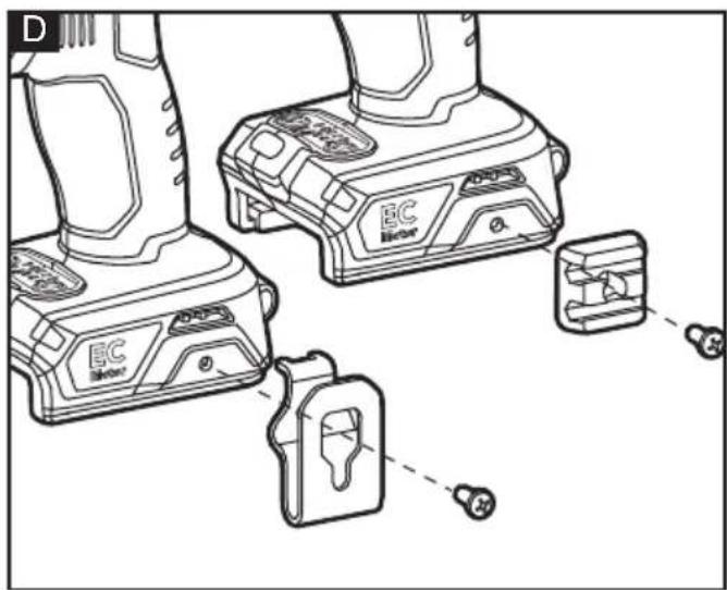
Removable belt clip and bit bracket
■ Remove the battery pack from the tool.
■ Align the hole of the belt clip 9 and bit bracket 8 with the threaded hole on the base of the tool (see figure D).
■ Insert the fastening screw 10 and securely tighten the screw with a screwdriver (not included).
Strap fixing
- Strap fixing is provided to attach a wrist strap (not included) in order to reduce the chances of dropping your tool. Wrap the strip around your hand when carrying the tool (see figure E).
Install and remove bits (see figure F)

CAUTION!
Before carrying out any work on the power tool, move the direction preselector switch 6 to the middle position.
■ Depress the accessory install/release button2, the locking sleeve will move forward (away from the tool).
■ Insert the bit as far as it will go into the chuck, and then release the accessory install/release button to lock the bit in place.
■ To remove the bit, depress the accessory install/release button2 to push the locking sleeve forward (away from the tool).
■ Pull the bit from the chuck and release the accessory install/release button, the locking sleeve will retract to original position.

NOTE
Use only bits with power grooves, other bits can be used with a universal bit holder that has power groove (not included). Do not use a bit that has a damaged shank.

WARNING!
The bit may be hot after prolonged use. Use protective gloves when removing the bit from the tool, or first allow the bit to cool down.
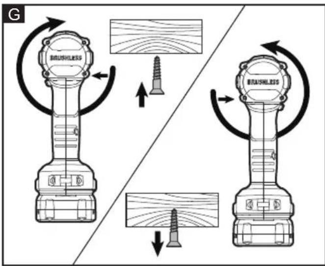
Direction preselection (see figure G)

CAUTION!
Change the direction of rotation only when the power tool is stopped.
Move the direction preselector switch 6 to the required position:
■ Position the direction preselector switch to the far left of the tool to drive screws in or tighten bolts/nuts
■ Position the direction preselector switch to the far right of the tool to remove screws or loosen bolts/nuts.
■ Position the direction preselector switch in the "OFF" (center-lock) position to help reduce the possibility of accidental starting when not in use.

NOTE
The impact driver will not run unless the direction-of-rotation selector is engaged fully to the left or to the right.

WARNING!
Battery tools are always in operating condition. Therefore, the direction preselector switch should always be locked in the center position when the tool is not in use or when carrying it at your side.
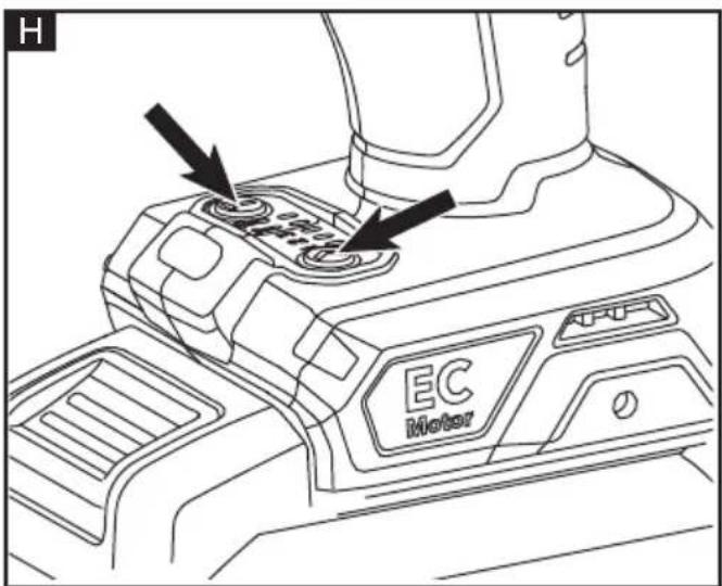
Mode selection (see figure H) CAUTION!
Your tool is equipped with a speed-control panel 4. It consists of a drive-control button, "T" button (a mode for use with self-tapping screws in sheet metal), and 5 working modes. Use the drive-control button or "T" button to select one of these 5 modes as appropriate for the application.
The drive-control button is used to select among three modes to adjust the torque, rotation-speed (RPM), and impact-speed (IPM) setting for an application. The modes 1, 2, and 3 are the only modes where the speed is controlled by the variable-speed trigger switch.
To select the drive control mode:
- First, check the active mode. Either depress and release the trigger switch or press the drive control button or "T" button directly without touching the trigger switch. The LED indicator below the mode number will illuminate to indicate the active mode setting.
■ Press the drive-control button briefly (less than 0.5 second) to cycle through the 3 modes. Each press changes one torque level. See more details in the chart below.
To select the "T" mode:
■ Two methods are available to check the current T mode: Either depress and release the trigger switch or press the drive-control button or the "T" button directly without touching the trigger switch.
The LED indicator below the mode number will illuminate to indicate the current mode setting.
Press the "T" button briefly (less than 0.5 seconds) to cycle between T1 and T2 modes. Each press changes one mode. See more details in chart below:
| it indicatordisplayed on panel | Woking mode | Purpose Example of application | |
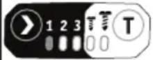 | 1 | Tightening when a good finishing is needed | Tightening screws into sensitive boards, such as plaster boards |
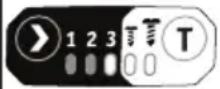 | 2 | Tightening with less force and speed than mode 3 (easier to control than mode 3) | Driving screws into hard materials as well as tightening bolts |
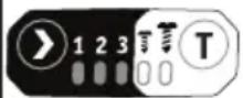 | 3 | Tightening with the maximum force and speed | Driving long screws into hard materials, as well as tightening bigger bolts than mode 2 |
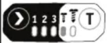 | TI | Driving self-tapping screws into sheet metal with good finish | Recommended type: #4.2x13 mm |
| Recommended type: #4.8x25 mm | |||
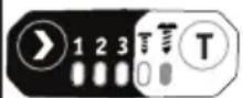 | T2 | Driving self-tapping screw into thick metal with good finish (handing tougher work compare to T1 mode) | Recommended type: #5,5x38 mm or 6.3x60 mm |

NOTE
The variety of wood density and metal material may affect the final outcome. The user should select appropriate mode based on the application.
WARNING!
Do not change the working mode while the tool is running. Sudden change of torque may cause the loss of control causing possible injury or damage to the tool or workpiece.
NOTE
The LED indicator will turn off approximately 1min after the trigger switch is released.
NOTE
When the tool is next turned on, the working mode will revert to the previous setting.
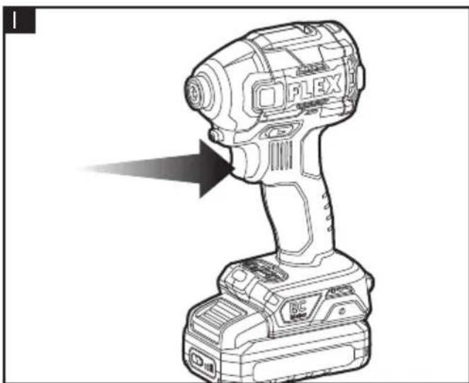
Switching on the power tool (see figure I)
■ To switch the power tool on:
Press the trigger switch 3.
The variable-speed trigger switch delivers higher speed with increased trigger pressure and lower speed with decreased trigger pressure.
In T1 and T2 modes pressing the trigger switch will deliver the highest rotation speed within current mode regardless of the pressure exerted on the switch.
■ To switch the power tool off:
Release the trigger switch.
LED light (see figure J)
■ The LED light will automatically turn on with a slight squeeze on the variable-speed trigger switch before the tool starts running and will turn off approximately 10 seconds after the variable speed trigger switch is released.
■ The LED light will rapidly flash when the tool and/or battery pack becomes overloaded or too hot, and the internal sensors will turn the tool off. Rest the tool for a while or place the tool and battery pack separately under air flow to cool them.
■ The LED light will flash more slowly to indicate that the battery is at low-battery capacity. Recharge the battery pack.
■ If the LED fails to light up when you switch on the tool, or it turns off suddenly during your operation, it may be caused by the internal communication error. Please contact customer service or an authorized service center for assistance.
Tighten and loosen screws, nuts and bolts (see figure K & L)
Select the T1 or T2 mode as necessary, based on your application. For more details see related section: Mode Selection. For mode 1, 2, or 3: variable-speed control must be used with caution for driving nuts and bolts using socket-set attachments. The best technique is to start slowly, increase speed as the nut or bolt runs down, and then set the nut or bolt snugly by slowing the tool to a stop. If this procedure is not followed, the tool will have a tendency to torque or twist in your hand when the nut or bolt seats.
It is advisable to perform a trial run on a scrap material to determine the best mode selection.
■ Install a suitable bit.
■ Apply just enough pressure to keep the bit engaged on the screw or nut.
■ For mode 1, 2, or 3, apply minimal pressure to the variable-speed trigger switch initially. Increase the speed only when full control can be maintained.
NOTICE:
■ Always use the correct type and size of bit for your application.
■ When turning in a screw at/near the crosscut end or an edge of wood, pre-drill a hole in order to avoid cracking of the wood.
■ When screw driving in hard wood, one should pre-drill a pilot hole.
WARNING!
Do not over-tighten, as the force of the impact driver can break the fastener. Keep the impact driver at a right angle to the fastener to avoid damaging the fastener head.
Maintenance and care

WARNING!
Remove the battery before carrying out any work on the power tool.
Cleaning
■ Clean the power tool and grille in front of the vent slots regularly. Frequency of cleaning is dependent on the material and duration of use.
■ Regularly blow out the housing interior and motor with dry compressed air.
Spare parts and accessories
For other accessories, in particular tools and polishing aids, see the manufacturer's catalogues.
Exploded drawings and spare-part lists can be found on our homepage:
www.flex-tools.com
Disposal information

WARNING!
Render redundant power tools unusable:
- mains operated power tool by removing the power cord,
- battery operated power tool by removing the battery.

EU countries only
Do not throw electric power tools into the household waste!
In accordance with the European Directive 2012/19/EU on Waste Electrical and Electronic Equipment and transposition into national law used electric power tools must be collected separately and recycled in an environmentally friendly manner.

Raw material recovery instead of waste disposal.
Device, accessories and packaging should be recycled in an environmentally friendly manner. Plastic parts are identified for recycling according to material type.

WARNING!
Do not throw batteries into the household waste, fire or water. Do not open used batteries.
EU countries only:
In accordance with Directive 2006/66/EC defective or used batteries must be recycled.

NOTE
Please ask your dealer about disposal options!
CE-Declaration of conformity
We declare on our sole responsibility that the product described in "Technical specifications" conforms to the following standards or normative documents: EN 62841 in accordance with the regulations of the directives 2014/30/EU, 2006/42/EC, 2011/65/EU. Responsible for technical documents: FLEX-Elektrowerkzeuge GmbH, R & D Bahnhofstrasse 15, D-71711 Steinheim/Murr
Peter Lameli Klaus Peter Weinper Technical Head Head of Quality Department
Exemption from liability
The manufacturer and his representative are not liable for any damage and lost profit due to interruption in business caused by the product or by an unusable product. The manufacturer and his representative are not liable for any damage which was caused by improper use of the product or by use of the product with products from other manufacturers.

Declaration of Conformity
We as the manufacturer: FLEX Elektrowerkzeuge GmbH, Business address: Bahnhofstr. 15, 71711 Steinheim, Germany declare under our sole responsibility, that the product(s) described under „Technical specifications“ fulfills all the relevant provisions of The Supply of Machinery (Safety) Regulations S.I. 2008/1597 and also fulfills all the relevant provisions of the following UK Regulations: Electromagnetic Compatibility Regulations S.I. 2016/1091, The Restriction of the Use of Certain Hazardous Substances in Electrical and Electronic Equipment Regulations S.I. 2012/3032 and are manufactured in accordance with the following designated Standards: BS EN 62841-1:2015, BS EN 62841-2-2:2014 BS EN 55014-1:2017, BS EN 55014-2:2015 Place of declaration: Steinheim, Germany. Responsible person: Peter Lameli, Technical Director - FLEX-Elektrowerkzeuge GmbH Contact details for Great Britain: FLEX Power Tools Limited, Unit 8 Anglo Office Park, Lincoln Road, HP 12, 3RH Buckinghamshire, United Kingdom.
Peter Lameli Klaus Peter Weinper Technical Head Head of Quality Department
12.05.2022
For attaching a wrist strap (not included) in order to reduce the chances of dropping your tool.
8 Bride
9 Clip de ceinture
10 Vis de fixation
- Usikkerhed: K = 3dB.
The impact driver will not run unless the direction-of-rotation selector is engaged fully to the left or to the right.

ADVARSEL!
Peter Lameli Klaus Peter Weinper Technical Head Head of Quality
Department (QD)
Peter Lameli Klaus Peter Weinper Technical Head Head of Quality Department
Technical Head Head of Quality
Department (QD)
Peter Lameli Klaus Peter Weinper Technical Head Head of Quality Department
Peter Lameli Klaus Peter Weinper Technical Head Head of Quality
Department (QD)
Peter Lameli Klaus Peter Weinper Technical Head Head of Quality Department
(QD)
Peter Lameli Klaus Peter Weinper Technical Head Head of Quality Department
(QD)



- Symbols used in this manual
- WARNING!
- CAUTION!
- NOTE
- Symbols on the power tool
- For your safety
- Intended use
- Safety instructions for impact driver
- Noise and vibration
- Overview (see figure A)
- Operating instructions
- Before switching on the power tool
- Inserting/replacing the battery
- Removable belt clip and bit bracket
- Strap fixing
- Install and remove bits (see figure F)
- Direction preselection (see figure G)
- Mode selection (see figure H) CAUTION!
- To select the drive control mode:
- To select the "T" mode:
- Switching on the power tool (see figure I)
- LED light (see figure J)
- Tighten and loosen screws, nuts and bolts (see figure K & L)
- NOTICE:
- Maintenance and care
- Cleaning
- Spare parts and accessories
- Disposal information
- Raw material recovery instead of waste disposal.
- CE-Declaration of conformity
- Exemption from liability
- Declaration of Conformity
- Bride
- Clip de ceinture
- Vis de fixation
- ADVARSEL!
Brand : Flex
Model : ID 1/4" 18.0-EC HD
Category : Drill