59513 - Air Conditioning Goobay - Free user manual and instructions
Find the device manual for free 59513 Goobay in PDF.

| Product type | Monobloc portable air conditioner (single duct) |
| Brand | Goobay |
| Model | 59513 |
| Dimensions (W × D × H) | 41.6 × 33.0 × 67.1 cm |
| Net weight | 24 kg |
| Power supply | 220-240 V ~, 50 Hz |
| Power consumption (cooling) | 950 W |
| Cooling capacity | 2.6 kW (9000 BTU/h) |
| Maximum recommended area | 20 m² |
| Operating modes | Cooling, dehumidification, ventilation, automatic |
| Special functions | Timer 1-24 h, Sleep mode, Child lock, Remote control |
| Refrigerant | R290 (propane), 185 g |
| Energy efficiency class | A |
| Sound power level | 65 dB(A) |
| Airflow rate | 350 m³/h |
| Dehumidification capacity | 1.1 L/h |
| Filter type | Washable air filter |
| Maintenance | Clean filter every 2 weeks, drain condensate if error code E4 |
| Package contents | Air conditioner, air exhaust hose, adapters, window insert, window cover, Velcro strip, remote control, CR2025 battery, user manual |
| Safety | Child lock, auto shut-off when tank full, compressor protection |
Frequently Asked Questions - 59513 Goobay
User questions about 59513 Goobay
0 question about this device. Answer the ones you know or ask your own.
Ask a new question about this device
Download the instructions for your Air Conditioning in PDF format for free! Find your manual 59513 - Goobay and take your electronic device back in hand. On this page are published all the documents necessary for the use of your device. 59513 by Goobay.
USER MANUAL 59513 Goobay
natural_image
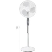
White portable air conditioner unit with a black control panel and 'goo bay' branding on the front (no visible text beyond branding)Lokales Klimagerät 9000 BTU/2600 Watt
Local air conditioner 9000 BTU/2600 Watt
Climatiseur local 9000 BTU/2600 Watt
natural_image
Pure diagram of a rectangular shape with an oval cutout and a horizontal line, no text or symbols present.natural_image
Simple line drawing of a cabinet with two downward arrows indicating vertical motion (no text or symbols)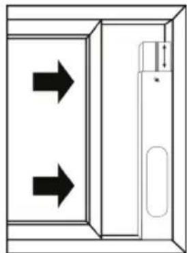
natural_image
Diagram of a door with two arrows indicating direction, no text or symbols presentnatural_image
Line drawing of a portable air conditioner next to a door opening (no text or symbols)natural_image
Technical line drawing of a vehicle air vent with ventilation grilles and a red arrow indicating direction (no text or symbols)12.3 Kondensatbehälter entleeren

1 Safety instructions ....22
2 Description and function 25
2.1 Product 25
2.2 Scope of delivery 25
2.3 Operating elements and parts 25
2.4 Specifications 26
3 Intended use....27
4 Unpacking the device 27
5 Transport....27
6 Assembly 28
7 Set up and installation ....29
7.1 Choosing the installation site....29
7.2 Laying the exhaust hose.... 29
7.3 Using the window insert.... 29
7.4 Using the window cover....30
8 Commissioning 31
9 Function buttons and status indicators ....31
10 Remote control 32
10.1 Activating the remote control.... 32
10.2 Explanation of the buttons....33
10.3 Changing the battery 33
11 Operation....33
11.1 Operating modes....33
11.2 Switching the air conditioner on and off.... 34
11.3 Selecting an operating mode.... 34
11.4 Setting the temperature....34
11.5 Setting the fan speed.... 34
11.6 Setting the timer function.... 34
11.7 Activating and deactivating the child lock 34
12 Maintenance and care ....35
12.1 Visual inspection of the inside of the unit for dirt 35
12.2 Cleaning the air filter....35
12.3 Emptying the condensate container 36
13 Storage 36
14 Faults and malfunctions....37
14.1 Safety device....37
14.2 Troubleshooting....37
14.3 Error codes.... 38
15 Disposal instructions....39
15.1 Product 39
15.2 Batteries 39
15.3 Packaging.... 39
16 EU Declaration of conformity 39
17 Symbols used ....40
1 Safety instructions
Information regarding the user manual
The user manual is part of the product and contains important information for correct use.
- Read the user manual completely and carefully before use.
The user manual must be available for uncertainties and passing the product. - Keep this user manual.
Warning levels
The following signal words are used in this user manual to indicate dangers when operating the air conditioner. Be sure to observe and follow all warnings to avoid risks!
DANGER!
Warnings against hazards that will result directly in serious injuries or death in case of non-observance.
WARNING! Warnings against hazards that may result in serious injuries or death in case of nonobservance.
CAUTION! Warnings against hazards that may result in injuries in case of non-observance.
NOTICE! Warnings against hazards that may result in material damage in case of non-observance.
Notes regarding the combustible refrigerant propane
The air conditioner contains propane (R290) as a refrigerant.
Propane is a colourless, odourless gas with minimal global warming potential that complies with European environmental regulations on refrigerants. Improper handling or unforeseen events can lead to accidents or damage that cause gas to leak from the air conditioner.
The danger of an incident with severe consequences occurring is very minimal with an
air conditioner of this size.
Propane in combination with air is highly combustible and can lead to an explosion.
- Only operate and store the air conditioner in rooms with an area of 10m^2 to avoid the danger of a concentration of flammable gas building up in the air.
If the cooling circuit is leaking, the escaping propane can ignite.
- If gas flows out of the air conditioner, call the fire brigade immediately! In this case, do not pull the mains plug and do not switch on or off any other electrical devices.
- Do not damage the cooling circuit or any of its components.
The gas is pressurised and can explode if heated.
- Only install and operate the unit in accordance with national regulations.
- Observe national gas regulations.
- Do not use any medium to accelerate the thawing process.
• The refrigerant levels outlined in the technical specifications (chapter 2.4) must not be exceeded.
Propane that is on fire cannot be extinguished with water.
- Extinguish burning propane with a fire extinguisher containing alcohol-resistant foam, carbon dioxide (CO₂) or extinguishing powder.
Propane is colourless, odourless and heavier than air. Leaking gas is very difficult to detect.
Propane is mildly toxic. Inhaling high concentrations of propane can lead to poisoning.
- Avoid the vicinity of leaking propane.
- Immediately seek fresh air if you have inhaled propane.
Propane removes a large amount of heat from its immediate vicinity as it leaks out from the air conditioner. Propane has the potential to burn the skin.
- If you come into direct contact with propane, thoroughly rinse the area of contact with cold to lukewarm water.
• If you receive burns or experience nausea due to propane, seek immediate medical attention.

Risk of electric shock
The product may cause an electric shock if it comes into contact with water.
- Do not use the product with wet hands.
- Do not use the product in the immediate vicinity of water, for example, bathtubs, sinks or swimming pools.
- Do not expose the product to direct streams of water.
Rain splashing on the product may cause an electric shock.
- Do not place the product near an open window.
Voltage-free only with pulled plug.
- In case of emergency, after use and during a thunderstorm, pull the mains plug out of the socket directly at the plug housing.
Do not pull the mains plug when propane is leaking from the air conditioner.
- Do not open the housing.
- Do not modify product and accessories.
- Do not short-circuit connectors and circuits.
- Do not insert any objects or fingers into ventilation slots or connection sockets!
The unit must not be operated with a defective mains cable!
- Check regularly that the appliance cable is still intact.
- Only use the unit with the mains cable unwound.
- Do not use the product if the cable is damaged.
• Always hold the plug and not the cable when removing it from a socket. - Do not kink or stretch the mains cable.
- Use the product only with earthed sockets.
- Compare the technical data of the product, mains and peripheral devices. These must be identical.
A defective device may not be put into operation, but must be disconnected from mains and protected against further use.
- Use product, product parts and accessories only in perfect condition.
- In case of questions, defects, mechanical damage, trouble and other problems, non-recoverable by the documentation, contact your dealer or manufacturer.
- Do not repair defective products yourself, but contact the dealer or the manufacturer.
Risk of poisoning
- Do not drink the condensate.
Tripping hazard
- Mind placing cables in a way that they do not form obstacles and cannot be damaged.
Operation and storage conditions
- NEVER leave the product unattended while in operation.
- Do not cover the product.
- Keep all ventilation slots free.
- Make sure that the air inlet and air outlet are clear.
• Make sure that the inlet side is free of dirt. - Do not operate the product in dusty environments or in areas with inadequate ventilation.
- Do not operate the fan in the vicinity of explosive and/or flammable gases.
- Do not operate the product in an explosive environment.
- Do not place or operate the product near open flames, cooking appliances or devices that generate heat such as radiators or stoves.
- Keep the unit at least 1 metre away from televisions or radios to avoid electromagnetic interference.
- Place the product on a stable, level, dry and dust-free surface so that it cannot tip over during operation and the surface cannot be damaged by vibrations.
- Place the unit on a flat surface with a slope of less than 5^ .
- Make sure that the product stands securely.
The unit must not stand on the mains cable to prevent it from tipping over during operation.
- Avoid stresses such as heat and cold, moisture and direct sunlight, microwaves, vibrations and mechanical pressure.
- Switch off the unit and disconnect it from the mains when it is not in use, when cleaning it or when it malfunctions.
- Store the product in a cool and dry place.
-
Do not sit on the product.
-
Do not place any objects on the product.
- Observe the minimum distances to walls and objects when installing.
- Only transport the unit if the condensate container is empty.
- Allow the air conditioner to stand for at least 12 hours after each transport to allow the refrigerant to collect in the compressor.
Target group information
Service work such as maintenance, care and troubleshooting may only be carried out in accordance with the manufacturer's instructions.
- Observe the information in chap. 12 „Maintenance and care“.
- Observe the information in chap. 14 „Faults and malfunctions“.
The entire refrigerant circuit is a hermetically sealed system that does not require maintenance and may only be repaired by companies that specialise in refrigerant and air conditioning technology.
Maintenance work that requires opening the housing may only be performed by companies that specialise in refrigerant and air conditioning technology.
The unit may only be repaired or serviced by an authorised specialist.
Any person that works on a refrigerant circuit must be able to provide proof of a certificate of competency issued by an accredited authority.
Not recommended for children and people with physical and/or mentally limited capabilities.
- Secure the product against accidental use.
- Secure packaging, small parts and insulation against accidental use.
Battery hazards
The remote control is equipped with a lithium button cell. It can be replaced.
- Keep batteries out of the reach of children.
If swallowed, there is a risk of severe internal burns or even death. Seek immediate medical attention if you believe someone may have swallowed or otherwise ingested the battery.
- Never use batteries when they are dented, leaked or damaged.
- Remove leaked, deformed or corroded batteries from the product and dispose them by appropriate protectives.
If a battery has leaked, avoid contact with skin, eyes and mucous membranes. If necessary, rinse affected areas with water and seek medical attention immediately.
- Do not deform, burn or disassemble batteries and never puncture them with a sharp object.
Extreme heat can lead to explosion and/or leakage of corrosive liquid. Mechanical damage can cause gaseous substances to escape, which can be highly irritating, flammable or toxic.
- Do not short-circuit batteries or immerse them in liquids.
There is a risk of explosion, fire, heat, smoke and/or gas development.
- If the battery is accidentally dropped into water, remove it immediately. Place the battery in a safe, open area and stay away until it is completely dry. Do not reuse the dried battery, but dispose of it as indicated in chapter 15.2.
2 Description and function
2.1 Product
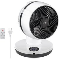
The product is a single duct air conditioner (local air conditioner) used for cooling, circulating and dehumidifying room air. The air conditioner is mobile and can be conveniently transported and used in different rooms.
The air conditioner can be controlled via a control panel or remote control and has a timer function.
2.2 Scope of delivery
-Local air conditioner (9000 BTU/2600 Watt)
-Exhaust hose
-Hose adapter
-Window insert
-Adapter for window insert
-Fixing screw
-Fixing nut
-Washer
-Window cover
-Velcro tape
-Remote control
-1x lithium button cell (CR2025)
-User manual
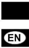
2.3 Operating elements and parts
1 Air outlet with cover
2 Signal receiver
3 Wheels
4 Control panel
5 Transport handle
6 Mains cable with winder
7 Air inlet with air filter
8 Upper outlet for condensate with plug
9 Air outlet for exhaust air
10 Lower outlet for condensate with plug
11 Remote control
12 Battery compartment
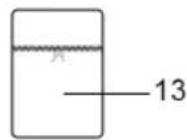
13 Window cover
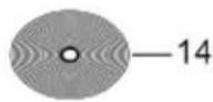
14 Velcro tape
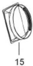
15 Hose adapter
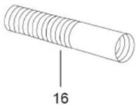
16 Exhaust hose
17 Adapter for window insert
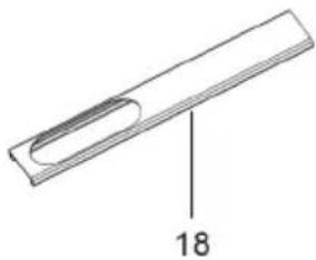
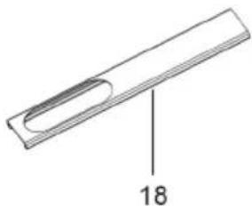
18 Window insert
19 Fixing nut
20 Washer
21 Fixing screw
2.4 Specifications
| Article number 59513 | |
| Air conditioner | |
| Model number FDP26-1080R5 | |
| Cooling capacity 2.6 kW / 9000 BTU | |
| Rated voltage / frequency 220-240 V | ~ / 50 Hz |
| Cooling input power 950 W / 4.3 A | |
| Pressure (outlet side) 2.5 MPa | |
| Pressure (inlet side) 1.2 MPa | |
| Sound pressure level L_PA | 54 dB(A) |
| Sound power level L_WA | 65 dB(A) |
| Protection class | I |
| Protection level IPX0 | |
| Fuse 250 V | ~ , 3.15 A, T or F |
| Rated capacity for cooling ( P_rated for cooling) 2.6 kW | |
| Rated power input for cooling ( P_EER ) 1.0 kW | |
| Rated energy efficiency ratio (EER _rated ) 2.8 | |
| Power consumption in standby mode ( P_SB ) 0.4 W | |
| Electricity consumption of single duct appliances for cooling ( Q_SD ) | 1.0 kWh/h |
| Global warming potential (GWP) 3 kg CO | 2 eq. |
| Energy efficiency class | A |
| Dehumidification capacity | 1.1 l/h |
| Air flow volume | 350 m3/h |
| Area of use / room size | 10 - 20 m2 |
| Cable length (incl. plug) | 1.8 m |
| Dimensions | 41.6 x 33 x 67.1 cm |
| Weight | 24 kg |
| Operating temperature | 15 °C ~ 43 °C |
| Max. room humidity | 80 % |
| Min. distance to walls and objects | 60 cm |
| Refrigerant | |
| Type | Propane (R290) |
| Fill level | 185 g |
| Exhaust hose | |
| Dimensions (∅ x Length) | 15.5 x 31.5 ~ 200 cm |
| Weight | Colour | 520 g | white |
| Window insert | |
| Dimensions | Length: 62 - 115 cmWidth: 11 cmHeight: 2 cm |
| Weight | Colour | 507 g | grey |
| Window cover | |
| Dimensions | 400 x 38,5 cm |
| Weight | Colour | 155 g | white |
| Velcro tape | |
| Width | Length 2.6 cm | 8 m | |
| Weight | Colour 90 g | white | |
| Remote control | |
| Type Infrared | |
| Input voltage 3.0 V | --- |
| Dimensions | Weight 40 x 86 x 7 | 11 g | |
| Range 5 m | |
| Battery | |
| Type Lithium button cell (CR2025) | |
| Nominal voltage, Capacity 3.0 V | ---, 150 mAh |
| Weight 3 g | |
3 Intended use

This product is intended exclusively for private use and its intended purpose. This product is not intended for commercial use. We do not permit using the device in other ways like described in chapter „Description and Function“ or in the „Safety Instructions“. Use the product only in dry interior rooms. Not attending to these regulations and safety instructions might
cause fatal accidents, injuries, and damages to persons and property.
IPX0: This product is not protected against water.
4 Unpacking the device
NOTICE! Material damage!
- Be careful when unpacking so as not to damage the air conditioner and the cooling circuit!
- Open the carton.
- Remove the accessories and the air conditioner and set them down carefully.
- Check that the scope of delivery is complete and undamaged.
- Unwind the mains cable completely and make sure that it is not damaged. Contact the dealer or manufacturer if you notice any damage or missing accessories.
- Compare the technical data of the product, power supply and peripheral devices. These must be identical.
5 Transport
NOTICE! Material damage!
The air conditioner may be damaged if transported incorrectly.
- Do not tilt the air conditioner more than 35^ .
- Only roll the air conditioner on flat surfaces.
- Keep the original packaging for transport.
- Place the air conditioner with special care so as not to damage the housing.
The air conditioner has wheels (3) and can be rolled over small distances if the surface is level. On uneven surfaces, stairs or over long distances, the air conditioner must be carried by at least 2 people.
Note that there may be additional transport regulations for units with flammable refrigerant.
Before each transport
- Switch off the air conditioner and pull the mains cable out of the socket at the plug.
• Empty the condensate container.
During transport
- Grip the air conditioner only by the transport handles (5).
- Put on non-slip, sturdy gloves.
- Do not pull on the mains cable to move the air conditioner.
- When transporting with a vehicle: position the air conditioner so that it cannot slide or fall over.
After each transport
- Place the air conditioner in an upright position.
- Allow the air conditioner to stand for at least 12 hours before operating it so that the refrigerant can collect in the compressor. Otherwise, the compressor may be damaged!
6 Assembly
If you want to use the air conditioner in the operating modes cooling, dehumidification and automatic, the exhaust hose (16) must be fitted in order for the exhaust air to be discharged from the room. No exhaust air is produced in the operating mode ventilation.
Proceed as follows to fit the exhaust air hose to the air conditioner:
| 1. Pull the exhaust hose (16) apart at both endsPay particular attention that the fins at the beginning and end of the exhaust hose are fully unfolded. | |
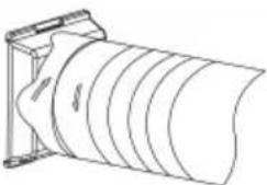 | 2. Attach the hose adapter (15) to one end of the exhaust hose. To do this, turn the hose adapter about 3 to 4 times counterclockwise onto the exhaust hose.The connection should be as airtight as possible. |
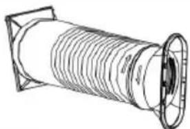 | 3. Attach the adapter for the window insert (17) to the other end of the exhaust hose. To do this, turn the adapter for the window insert about 3 to 4 times counterclockwise onto the exhaust air hose.The connection should be as airtight as possible. |
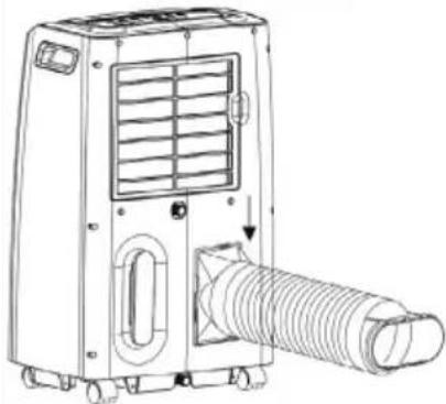 | 4. Attach the hose adapter to the air outlet for exhaust air (9) by pushing the hose adapter into the frame from above.The air conditioner is now assembled. |
7 Set up and installation
7.1 Choosing the installation site
DANGER! Fire hazard!
The air conditioner contains propane (R290) as a refrigerant. Propane in combination with air is highly combustible and can lead to an explosion.
- Only operate and store the air conditioner in rooms with an area of 10m^2 to avoid the danger of a concentration of flammable gas building up in the air.
- Do not operate the air conditioner in rooms where there are sources of ignition (e.g. naked flames, electric heaters, gas appliances that are switched on).
The choose the installation site for the air conditioner carefully. Consider the following aspects:
- The room in which the air conditioner is installed and used should not exceed 20 m ^2 .
There is a possibility of water dripping from the air conditioner (e.g. if an outlet for condensate is not properly closed).
○ A minimum distance of 60 cm from walls and objects must be maintained on all sides. - Position the air conditioner at least 1 m away from televisions or radios to avoid electromagnetic interference.
- Do not use the unit with an extension cord or over an adapter.
- Connect the mains cable with the mains plug directly to an earthed socket.
- If you use the air conditioner in the operating modes cooling, dehumidification or automatic, it must be possible to route the exhaust hose so that the exhaust air can flow to the outside.
Also observe the information in chapter 1 „Safety instructions“!
7.2 Laying the exhaust hose
The exhaust hose (16) is used to discharge the waste heat and humidity to the outside. There are various ways to install the exhaust hose.
For example, it can be clamped in a door or window. The end of the exhaust hose must then be secured so that it cannot slip.
If you route the exhaust air hose through a window, you should install the supplied window insert (18) or window cover (13) for efficient operation (see Chap. 7.3 or 7.4).
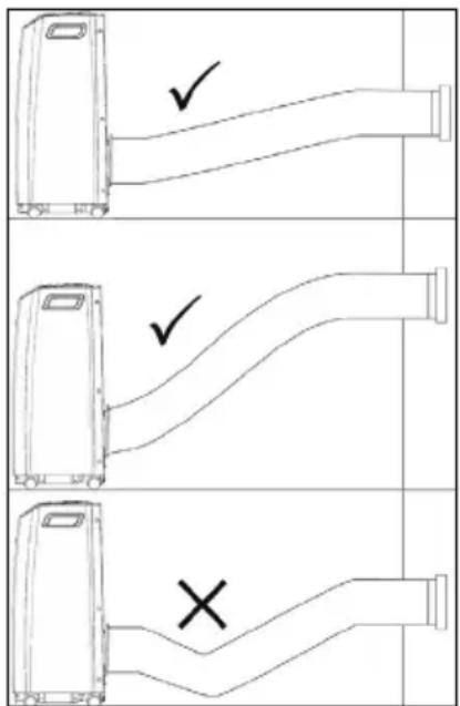
The hose should be laid as straight as possible or with an incline.
There should be no kinks in the exhaust hose. Kinks prevent the exhaust air from being discharged properly. Ejected air and condensate can accumulate and lead to malfunctions.
The exhaust hose should be as short as possible. The shorter the exhaust hose, the lower the energy consumption.
The supplied exhaust hose is matched to the unit. Do not replace or extend it with other hoses.
7.3 Using the window insert
The window insert (18) is intended for use with sliding windows. The window insert seals open spaces and keeps warm air and rain outside.
Assembling the window insert
The window insert (18) consists of two parts that slide against each other. One part has an opening for the exhaust air (left part) and the other part has a guide groove in the middle (right part). This allows you to freely adjust the width. The desired width is then fixed with the fixing nut (19), washer (20) and fixing screw (21).
- Slide the two parts of the window insert apart.
- Slide the washer onto the fixing screw.
- Insert the fixing screw with washer through the hole in the left part of the window insert. The fixing screw and the window insert should both lie horizontally in line.
- Slide the two parts of the window insert onto each other. Slide the fixing screw with washer into
the guide groove in the right part of the window insert.
-
Set the desired width.
-
Screw the fixing nut onto the fixing screw.
The window insert is now assembled and looks something like this:
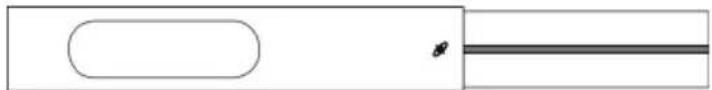
natural_image
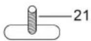
Pure diagram of a rectangular shape with an oval cutout and a horizontal line, no text or symbols present.Installing the window insert
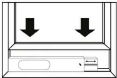
The window insert (18) can be used with both vertically and horizontally closing windows.
- Open the window.
- Insert the window insert into the window frame.
- Adjust the width of the window insert a second time if necessary.
CAUTION! Risk of crushing!
Fingers and limbs can be crushed.
- Do not hold fingers or limbs between the window, frame or window insert.
- Slide the window closed so that the window insert is wedged between the window and the frame.
The window insert is now installed. There should be as little free space as possible on the sides of the window insert.
- Clamp the end of the exhaust air hose with the window insert adapter (17) into the window insert.
The exhaust air from the air conditioner is now discharged to the outside and the warm air is kept outside.
natural_image
Simple line drawing of a cabinet with two downward arrows indicating opposing directions (no text or symbols)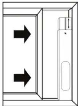
natural_image
Diagram of a door with two arrows indicating direction, no text or symbols present7.4 Using the window cover
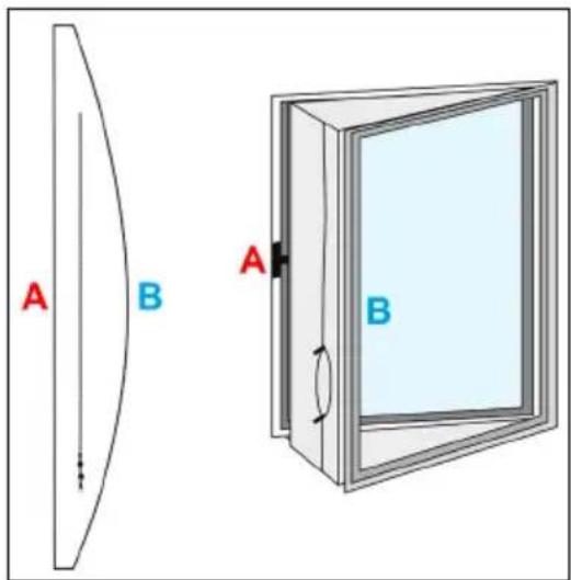
The window cover (13) is intended for use with casement windows. It seals open spaces and keeps warm air and rain outside. The window cover can be used universally for casement windows with a circumference of up to 400 cm.
The velcro tape (14) is needed to install the window cover.
Installing the window cover
- Open the window.
-
Lay the velcro tape along the window frame and along the opened window.
The velcro tape is self-adhesive and can be cut to size as required. -
Attach the window cover to the window frame and to the open window using the velcro tape.
The straight side of the window cover (A) is attached to the window frame.
The curved side of the window cover (B) is attached to the open window.
- Move the zip to the place where the exhaust hose is to be positioned.
The window cover is now installed.
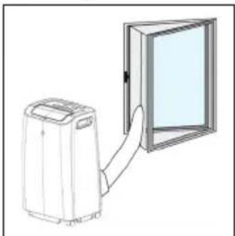
Passing the exhaust hose through the window cover

natural_image
Illustration of a portable air conditioner next to a door with a handle (no text or symbols)- Guide the exhaust hose (16) through the opening in the window cover.
- Secure the exhaust hose by closing the two zips. You can additionally use cable ties to reinforce the fastening (not included in the scope of delivery). The exhaust air from the air conditioner is now discharged to the outside and the warm air is kept outside.
8 Commissioning
NOTICE! Material damage!
There is refrigerant in the air conditioner. When the air conditioner is moved, the refrigerant is dispersed. If the air conditioner is switched on in this condition, it may cause damage or loss of cooling capacity.
- Allow the air conditioner to stand for at least 12 hours before operating it to allow the refrigerant to collect in the compressor.
-
Do not move the air conditioner during operation.
-
Plug the mains cable (6) into a free and easily accessible socket.
Make sure that the cable is laid in such a way that it does not obstruct anyone and is not damaged.
A signal tone sounds.
- Open the cover of the air outlet (1).
- Make sure that the air inlets and outlets are clear.
- Make sure that no objects (e.g. curtains) can be sucked in by the air inlets or obstruct the air flow.
- Make sure that the air filter (7) is correctly inserted and free of impurities.
The air conditioner can now be switched on and used.
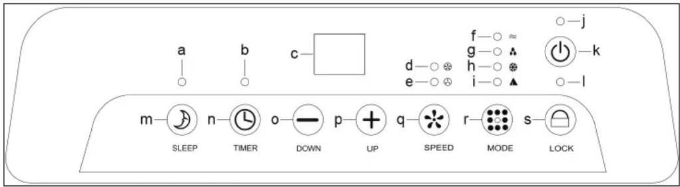
9 Function buttons and status indicators
The function buttons and status indicators are located on the control panel (4) of the air conditioner. The following illustration and table explain the function buttons and status indicators.
| Letter Designation Description | ||
| a | Status indicator SLEEP | The status indicator lights up green when the SLEEP mode is active |
| b | Status indicator TIMER | The status indicator flashes yellow while a timer is being set. The status indicator lights up yellow when a timer is active. |
| c Status display | The status display shows the temperature, timer duration and error codes. | |
| d | Status indicator for strong fan | The status indicator lights up yellow when the strong fan is active. |
| e | Status indicator for light fan | The status indicator lights up green when the light fan is active. |
| f | Status indicator Ventilation | The status indicator lights up yellow when the ventilation operating mode is active (see chapter 11.1). |
| g | Status indicator Dehumidification | The status indicator lights up green when the dehumidification operating mode is active (see chapter 11.1). |
| h | Status indicator Cooling | The status indicator lights up green when the cooling operating mode is active (see chapter 11.1). |
| i | Status indicator Automatic | The status indicator lights up green when the automatic operating mode is active (see chapter 11.1). |
| j | Status indicator ON/OFF | The status indicator lights up red when the air conditioner is swit-ched on. |
| k Button | ON/OFF | Press the button to switch the air conditioner on or off (see chap-ter 11.2). |
| l | Status indicator LOCK | The status indicator lights up green when the child lock is active. |
| m Button | SLEEP | Press the button to activate or deactivate the SLEEP mode.SLEEP mode can only be activated in cooling mode.In SLEEP mode, the light fan is set automatically. The set room temperature is increased by 1 °C after one hour, increased by 2 °C after 2 hours and the air conditioner switches itself off after 6 hours. |
| n Button | TIMER Press the key to set the timer function (see chapter 11.6). | |
| o Button | DOWN | Press the button to decrease the selected value (temperature, ti-mer). |
| p Button | UP | Press the button to increase the selected value (temperature, ti-mer). |
| q Button | SPEED Press the button to set the fan level (see chapter 11.5). | |
| r Button | MODE Press the button to set the operating mode (see chapter 11.3). | |
| s Button | LOCK | Press the button for about 5 seconds to activate or deactivate the child lock (see chapter 11.7). |
10 Remote control
10.1 Activating the remote control
- Pull the contact protector out of the battery compartment (12). The remote control is now activated.
10.2 Explanation of the buttons
Alternatively, you can also control the air conditioner via the remote control. The buttons on the remote control are explained below.

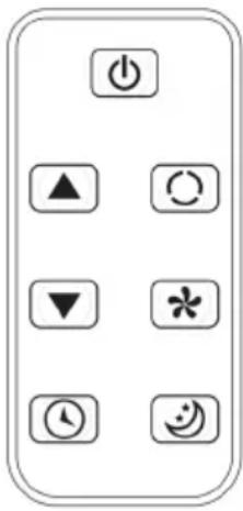 | Symbol Designation Description | |
| Button ON/OFF Press the button to switch the air conditioner on or off. | ||
| Button UP Press the button to increase the selected value (temperature, timer). | ||
| Button DOWN Press the button to decrease the selected value (temperature, timer). | ||
| Button TIMER Press the key to set the timer function. | ||
| Button MODE Press the button to set the operating mode. | ||
| Button SPEED Press the button to set the fan level. | ||
| Button SLEEP Press the button to activate or deactivate the SLEEP mode. | ||
10.3 Changing the battery
If necessary, replace the empty battery with a new one of the same type (See chapter 2.4)
- Open the battery compartment (12) by pushing the small lever to the side and then pulling out the battery compartment.
- Remove the empty battery.
- Place the new battery in the battery compartment with the positive pole facing upwards.
- Close the battery compartment again.
- Dispose of the empty battery properly.
See also chapter 15.2.
11 Operation
11.1 Operating modes
The air conditioner can be used in four operating modes. The operating modes ventilation, dehumidification, cooling and automatic are available.
The air conditioner has an internal memory. The temperature and fan speed settings in the operating modes are retained when you switch the air conditioner off and on again.
Ventilation
In ventilation mode, the room air is circulated. You can set the fan speed.
No cooling or dehumidification takes place. In this operating mode, the room temperature is not affected.
Dehumidification
In dehumidification mode, the relative humidity is reduced. The air conditioner automatically runs through different cycles. In this operating mode, air should not be able to escape from the room (e.g. through an open window).
The low fan speed is active and cannot be changed. In this operating mode, the room temperature is not affected.
Cooling
In the cooling operating mode, heat is extracted from the room air and the cooled air is fed back into the room. Part of the air, the extracted heat and any condensate are discharged outside via the exhaust hose. In this operating mode, air should be able to flow in from an adjacent room, for example through a door gap.
The fan speed and the desired room temperature can be set. In addition, the SLEEP mode can be activated.
Automatic
In the automatic operating mode, the air conditioner automatically switches between the ventilation and cooling operating modes to maintain a temperature of 24 °C .
At a room temperature ≥ 24 ^ C, the air conditioner switches to cooling mode.
At a room temperature < 24 °C, the air conditioner switches to ventilation mode.


11.2 Switching the air conditioner on and off
- Press the ON/OFF button (k) to switch on the air conditioner.
The status display (c) shows the room temperature and the air conditioner is in automatic mode. - Press the ON/OFF button (k) again to switch off the air conditioner.
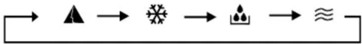
11.3 Selecting an operating mode
- Press the MODE button (r) to change the operating mode.
The operating modes are cycled through in this order:
flowchart
graph LR
    A --> B["▲"] --> C["✿"] --> D["♠"] --> E["≈"]
    E --> F["-"]
11.4 Setting the temperature
The temperature (set temperature) can be set in a range from 15 °C to 31 °C in steps of 1 °C . The air conditioner does not have a heating function. If the set temperature is higher than the room temperature, the air conditioner will not work.
The temperature can only be set in cooling mode.
- Press the UP button (p) to increase the value by 1 °C.
- Press the DOWN button (o) to decrease the value by 1 °C.
The set temperature flashes in the status display (c).
After 5 seconds, the status display shows the current room temperature again.
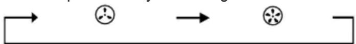
11.5 Setting the fan speed
Two fan speeds are available: light fan and strong fan.
- Press the SPEED button to change the fan speed.
The fan speeds are cycled through in this order:
flowchart
graph LR
    A --> B
    B --> C
    C --> D
    D --> E
11.6 Setting the timer function
The air conditioner has a timer function. The timer function can be set at intervals from one hour to 24 hours.
- Press the TIMER button (n) to activate the timer function.
The value for the timer flashes in the status display (c). The TIMER status indicator flashes yellow. - Press the UP button (p) to increase the value by 1 hour.
- Press the DOWN button (o) to decrease the value by 1 hour.
- When you have set the desired duration for the timer, wait about 5 seconds.
The status display switches to the current room temperature and the set timer is active. The TIMER status indicator lights up yellow. - Press the TIMER button (n) again to deactivate the timer function.
11.7 Activating and deactivating the child lock
The air conditioner has a child lock. When the child lock is active, the function of all buttons on the control panel and the remote control is locked.
- Press the LOCK button (s) for about 5 seconds to activate the child lock.
A signal tone sounds. The LOCK status indicator (I) lights up green.
- Press the LOCK button (s) again for about 5 seconds to deactivate the child lock.
12 Maintenance and care
DANGER! Risk of electric shock!
• Always disconnect the mains plug before cleaning.
- Do not use the product with wet hands.
- Make sure that no water or moisture gets inside the unit!
- Never insert a wet or damp air filter into the air conditioner!
- Do not expose the product to direct water jets.
NOTICE! Material damage!
- Make sure that no water comes into contact with electrical components!
- Only use a dry and soft cloth for cleaning.
- In case of heavy soiling, the cleaning cloth can be slightly moistened with water.
- Do not use detergents or chemicals.
- Be careful when cleaning to avoid scratches.
Maintenance intervals
| Maintenance task | before each use | if necessary | at least every 2 weeks | at least annually |
| Checking air inlets and outlets for dirt and clean if necessary. | x | x | ||
| Cleaning the housing x x | ||||
| Visual inspection of the inside of the unit for dirt | x | x | ||
| Cleaning the air filter x x | ||||
| Examining the air conditioner for damage | x | |||
| Emptying the condensate container | x |
12.1 Visual inspection of the inside of the unit for dirt
Look into all openings of the air conditioner. If necessary, use a torch to improve visibility. You can also remove the air filter (7) to better see the inside of the unit. If you see a thick layer of dust, have the air conditioner professionally cleaned by a specialist refrigeration and air conditioning company.
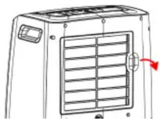
12.2 Cleaning the air filter
The air filter (7) must be cleaned regularly. Otherwise, malfunctions or reduced performance of the unit may occur. How often the air filter must be cleaned depends on the ambient conditions. If the air conditioner is used regularly, you need to clean the air filter approximately every 2 weeks or after about 100 hours of operation. In particularly dusty environments, the air filter should be cleaned more often.
Follow these steps to clean the air filter:
- Switch off the air conditioner and unplug the mains cable from the socket at the plug.
- Grasp the handle on the right side of the air filter.
- Pull the air filter towards you until it comes off.
- Clean the air filter with a dry, soft cloth or vacuum it carefully with a hoover.
4.1 If the air filter is very dirty, you can also use lukewarm water and a gentle detergent to clean it.
4.2 Allow the air filter to dry completely. Never insert a damp or wet air filter into the air conditioner!
-
Make sure that the air filter is neither worn nor damaged.
-
Reinstall the air filter.
You may have to press a little harder until you hear it click into place.
natural_image
Line drawing of a front-mounted air conditioner unit with ventilation grilles and a red arrow indicating airflow direction (no text or symbols)12.3 Emptying the condensate container
WARNING! Risk of poisoning!
The condensate is not of drinking water quality and can cause poisoning if consumed.
- Do not drink the condensate!
NOTICE! Material damage!
Water flowing out of the air conditioner can damage floors and furniture.
- Empty the condensate container in a suitable place (e.g. over a drain).
• Make sure that the outlets for condensate are properly closed.
Condensate is produced in the operating modes cooling and dehumidification. A large part of the condensate is discharged to the outside via the exhaust air. The remaining condensate collects in a container inside the unit. If the error code „E4“ appears in the status display (c), the condensate container must be emptied.
Proceed as follows to empty the condensate container:
- Switch off the air conditioner and disconnect the mains cable from the socket at the plug.
- Transport the air conditioner to a suitable place and take a collection container.
The collection container should be able to hold approx. 1.1 l. - Hold the collection container under the upper condensate outlet (8).
- Open the upper condensate outlet and allow the condensate to drain into the collection container.
- Close the upper condensate outlet with the plug.
- Empty the collection container.
- Hold the collection container under the lower condensate outlet (10).
7.1 Alternatively, you can position the air conditioner above a floor drain. - Open the lower condensate outlet and allow the condensate to drain into the collection container or into a floor drain.
- Close the lower condensate outlet with the plug.
The condensate container is now empty. The error code in the status display is no longer shown.
13 Storage
DANGER! Fire hazard!
The air conditioner contains propane (R290) as a refrigerant. Propane in combination with air is highly combustible and can lead to an explosion.
- Only operate and store the air conditioner in rooms with an area of 10m^2 to avoid the danger of a concentration of flammable gas building up in the air.
- Do not operate the air conditioner in rooms where there are sources of ignition (e.g. naked flames, electric heaters, gas appliances that are switched on).
CAUTION! Irritation of the respiratory tract!
Moisture in the air conditioner can lead to deposits and mould.
- If you do not use the air conditioner for the next seven days, store it according to the following instructions.
Perform the following operations before storing the air conditioner:
- Empty the condensation tank (see chapter 12.4).
- Clean the air filter (see chapter 12.3).
- Leave the air conditioner running in ventilation mode for 5 to 6 hours in a dry room to allow the inside of the air conditioner to dry.
- Remove the batteries from the remote control.
- Store the air conditioner in a suitable place. In particular, observe the instructions in the section "Operation and storage conditions" in chapter 1.

14 Faults and malfunctions
14.1 Safety device
The air conditioner is equipped with a safety device designed to protect the compressor. In case of frequent switching on and off or sudden disconnection from the mains, delays of up to 3 minutes may occur. This function is intentional and does not represent a malfunction.
The safety device also becomes active if the air conditioner is used outside the permissible operating temperature (see chapter 2.4).
14.2 Troubleshooting
In the following, some errors are listed that you can fix yourself. If you cannot find the error in the following table or if the suggested solutions do not work, contact the dealer or manufacturer or contact an authorised specialist company for refrigeration and air-conditioning technology.
| Error Cause Solution | ||
| The air conditioner cannot be switched on. | The safety device has been triggered. | → Wait 3 minutes and then try to switch on the air conditioner again. |
| The mains plug is not plugged in. | → Plug the mains plug into a wall socket. | |
| The batteries of the remote control are empty. | → Insert new batteries into the remote control. | |
| The built-in fuse has blown. | → Contact the dealer or manufacturer or contact an authorised specialist. | |
| The air conditioner operates only for a short time. | The set temperature is higher than or equal to the room temperature. | → Set a lower temperature. |
| The air outlet is blocked. → Remove the blockage from the air outlet. | ||
| The air conditioner operates in cooling mode, but the room temperature does not drop. | Warm air from outside is coming in through an open door or window. | → Close the door or window. If the exhaust hose is routed through the door or window, it must remain open. |
| Another appliance in the room is generating waste heat. | → Switch off the heat-generating appliance. | |
| The air filter is dirty. → Clean the air filter. | ||
| The air inlet or outlet is blocked. | → Remove the blockage. | |
| The set temperature is higher than the room temperature. | → Set a lower temperature. | |
| The air conditioner starts to freeze and goes into defrost mode. | → Wait for the defrosting process. Then you can continue to use the air conditioner as usual. | |
| The exhaust air hose is not routed correctly or is blocked. | → Follow the instructions in chapter 7.2. | |
| The room is larger than 20 m2. | → Use the air conditioner in rooms with a maximum size of 20 m2. | |
| Water is dripping from the air conditioner. | The air conditioner has been moved without emptying the condensate container. | → Empty the condensate container before moving the air conditioner. |
| The air conditioner is placed on an uneven surface. | → Move the air conditioner to a more suitable location (see chapter 7.1). | |
| The upper or lower condensate outlet is not properly closed. | → Close the outlet with the plug. | |
| The air conditioner suddenly switches off or stops working. | The set timer has expired. → | Switch the air conditioner on again. |
| The set temperature has been reached. | → Set a lower temperature or wait for the next cooling cycle. | |
| The condensate container is full and the error code "E4" appears in the status display. | → Empty the condensate container (see chapter 12.4). | |
| The air conditioner makes unusual noises or vibrates strongly. | The air conditioner is installed in an unsuitable location. | → Move the air conditioner to a more subtle location (see chapter 7.1). |
| The air conditioner makes bubbling noises. | Refrigerant is flowing through the cooling circuit. | → This does not represent a malfunction but is a normal operating noise. |
| The air conditioner has an unpleasant smell. | Deposits or mould have formed in the air conditioner. | → Have the air conditioner professionally cleaned by an authorised specialist company for refrigeration and air conditioning. |
14.3 Error codes
The following error codes may appear in the status display (c):
| Error code Cause Solution | ||
| E4 | The condensate container is full. | → Empty the condensate container (see chapter 12.4).If this error code occurs very frequently, contact the dealer or manufacturer or contact an authorised specialist company for refrigeration and air conditioning. |
| E2 | The sensor for determining the room temperature is disturbed or defective. | → Contact the dealer or manufacturer or contact an authorised specialist company for refrigeration and air-conditioning technology. |
| E3 | The sensor for monitoring the evaporator is disturbed or defective. | |
| E5 | The sensor for monitoring the compressor is disturbed or defective. | |


15 Disposal instructions
15.1 Product
According to the European WEEE directive, electrical and electronic equipment must not be disposed with consumers waste. Its components must be recycled or disposed apart from each other. Otherwise contaminative and hazardous substances can damage the health and pollute the environment.
As a consumer, you are committed by law to dispose electrical and electronic devices to the producer, the dealer, or public collecting points at the end of the devices lifetime for free. Particulars are regulated in national right. The symbol on the product, in the user manual, or at the packaging alludes to these terms. With this kind of waste separation, application, and waste disposal of used devices you achieve an important share to environmental protection.
WEEÈ No: 82898622
15.2 Batteries

(Rechargeable) batteries must not be disposed of with household waste. Their components have to be supplied separately to the recycling or disposal, because toxic and dangerous ingredients can harm the environment if not disposed of sustainably. As a consumer, you are obliged to return them at the end of their service lives to the manufacturer, the sales outlet or established
for this purpose, public collection points for free. Details regulates the respective country's law. The symbol on the product, the instruction manual and / or the packaging draws attention to those provisions. With this kind of material separation, recovery and disposal of waste (rechargeable) batteries you make an important contribution to protecting our environment.
D-34000-1998-0099
15.3 Packaging

Packaging can be disposed of free of charge at the suitable collection points – paper belongs in paper bins, plastics belong in yellow sacks and glass belongs in used glass bins. DE4535302615620
16 EU Declaration of conformity

With the CE sign, Goobay®, a registered trademark of the Wentronic GmbH, ensures that the product is conformed to the basic European standards and directives.
17 Symbols used
The following safety signs and symbols are used on the appliance and in the operating instructions.
| Warning; Flammable material ISO 7010 - W021 |  | |
| To indicate that the operating instructions should be considered when operating the device | ISO 7000 - 1641 |  |
| To indicate that the operator's manual or card should be read before continuing the operation | ISO 7000 - 0790 |  |
| To indicate that the technical manual shall be consulted ISO 7000 - 1659 |  | |
| The „GS“ test symbol stands for „Tested Safety“. Ready-to-use products and work equipment marked with the GS mark comply with the requirements of the German Product Safety Act (ProdSG). | - |  |
| Alternating current IEC 60417- 5032 |  | |
| Direct current IEC 60417- 5031 |  | |
| Recycling ISO 7001 - PI PF 066 |  | |
| Protective earth; protective ground (Class I equipment) IEC 60417- 5019 | [k2c4] | |
MODE D'EMPLOI
Table des matières
natural_image
Pure diagram of a rectangular object with an oval shape on the left and a horizontal line on the right (no text or symbols)natural_image
Simple line drawing of a cabinet with two downward arrows indicating vertical motion (no text or symbols)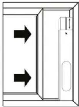
natural_image
Diagram of a door with two arrows indicating direction, no text or symbols presentnatural_image
Diagram of a portable air conditioner next to a door opening, showing airflow direction (no text or symbols)natural_image
Technical line drawing of a front-mounted air conditioner unit with ventilation grilles and a red arrow indicating direction (no text or symbols)natural_image
Simple diagram with a rounded rectangle and a horizontal line, no text or symbols presentnatural_image
Simple line drawing of a cabinet with two downward arrows indicating vertical motion (no text or symbols)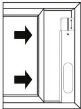
natural_image
Diagram of a door with two arrows indicating left and right motion directions (no text or symbols)natural_image
Diagram of a portable air conditioner next to a door with a handle (no text or symbols)natural_image
Line drawing of a vehicle hood with ventilation grilles and a red arrow indicating direction (no text or symbols)natural_image
Simple line drawing of a cylindrical object with threaded ends and a labeled dimension '16' (no text or symbols beyond the number)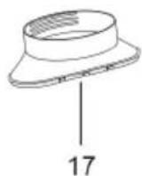
natural_image
Technical line drawing of a mechanical part with a labeled dimension (18), no text or symbols present.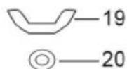
natural_image
Simple diagram with an oval shape and a horizontal line, no text or symbols presentnatural_image
Simple line drawing of a cabinet with two downward arrows indicating flow or movement (no text or symbols)
natural_image
Diagram of a door with two arrows indicating direction, no text or symbols presentnatural_image
Line drawing of a portable air conditioner next to a door opening (no text or symbols)natural_image
Line drawing of a vehicle front panel with ventilation grilles and a red arrow indicating direction (no text or symbols)- Introduzca el filtro de aire.
natural_image
Simple diagram with a rectangle containing an oval shape and a horizontal line with a small symbol (no text or labels)Vensterinzet installeren
natural_image
Simple line drawing of a cabinet with two downward arrows indicating vertical motion (no text or symbols)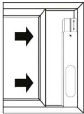
natural_image
Diagram of a door with two arrows indicating directions, no text or symbols presentnatural_image
Line drawing of a portable air conditioner next to a door with a handle (no text or symbols)natural_image
Line drawing of a vehicle front panel with ventilation grilles and a red arrow indicating direction (no text or symbols)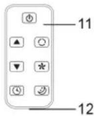
natural_image
Simple line drawing of a cylindrical object with threaded ends and a labeled dimension '16' (no text or symbols beyond the label)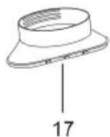
natural_image
Technical line drawing of a mechanical part with a slot and dimension label (no text or symbols beyond the number)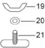
natural_image
Pure diagram of a rectangular object with an oval shape on the left and a horizontal line on the right (no text or symbols)FORSIGTIG! Fare for klemning!
natural_image
Simple line drawing of a cabinet with two downward arrows indicating opposing directions (no text or symbols)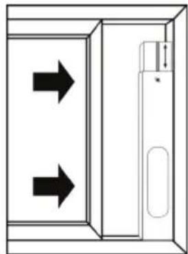
natural_image
Diagram of a door with two arrows indicating direction, no text or symbols presentnatural_image
Line drawing of a portable air conditioner next to a door opening (no text or symbols)natural_image
Line drawing of a front-mounted air vent with ventilation grilles and a red arrow indicating direction (no text or symbols)12.3 Tøm kondensatbeholder
ADVARSEL! Risiko for forgiftning!
natural_image
Pure diagram of a rectangular object with an oval shape on the left and a horizontal line on the right (no text or symbols)natural_image
Simple line drawing of a cabinet with two downward arrows indicating vertical motion (no text or symbols)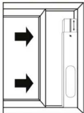
natural_image
Diagram of a door with two arrows indicating left and right directions, no text or symbols presentnatural_image
Line drawing of a portable air conditioner next to a door opening (no text or symbols)natural_image
Line drawing of a front-mounted air conditioner unit with ventilation grilles and a red arrow indicating airflow direction (no text or symbols)natural_image
Simple line drawing of a cylindrical object with a labeled dimension '16' (no text or symbols on the object itself)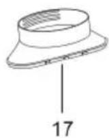

natural_image
Technical line drawing of a mechanical part with a labeled dimension (18), no text or symbols present.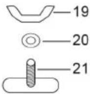
natural_image
Simple line drawing of a rectangular object with an oval shape on the left and a horizontal line with a small symbol on the right (no text or labels)natural_image
Simple line drawing of a cabinet with two downward arrows indicating vertical motion (no text or symbols)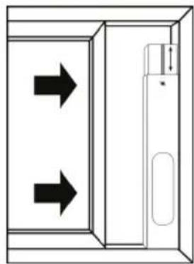
natural_image
Diagram of a door with two arrows indicating directions, no text or symbols present
natural_image
Line drawing of a portable air conditioner next to a door opening (no text or symbols)natural_image
Line drawing of a vehicle front panel with ventilation grilles and a red arrow indicating direction (no text or symbols)natural_image
Pure diagram of a rectangular object with an oval shape on the left and a horizontal line on the right (no text or symbols)natural_image
Simple line drawing of a cabinet with two downward arrows indicating downward motion (no text or symbols)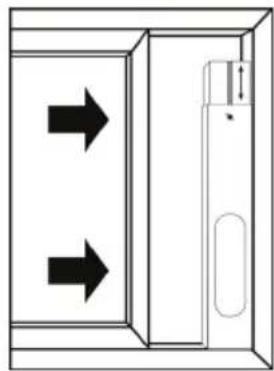
natural_image
Diagram of a door with two arrows indicating left and right directions, no text or symbols presentnatural_image
Line drawing of a portable air conditioner next to a door opening (no text or symbols)flowchart
graph LR
    A --> B
    B --> C
    C --> D
    D --> E
    E --> F
    F --> G
    G --> H
    H --> I
    I --> J
    J --> K
    K --> L
    L --> M
    M --> N
    N --> O
    O --> P
    P --> Q
    Q --> R
    R --> S
    S --> T
    T --> U
    U --> V
    V --> W
    W --> X
    X --> Y
    Y --> Z
natural_image
Line drawing of a vehicle front panel with ventilation grilles and a red arrow indicating direction (no text or symbols)© by Wentronic Deutschland
Hotline: +49 (0180) 5005882
Web: www.wentronic.com/content/mygoobay/
(0.14 € / minute from German landline)