59509 - Fan Goobay - Free user manual and instructions
Find the device manual for free 59509 Goobay in PDF.

| Product type | Pedestal fan |
| Brand | Goobay |
| Model | 59509 |
| Dimensions (L x W x H) | 39 x 125 x 39 cm |
| Rotor diameter | 43 cm |
| Adjustable height | 108 to 128 cm |
| Weight | 4550 g |
| Power supply | 220-240 V ~, 50 Hz |
| Rated power | 45 W |
| Standby power consumption | 0.4 W |
| Maximum air flow | 33.5 m³/min |
| Noise level | 58 dB(A) |
| Protection class | II |
| Protection rating | IPX0 (not protected against water) |
| Power cord length | 1.6 m |
| Functions | 3 speeds (L, M, H), modes Normal, Natural, Sleep, oscillation, timer up to 7.5 h |
| Remote control | Infrared, CR2025 battery included |
| Package contents | Base, rear and front grilles, rotor, support, screws, nuts, remote control, battery, user manual |
| Maintenance and cleaning | Unplug before cleaning, use a soft dry cloth, no detergents |
| Safety | Do not use near water, do not insert objects into the grille, keep away from children |
| Spare parts and repairability | Repairs only by a qualified professional |
| Usage | Indoor only, on a stable and level surface |
Frequently Asked Questions - 59509 Goobay
User questions about 59509 Goobay
0 question about this device. Answer the ones you know or ask your own.
Ask a new question about this device
Download the instructions for your Fan in PDF format for free! Find your manual 59509 - Goobay and take your electronic device back in hand. On this page are published all the documents necessary for the use of your device. 59509 by Goobay.
USER MANUAL 59509 Goobay
1 Safety instructions 10
2 Description and Function 11
2.1 Product 11
2.2 Scope of Delivery 11
2.3 Operating Elements 12
2.4 Specifications 12
3 Intended Use 13
4 Preparation 13
5Assembly 13
6 Function buttons and status indicators 14
7 Remote control 14
7.1 Activating the remote control 14
7.2 Explanation of the buttons 15
7.3 Changing the battery 15
8 Connection and operation. 15
8.1 Commissioning 15
8.2 Adjusting the height 15
8.3 Adjusting the tilt angle 15
9 Maintenance, Care, Storage and Transport. 16
10 Disposal instructions 16
10.1 Product 16
10.2 Batteries 16
10.3 Packaging 16
11 EU Declaration of conformity 16
12 Symbols used 16
1 Safety instructions
The user manual is part of the product and contains important information for correct use.
- Read the user manual completely and carefully before use.
The user manual must be available for uncertainties and passing the product. - Keep this user manual.
Risk of electric shock
When the product comes into contact with water, this may cause an electric shock.
- Do not use the product with wet hands.
- Do not use the product in the immediate vicinity of water, such as bathtubs, washbasins or pools.
Rain splashing on the product may cause an electric shock.
Do not place the product near an open window.
Voltage-free only with pulled plug.
In case of emergency, after use and during a thunderstorm, pull the mains plug out of the socket directly at the plug housing.
- Do not open the housing.
- Do not modify product and accessories.
- Do not short-circuit connectors and circuits.
- Check regularly that the appliance cable is still intact.
- Do not use the product if the cable is damaged.
A defective device may not be put into operation, but must be disconnected from mains and protected against further use.
- Use product, product parts and accessories only in perfect condition.
In case of questions, defects, mechanical damage, trouble and other problems non-recoverable by the documentation, contact your dealer or producer. - Do not repair defective products yourself, but contact the dealer or the manufacturer.
Risk of entry
Rotating parts can pull loose clothing and hair. This may result in injuries or damage to the device.
- Keep hair and loose clothing away from rotating parts.
- Make sure that the fan is not near curtains or other objects that could be pulled into the fan.
Risk of injury by moving product parts
There are moving parts behind the blade guard of the fan.
- Do not insert your finger or other objects through the blade guard.
This may result in injuries or damage to the device
- Only operate the device if the blade guard is closed and in good order.
- Do not use the device if the blade guard is damaged.
- Switch the device off and unplug the power cord before removing the blade guard.
Always pull the product by the plug, not the cable.
Tripping hazard
- Mind placing cables in a way that nobody will be disabled and the cable not be damaged.
Caused to different risk levels and hazard potentials some working steps only may be done by trained specialists.
Assembly, operation, maintenance, storage, transport and disposal may only be carried out by end users and users with basic mechanical and electrical knowledge.
- Disassembly, maintenance work and repairs may only be carried out by trained specialists.
Special safety measures, expertise and tools are required for this.
Not recommended for children and people with physical and/or mentally limited capabilities.
- Secure the product against accidental use.
- Secure packaging, small parts and insulation against accidental use.
Operation and storage conditions
- NEVER leave the product unattended while in operation.
- Do not cover the product.
- Keep fan slots and vents free.
- Do not operate the product in dusty environments or in areas with inadequate ventilation.
- Do not operate the fan in the vicinity of explosive and/or flammable gases.
- Do not place or operate the product near open flames, cooking appliances or devices that generate heat such as radiators or stoves.
- Place, install and transport product, product parts and accessories in a safe way.
- Place the product on a stable, level, dry and dust-free surface so that it cannot tip over during operation and the surface cannot be damaged by vibrations.
- Make sure that the product stands securely.
The fan must not stand on the mains cable so that it does not tip over during operation.
- Avoid stresses such as heat and cold, moisture and direct sunlight, microwaves, vibrations and mechanical pressure.
- Switch off the device and disconnect it from the mains when not in use, for cleaning or in the event of a malfunction.
Battery hazards
The remote control is equipped with a lithium button cell. It can be replaced.
- Keep batteries out of the reach of children.
If swallowed, there is a risk of severe internal burns or even death. Seek immediate medical attention if you believe someone may have swallowed or otherwise ingested the battery. - Never use batteries when they are dented, leaked or damaged.
- Remove leaked, deformed or corroded batteries from the product and dispose them by appropriate protectives.
If a battery has leaked, avoid contact with skin, eyes and mucous membranes. If necessary, rinse affected areas with water and soak

medical attention immediately.
- Do not deform, burn or disassemble batteries and never puncture them with a sharp object.
Extreme heat can lead to explosion and/or leakage of corrosive liquid. Mechanical damage can cause gaseous substances to escape, which can be highly irritating, flammable or toxic.
- Do not short-circuit batteries or immerse them in liquids.
There is a risk of explosion, fire, heat, smoke and/or gas development.
If the battery is accidentally dropped into water, remove it immediately. Place the battery in a safe, open area and stay away until it is completely dry. Do not reuse the dried battery, but dispose of it as indicated in chapter 10.2.
2 Description and Function
2.1 Product
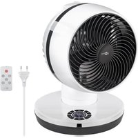
This product is a powerful pedestal fan that generates ventilation at 3 different levels and in different modes.
with remote control and timer
3 power levels: light, strong, turbo
2.2 Scope of Delivery
| No. | Designation | Pcs. | Description | No. | Designation | Pcs. | Description |
| 1 Base 1 | 8 F | Fixing nut 1 | |||||
| 2 | Rear blade guard | 1 | 9 | Fixing screw | 1 | ||
| 3 | Front blade guard with locking clips | 1 | 10 | Phillips screw∅ x L = 4.4 x 9.2 mm | 1 | ||
| 4 | Rotor | 1 | 11 | Screw nut∅ = 4.9 mm | 1 | ||
| 5 | Stand with function buttons, status indicators and motor block | 1 | 12 | Remote control | 1 | ||
| 6 | Base screw | 1 | 13 | Lithium button cell (CR2025) | 1 | - | |
| 7 | Washer 1 | 14 | User Manual | 1 | - |
2.3 Operating Elements
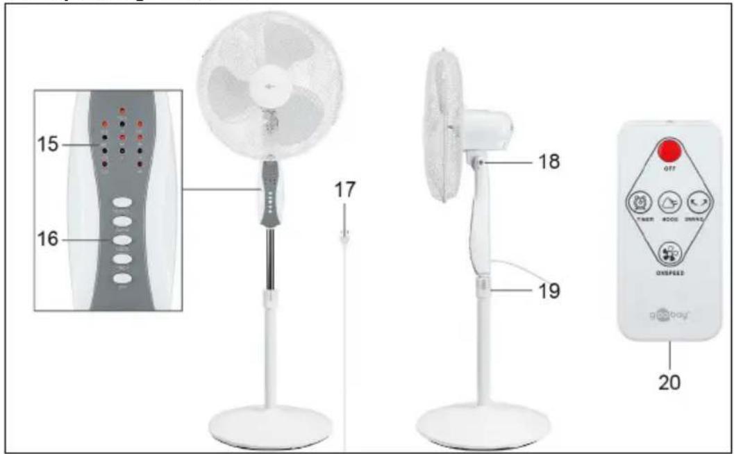
15 Status indicators
16 Function buttons
17 Mains cable with euro plug
18 Locking screw
19 Locking ring
20 Battery compartment
2.4 Specifications
| Article number 59509 | |
| Input 220-240 V | ~, 50 Hz |
| Rated power 45 W | |
| Fan power input (P) 38.1 W | |
| Standby power consumption (PSB) 0.4 W | |
| Max. fan flow rate (F) 33.5 m³/min | |
| Service value (SV) 0.9 (m³/min)/W | |
| Measurement standard for service value IEC 60879:2019 | |
| Max. air velocity (c) 2.0 m/s | |
| Fan sound power level (LWA) 58 dB(A) | |
| Protection level / Protection class | IPX0 / II☐ |
| Device connection Euro plug (Type C. CEE 7/16) | |
| Cable length (incl. plug) 1.6 m | |
| Dimensions W x H x D Ø | 39 x 125 x 39 cm 43 cm |
| Colour white-grey | |
| Weight 4550 g | |
| Remote control | |
| Type Infrared | |
| Input voltage | 3.0 V= |
| Dimensions | Weight | 40 x 86 x 7 | 11 g |
| Battery | |
| Typ | Lithium button cell (CR2025) |
| Nominal voltage, Capacity | 3.0 V=, 150-165 mAh |
| Weight | 3 g |
3 Intended Use

This product is intended exclusively for private use and its intended purpose. This product is not intended for commercial use. We do not permit using the device in other ways like described in chapter „Description and Function" or in the „Safety Instructions". Use the product only in dry interior rooms. Not attending to these regulations and safety instructions might cause fatal accidents, injuries, and damages to persons and property.
IPX0: This product is not protected against water.
4 Preparation
- Check the scope of delivery for completeness and integrity.
- Compare the specifications of product and power supply.
These must be identical.
5 Assembly
| 1. Insert the stand (5) into the base (1). | |
| 2. Place the stand and the base on their sides so that you can see the underside of the base. CAUTION! The base is heavy! ·Make sure that no fingers or limbs are wedged under the base! 3. Place the washer (7) over the hole in the centre of the base. 4. Insert the base screw (6) with the threaded side in the washer. 5. Tighten the base screw clockwise. The stand and the base are now firmly connected to each other. | |
| 6. Put the stand and the base back in place. 7. Slide the rear blade guard (2) on the axle of the motor block (5). Make sure that the hole at the edge of the rear blade guard is at the bottom. 8. Slide the fixing nut (8) onto the axle of the motor block. 9. Tighten the fixing nut clockwise. The rear blade guard is now fixed. | |
| 10. Push the rotor (4) onto the axle of the motor block. Make sure that the recesses on the back of the rotor are over the pins on the motor axle. 11. Slide the fixing screw (9) onto the axle of the motor block. 12. Tighten the fixing screw anticlockwise. The rotor is now fixed. | |
| 13. Hang the front blade guard (3) onto the rear blade guard with the hook. Make sure that the hole on the edge of the front blade guard faces the hole on the edge of the rear blade guard. 14. Slide the 4 locking clips, each located on the side of the front blade guard, over the frames of both blade guards. | |
| 15. Push the Phillips screw (10) through the holes of both blade guards. Fix the Phillips screw with the screw nut (11). Tighten the Phillips screw clockwise. The front blade guard is now fixed and the fan is ready for use. |
6 Function buttons and status indicators
The fan has 5 function buttons and 12 status indicators.
In the following table, the function buttons and the status indicators are explained.
| Function buttons | ||
| ON/SPEED SWING MODE TIMER OFF | Designation Description | |
| ON/SPEED | Press the button to switch on the fan. Press the button again to select the pow-er level. | |
| SWING | Press the button to switch the oscillation function on or off. When the oscillation function is switched on, the fan moves from side to side. | |
| MODE | Press the button to set the desired mode. You can choose between the modes NORMAL, NATURAL and SLEEP. | |
| TIMER | Press the button to activate the timer function. Press the button again to extend the duration of the timer function. You can set the timer function at half-hour intervals (0.5h, 1h, 1.5h, 2h, 2.5h, 3h, 3.5h, 4h, 4.5h, 5h, 5.5h, 6h, 6.5h, 7h, 7.5h). After the set time has elapsed, the fan switches itself off. To end the timer func- tion, press the button until all status displays for the timer (4H, 2H, 1H, 0.5H) have gone out. Alternatively, you can switch the fan off and on again to clear the set timer. | |
| OFF | Press the button to switch off the fan. The set power level and mode remain sa- ved and are active when you switch the fan on again. | |
| Status indicators | ||
| POW When the status indicator lights up, the fan is connected to the mains. | ||
| SLE | When the status indicator lights up, the SLEEP mode is active. The fan runs a programme of different fan speeds. | |
| NAT | When the status indicator lights up, the NATURAL mode is active. The fan is running a programme of different fan speeds. | |
| NOR | When the status indicator lights up, the NORMAL mode is active. The fan is ge- nerating a steady flow of air at the set power level. | |
| SW When the status indicator lights up, the oscillation function is activated. | ||
| H | When the status indicator lights up, the power level H is set. The fan generates strong airflow. | |
| M | When the status indicator lights up, the power level M is set. The fan generates medium-strong airflow. | |
| L | When the status indicator lights up, the power level L is set. The fan generates light airflow. | |
| 4H, 2H, 1H, 0.5H | If one of the status indicators lights up, the timer function is active for the spe- cified time. If several of the status indicators light up, timer function covers the sum of the active time intervals. | |
7 Remote control
7.1 Activating the remote control
- Pull the contact protector out of the battery compartment (20).
The remote control is now activated.


7.2 Explanation of the buttons
You can also control the fan via the remote control.
The following table describes the function of the buttons on the remote control.
| Designation Description | |
| OFF Press the button to switch off the fan. | |
| TIMER | Press the button to activate the timer function. Press the button again to extend the duration of the timer function. |
| MODE Press the button to set the desired mode. | |
| SWING Press the button to switch the oscillation function on or off. | |
| ON/SPEED | Press the button to switch on the fan. Press the button again to select the power level. |
7.3 Changing the battery
If necessary, replace the empty battery with a new one of the same type. See chapter 2.4.
- Open the battery compartment (20) by pushing the small lever to the side and then pulling out the battery compartment.
- Remove the empty battery.
- Place the new battery in the battery compartment with the positive pole facing upwards.
- Close the battery compartment again.
- Dispose of the empty battery properly. See also chapter 10.2.
8 Connection and operation
8.1 Commissioning
- Select a suitable location for the fan.
Pay particular attention to the requirements mentioned in chapter 1 „Safety instructions". - Connect the fan's mains cable (17) to a free and easily accessible socket.
- Turn the front of the fan in the direction you want to ventilate.
The fan is now ready for operation. - Set the power level, mode and timer function using the function buttons (16) or the remote control (12).
- Switch off the fan after use.
8.2 Adjusting the height
You can adjust the height of the fan from 108 to 128~cm
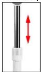
- Unplug the mains cable from the socket before adjusting the height.
- Turn the locking ring (19) anticlockwise to loosen it.
- Weight down the base with your foot and grasp the fan by the housing where the function buttons and status indicators are located.
- Slide the upper part of the fan up or down until you have set the desired height and hold the fan at this position.
- With the other hand, turn the locking ring clockwise to tighten it. The height of the fan is now adjusted.
8.3 Adjusting the tilt angle
You can also adjust the fan's tilt angle.
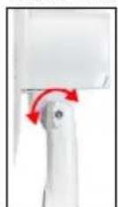
- Unplug the mains cable from the socket before adjusting the tilt angle.
- Turn the locking screw (18) anticlockwise to loosen it.
- Hold the fan by the blade guard and move it back and forth along the horizontal axis until you have set the desired tilt angle. Hold the fan in this position.
- With the other hand, turn the locking screw clockwise to tighten it. The fan's tilt angle is now adjusted.
9 Maintenance, Care, Storage and Transport
The product is maintenance-free.
NOTICE! Material damage
- Always disconnect the mains plug before cleaning.
- Only use a dry and soft cloth for cleaning.
- Do not use detergents or chemicals.
- Store the product out of the reach of children and in a dry and dust-protected environment when not in use.
- Remove batteries / rechargeable batteries when not in use.
- Regularly check the tightness of product/screws.
- Store cool and dry.
- Keep and use the original packaging for transport.
- Have maintenance, disassembly and repair work carried out by qualified personnel only.
10 Disposal instructions
10.1 Product
According to the European WEEE directive, electrical and electronic equipment must not be disposed with consumers waste. Its components must be recycled or disposed apart from each other. Otherwise contaminative and hazardous substances can damage the health and pollute the environment.
As a consumer, you are committed by law to dispose electrical and electronic devices to the producer, the dealer, or public collecting points at the end of the devices lifetime for free. Particulars are regulated in national right. The symbol on the product, in the user manual, or at the packaging alludes to these terms. With this kind of waste separation, application, and waste disposal of used devices you achieve an important share to environmental protection.
WEEE No: 82898622
10.2 Batteries
(Rechargeable) batteries must not be disposed of with household waste. Their components have to be supplied separately to the recycling or disposal, because toxic and dangerous ingredients can harm the environment if not disposed of sustainably.
As a consumer, you are obliged to return them at the end of their service lives to the manufacturer, the sales outlet or established for this purpose, public collection points for free. Details regulates the respective country's law. The symbol on the product, the instruction manual and / or the packaging draws attention to those provisions. With this kind of material separation, recovery and disposal of waste (rechargeable) batteries you make an important contribution to protecting our environment.
D-34000-1998-0099
10.3 Packaging
Packaging can be disposed of free of charge at the suitable collection points - paper belongs in paper bins, plastics belong in yellow sacks and glass belongs in used glass bins. DE4535302615620
11 EU Declaration of conformity
With the CE sign Goobay®, a registered trademark of the Wentronic GmbH ensures, that the product is conformed to the basic European standards and directives.
12 Symbols used
For indoor use only IEC 60417-5957
Alternating current IEC 60417-5032
Direct current IEC 60417-5031
Recycling ISO 7001 - PIPF 066
Class II equipment IEC 60417-5172
MODE D'EMPLOI
Table des matieres
© by Wentronic Deutschland
Hotline: +49 (0180) 5005882
Web: www.wentronic.com/content/mygoobay/
(0.14 € / minute from German landline)