FQ-SKS 235 - Sharpener For_Q - Free user manual and instructions
Find the device manual for free FQ-SKS 235 For_Q in PDF.


| Product type | Chain saw sharpener |
| Brand | For_Q |
| Model | FQ-SKS 235 |
| Rated voltage | 230 V~ / 50 Hz |
| Rated power | 235 W (S1) |
| No-load speed | 3000 /min |
| Grinding wheel outer diameter | max. 145 mm |
| Grinding wheel thickness | 3.2 mm |
| Grinding wheel bore | 22 mm |
| Types of sharpenable chains | 1/4 in, 0.325 in, 3/8 in, 0.404 in, 3/4 in |
| Top plate angle adjustment | +40° to -40° |
| Cutting angle adjustment | 90° to 40° |
| Net weight | 5.8 kg |
| Sound pressure level | 68.3 dB(A) (K=3 dB) |
| Sound power level | 81.3 dB(A) (K=3 dB) |
| Maximum vibration emissions | 3.05 m/s² (K=1.5 m/s²) |
| Protection class | I |
| Intended use | Sharpening of chain saw chains |
| Maintenance and cleaning | Clean with a soft damp cloth, lubricate moving parts, check the grinding wheel regularly |
| Safety | Wear safety glasses, hearing protection, dust mask, gloves; unplug before maintenance |
| Spare parts and repairability | Replaceable grinding wheel; repairs only by qualified personnel |
| Included supplies | Stand, head, handle, dressing stone, Allen keys 4 and 5 mm, cutting angle kit, table mounting kit, indicator |
Frequently Asked Questions - FQ-SKS 235 For_Q
User questions about FQ-SKS 235 For_Q
0 question about this device. Answer the ones you know or ask your own.
Ask a new question about this device
Download the instructions for your Sharpener in PDF format for free! Find your manual FQ-SKS 235 - For_Q and take your electronic device back in hand. On this page are published all the documents necessary for the use of your device. FQ-SKS 235 by For_Q.
USER MANUAL FQ-SKS 235 For_Q
text_image
DEPTH GUAGE .025 IN 8 3/8 1/4 3/8 3/8 3/8 3/25 404natural_image
Two identical mechanical flange components with bolt holes and central bore holes, shown side by side without any text or symbols.text_image
DEPTH GAUGE .030 IN 7/16 .404 3/8 .325 1/4 1/2 7/16 .404 3/8 GRINDING WHEELS FOR CHAINSnatural_image
Close-up of a hand holding a textured rectangular object against a mechanical component (no visible text or symbols)natural_image
Close-up of a mechanical device with labeled components and a central circular component (no readable text or symbols)natural_image
Close-up of a mechanical clamp or fixture component with a circular dial and directional arrows, no visible text or symbols.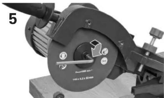
natural_image
Close-up of a mechanical clamp or fixture component with no visible text or symbols on the main body.natural_image
Close-up of a mechanical device with a circular component and control buttons, no visible text or symbols.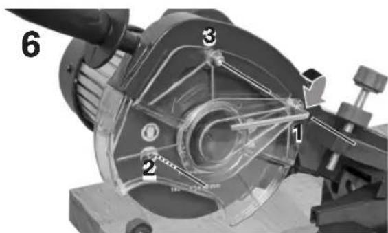
text_image
6 1 2 3natural_image
Two identical mechanical flange components with bolt holes and central bore holes, shown without any text or symbols.text_image
DEPTH GAUGE .030 IN 7/16 .404 3/8 .325 1/4 1/2 7/16 .404 3/8 GRINDING WHEELS FOR CHAINSnatural_image
Close-up of a hand inserting a textured rectangular object into a mechanical component (no visible text or symbols)natural_image
Close-up of a mechanical assembly with a circular component and adjustment knobs (no visible text or symbols)natural_image
Close-up of a mechanical clamp or fixture with a circular component and directional arrows, no readable text or symbols present.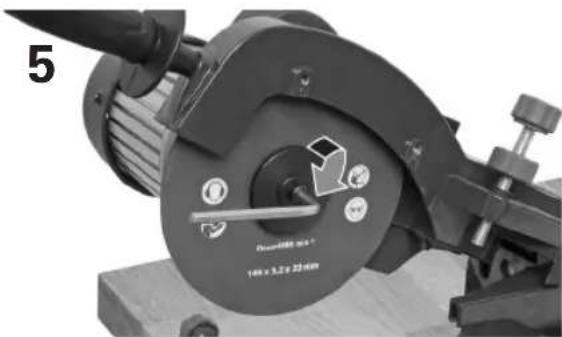
natural_image
Close-up of a mechanical clamp or fixture component with no visible text or symbolsnatural_image
Close-up of a mechanical device with circular components and a central dial, no visible text or symbols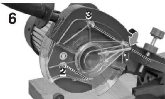
text_image
6 1 2 3Directive machines 2006/42/CE Directive RoHS 2011/65/UE Directive CEM 2014/30/UE
text_image
DEPTH GAUGE .030 IN 7/16 .404 3/8 .325 1/4 1/2 7/16 .404 3/8 GRINDING WHEELS FOR CHAINSnatural_image
Close-up of a hand inserting a textured rectangular object into a mechanical component (no visible text or symbols)natural_image
Close-up of a mechanical device with circular components and a central knob, labeled 'Round 400 mm' (no readable text beyond labels)natural_image
Close-up of a mechanical device with a circular component and directional arrows indicating motion (no readable text or symbols)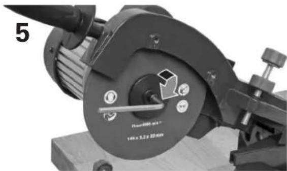
natural_image
Close-up of a mechanical device with a central knob and adjustment knob, labeled 'Round 1000 mm' (no readable text beyond labels)natural_image
Close-up of a mechanical device with circular components and a central dial, no visible text or symbols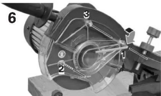
text_image
6 1 2 3text_image
DEPTH Gauge .025 IN 8 3/8 1/4 3/8 3/25 404natural_image
Two identical mechanical flange components with bolt holes and central bore holes, shown without any text or symbols.Machinevoorbereiding
text_image
DEPTH GAUGE .030 IN 7/16 .404 3/8 .325 1/4 1/2 7/16 .404 3/8 GRINDING WHEELS FOR CHAINSnatural_image
Close-up of a hand holding a textured rectangular object, next to a mechanical component (no visible text or symbols)natural_image
Close-up of a mechanical device with circular components and a central knob, no visible text or symbols.natural_image
Close-up of a mechanical device with a circular component and directional arrows indicating motion (no readable text or symbols)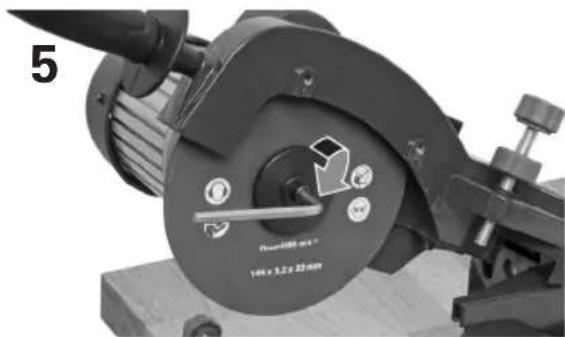
natural_image
Close-up of a mechanical device with a central knob and adjustment knob, labeled 'Round 1000 mm' (no readable text beyond labels)natural_image
Close-up of a mechanical device with circular components and a central dial, no visible text or symbols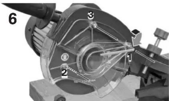
text_image
6 1 2 3text_image
DEPTH Gauge .025 IN 8 3/8 1/4 3/8 3/8 325 310 18 3/8text_image
DEPTH GAUGE .030 IN 7/16 .404 3/8 .325 1/4 1/2 7/16 .404 3/8 GRINDING WHEELS FOR CHAINSnatural_image
Close-up of a hand holding a textured rectangular object, partially visible in a mechanical component (no text or symbols)natural_image
Close-up of a mechanical device with labeled components and a central circular component (no readable text or symbols)natural_image
Close-up of a mechanical device with a circular component and directional arrows indicating motion (no readable text or symbols)
natural_image
Close-up of a mechanical clamp or fixture with a rotary knob and adjustment knob (no readable text or symbols)natural_image
Close-up of a mechanical device with circular components and a central dial, no visible text or symbols
text_image
6 1 2 3natural_image
Two identical mechanical flange components with bolt holes and central bore holes, shown without any text or symbols.Příprava přístroje
text_image
DEPTH GAUGE .030 IN 7/16 .404 3/8 .325 1/4 1/2 7/16 .404 3/8 .404 3/8 GRINDING WHEELS FOR CHAINSnatural_image
Close-up of a hand holding a textured rectangular object against a mechanical component (no visible text or symbols)natural_image
Close-up of a mechanical device with circular components and a central knob, no visible text or symbolsnatural_image
Close-up of a mechanical device with a circular component and directional arrows indicating motion (no readable text or symbols)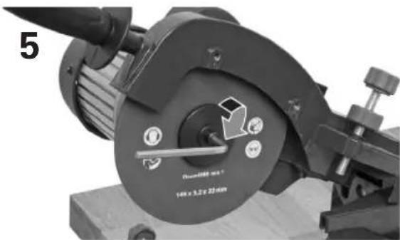
natural_image
Close-up of a mechanical clamp or vise with a rotary knob and adjustment knob, no visible text or symbols.natural_image
Close-up of a mechanical component with circular features and a central hub, no visible text or symbols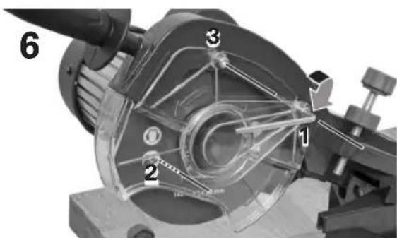
text_image
6 1 2 3text_image
DEPTH GAUGE .030 IN 7/16 .404 3/8 .325 1/4 1/2 7/16 .404 3/8 GRINDING WHEELS FOR CHAINSnatural_image
Close-up of a hand holding a textured rectangular object with a transparent mechanical component above (no visible text or symbols)natural_image
Close-up of a mechanical device with circular components and a central knob, no visible text or symbols.natural_image
Close-up of a mechanical device with a circular component and directional arrows indicating motion (no readable text or symbols)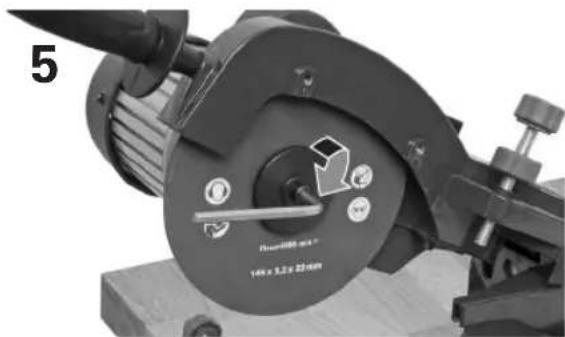
natural_image
Close-up of a mechanical device with a central knob and adjustment knob, labeled 'Round 1000 mm' (no readable text beyond labels)natural_image
Close-up of a mechanical device with circular components and a central dial, no visible text or symbols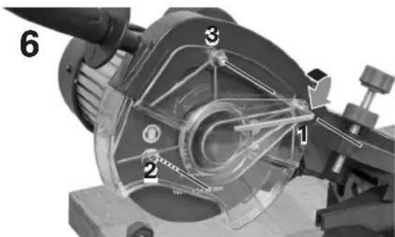
text_image
6 1 2 3text_image
DEPTH GUAGE .025 IN 3/8 1/4 3/8 3/25 3/4 3/8 3/25text_image
DEPTH GAUGE .030 IN 7/16 .404 3/8 .325 1/4 1/2 7/16 .404 3/8 GRINDING WHEELS FOR CHAINSnatural_image
Close-up of a hand holding a textured rectangular object with a transparent mechanical component above (no visible text or symbols)natural_image
Close-up of a mechanical device with a central circular component and adjustment knobs (no visible text or symbols)natural_image
Close-up of a mechanical clamp or fixture with a circular dial and adjustment knob, no visible text or symbols.natural_image
Close-up of a mechanical clamp or tool component with no visible text or symbols on the main body.natural_image
Close-up of a mechanical device with circular components and a central dial, no visible text or symbolsWe are convinced that this machine will exceed your expectations and wish you joy while using it.
Please read this user manual completely and observe the safety instructions.
Scope of delivery
1x Machine base
1x Machine head
1x Handle
1x Trimming stone,
4 mm / 5 mm allen wrench
1x Cutting angle screw kit
1x Table mount screw kit
1x Indicator
If any parts are missing or damaged, please contact your Hornbach Store.
Table of content
Scope of Delivery 129
Symbols 129
Safety Instructions 130
Saw chain parameters 134
Machine preparation 135
Product Overview 136
Intended Use 136
Using the machine 136
Grinding wheel replacement 138
Care & Maintenance 139
Troubleshooting 140
Technical Data 141
Noise 141
Declaration of conformity 142
Disposal 143
Symbols

Please read this user manual carefully and keep it for further reference.

Warning of accident and injury to persons and serious damage to property.

Wear safety glasses for protection of your eyes.

Wear hearing protection for protection of your ears.

Wear dust mask for protection of your respiratory tract.

Wear protective gloves for protection of your hands.

Safety Instructions
GENERAL POWER TOOL SAFETY WARNINGS
WARNING! When using electric tools basic safety precautions should always be followed to reduce the risk of fire, electric shock and personal injury including the following.
Read all these instructions before attempting to operate this product and safe these instructions.
Safe operation
-Keep work area clear.
-Cluttered work areas and benches invite injuries.
Consider work area environment
-Do not expose tools to rain.
- Do not use tools in damp or wet locations.
-Keep work area well lit.
-Do not use tools in the presence of flammable liquids or gases.
Guard against electric shock
-Avoid body contact with earthed or grounded surfaces (e.g. pipes, radiators, ranges, refrigerators).
Keep other persons away
- Do not let persons, especially children, not involved in the work touch the tool or the extension cord and keep them way from the work area.
Store idle tools
-When not in use, tools should be stored in a dry locked-up place, out of the reach of children.
Do not force the tool
-It will do the job better and safer at the rate for which it was intended.
Use the right tool
-Do not force small tools to do the job of a heavy duty tool.
-Do not use tools for purposes not intended; for example do not use circular saws to cut free limbs or logs.
Dress properly
-Do not wear loos clothing or jewellery, they can be caught in moving parts.
-Non skid footwear is recommended when working outdoors
-Wear protective hair covering to contain long hair.
Use protective equipment
-Use safety glasses.
-Use face or dust mask if working operations create dust.
Connect dust extraction equipment
- If the tool is provided for the connection of dust extraction and collection equipment, ensure these are connected and properly used.
Do not abuse the cord
- Never yank the cord to disconnect it from the socket. Keep the cord away from heat, oil and sharp edges.
Secure work
-When possible use clamps or a vice to hold the work. It is safer than using your hand.
Do not overreach
-Keep proper tooting and balance at all times.
Maintain tools with care
-Keep cutting tools sharp and clean for better and safer performance.
-Follow instruction for lubricating an cleaning accessories.
-Inspect tool cords periodically and
if damaged have them repaired by an authorized service facility.
-Inspect extension cords periodically and replace if damaged.
-Keep handles dry, clean and free from oil and grease.
Disconnect tools
-When not in use, before servicing and when cleaning accessories such as blades, bits and cutters, disconnect tools from the power supply.
Remove adjusting keys and wrenches
-Form the habit of checking to see that keys and adjusting wrenches are removed from the tool before turning it on.
Avoid unintentional starting
-Ensure switch is in „off“ position when plugging in.
Use outdoor extension leads
-When the tool is used outdoors, use only extension cords intended for outdoor use and so marked.
Stay alert
-Watch what your are doing, use common sense and do not operate the tool when you are tired.
Check damaged parts
-Before further use of tool, it should be carefully checked to determine that it will operate properly and perform its intended function.
-Check for alignment of moving parts, binding of moving parts, breakage of parts, mounting and any other conditions that may affect its operation.
- A guard or other part that is damaged should be properly repaired or replaced by an authorized service centre unless otherwise indi-
cated in this instruction manual.
-Have defective switches replaced by an authorized service centre.
-Do not use the tool if the switch does not turn it on and off.
Warning
- The use of any accessory or attachment other than one recommended in this instruction manual may present a risk a personal injury.
Have your tool repaired by a qualified person
-The electric tool complies with the relevant safety rules. Repairs should only be carried out by qualified persons using original spare parts, otherwise this may result in considerable danger to the user.
SAFETY WARNINGS FOR CHAIN SHARPENERS
a) Make sure the speed indicated on the grinding wheel is the same or faster, than the rated speed of the tool.
b) Make sure that the dimensions of the grinding wheel are identical to the rated dimensions of the tool.
c) Grinding wheels must always be installed, used and stored according to the instructions of the manufacturer.
d) Always check the grinding wheel before use. Never use damaged, cracked or aged grinding wheels.
e) Make sure to use the backing layers if they are provided with the grinding wheel.
f) Make sure the grinding wheel is installed according to the instructions.
g) Before using the tool, let the wheel run idle for approx. 30 sec. Stop the tool immediately if the tool vibrates heavily or other faults become apparent.
h) Do not use separate reducer
sleeves or adapters to make grinding wheels with larger holes fit properly.
i) Ensure that the tool is securely fastened to a workbench.
j) Take care that the sparks generated during use do not cause any danger, e.g. by hitting persons or igniting inflammable material.
k) The tool runs on after it has been switched off. Wait for the complete stop of the grinding wheel before leaving the tool.
I) Disconnect tool from mains supply. Switch off and wait for the tool to come to a complete standstill before leaving it unattended. Unplug the tool when not in use, before servicing or changing accessories.
m) Always use proper accessories and attachments with this tool. The use of any accessory or attachment or performance of any operation with this tool, other than those recommended in this instruction manual may present a risk of personal injury.
n) Check for damaged parts. Before using the tool, carefully check it for damage to ensure that it will operate properly and perform its intended function. Check for misalignment and seizure of moving parts, breakage of parts and any other conditions that may affect its operation. Have damaged guards or other defective parts repaired or replaced as instructed.
o) Never transport or run the tool without all guards in place and in perfect working condition. Guards ensure that the tool can be operated in its most safe condition.
p) Keep your hands well clear off the grinding wheel. The grinding wheel is sharp. Coming in contact with it may cause serious injury.
q) Always use the chain clamp. A se-
cured chain prevents slipping and provides better results.
RESIDUAL RISKS
In spite of the application of the relevant safety regulations and the implementation of safety devices, certain residual risks cannot be avoided. These are:
- Impairment of hearing if not wearing hearing protection.
- Risk of accidents caused by the uncovered parts of the rotating grinding wheel.
- Risk of thrown parts from damaged grinding wheels.
- Risk of thrown workpieces and parts of the workpiece.
- Health hazards caused by breathing in dusts developed during work.
ADDITIONAL SAFETY INSTRUCTIONS ON RISKS DUE TO VIBRATION
a) The declared vibration data represents the main applications of the appliance, but different uses of the appliance or poor maintenance can result in different vibration data. This may significantly increase the vibration level over the total working period.
b) Additional safety measure shall be taken to protect the user from effects of vibration. Maintain the appliance and its accessories, keep hands warm and organize work patterns and periods.
text_image
EN 133Saw chain parameters
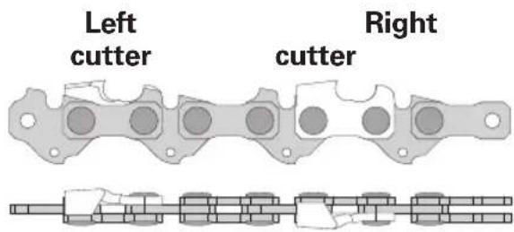
A saw chain is made of repeating segments. A complete segment is shown below, it consists of a left cutter followed by a link and a right cutter followed by a link. Each cutter or link is linked to a guiding element, that keeps the chain on the blade:
text_image
Left cutter Right cutter▶ Rotation direction ▶
Each cutter consists of a cutting angle A and a top plate angle B. Both of these angles can be set on the chain sharpener. The depth gauge C is filed by hand.
Left cutter
| A |  | Cutting angleCutting angle |
| B |  | Top plate angleVise angle |
| C |  | Depth gaugeFiled by hand |
Right cutter
| A |  | Cutting angleCutting angle |
| B |  | Top plate angleVise angle |
| C |  | Depth gaugeFiled by hand |
Check the user manual of your chain saw or saw chain in order to figure out the correct grinding angles.
For most chains, the cutting angle A (set on the cutting angle scale 14) should be between 50°-60° and the top plate angle B (set on the vise angle scale 9), should be between 30°-35°.
Depth gauge
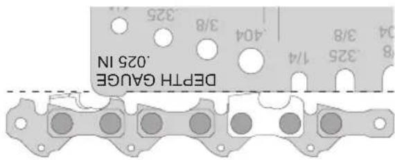
After the cutters have been sharpened, ensure that the depth gauge is respected. The depth gauge has to be lower than the cutters. Check the depth gauge of your chain in the saw chain specifications. If necessary, file the depth gauge using a file with file guide (not included).
For most chains, the depth gauge C is 0.025" - 0.050" or 0.64 mm - 1.28 mm.
Use the indicator to check the depth gauge:
text_image
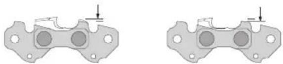
DEPTH GUAGE .025 IN 8 3/8 1/4 404 3/8 325 304The saw chain is worn out and cannot be resharpened if the depth gauge C is at the same level as the indicator on the guiding element:
Sharpable NOT sharpable
natural_image
Two identical mechanical flange components with bolt holes and central bore holes, shown without any text or symbols.Machine preparation
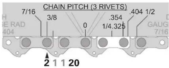
To identify the type of saw chain, place the indicator with its 0 marking centric above a rivet of the saw chain. The type of chain can be read on the index marking either two rivets to the left or right:
text_image
CHAIN PITCH (3 RIVETS) 7/16 3/8 0 .354 1/4.325 .404 1/2 HA SE RAD 404 GAUG 7/16 2 1 1 20The example above matches the left marker and indicates a 3/8" chain.
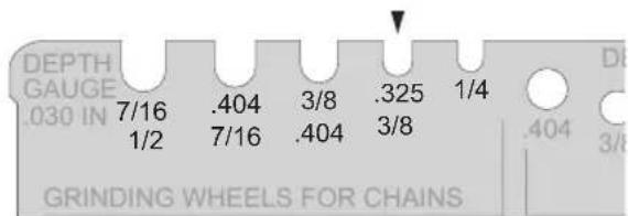
The indicator also shows the corresponding grinding wheel thickness:
text_image
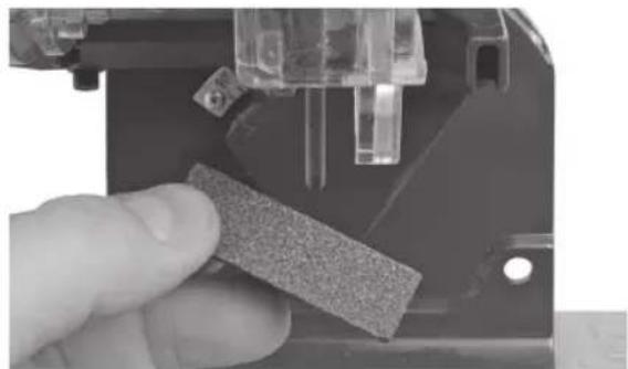
DEPTH GAUGE .030 IN 7/16 .404 3/8 .325 1/4 1/2 7/16 .404 3/8 GRINDING WHEELS FOR CHAINSCheck if the proper grinding wheel is installed. If necessary, use the trimming stone to give the grinding wheel the smooth round shape of the indicator.
natural_image
Close-up of a hand inserting a textured rectangular object into a mechanical component (no visible text or symbols)If an other grinding wheel needs to be installed, follow the instructions given in 'Grinding wheel replacement'.
Product overview
1 Motor
2 Machine head
3 Handle
4 Guard
5 Chain stopper screw
6 Chain stopper
7 Vise
8 Chain lock lever
9 Vise angle scale
10 Vise lock knob
11 ON/OFF switch
12 Cutting depth screw
13 Cutting angle lock knob
14 Cutting angle scale
15 Grinding wheel
16 Machine base
17 Table mount
18 Chain bar
Intended Use
The machine is intended for sharpening chainsaw chains specified in technical data.
Any other use or modification to the machine is considered as improper use and could cause considerable dangers.
The appliance is not intended for commercial use.
Using the machine

Caution! Make sure the grinding wheel has a smooth d shape.
- Take the steps S1-S8.
- Raise the machine head 2.
- Press the green I (on) button 11 to switch the machine on.
- Wait until the grinding wheel has reached full speed.
- Slowly lower the machine head 2 and sharpen the first right cutter.
- Raise the machine head 2.
- Loosen the chain lock lever 8 and pull the chain until the next right cutter appears (every two cutters).
- Pull the chain to the left against the chain stopper 6 and tighten the chain lock lever 8. Slowly lower the machine head 2 and sharpen the remaining right cutters with this adjustment.
- Once all right cutters are sharpened, press the red O (off) button 11 to switch the machine off.
- To sharpen the left cutters, take the steps S3-S8, but set the top plate angle B on the vise in the opposite direction.
- Take the steps 2.-9. from these instructions in order to sharpen the left cutters.
1 Installation Install the machine base 16 to a level and stable work surface, using the table mount screw kit: M8x100 screws, washers and nuts.
2 Install the machine head 2 to the machine base 16 using the cutting angle screw kit: M8x50 screw, washer and cutting angle lock knob.
S1
Raise chain stopper
se the chain stopper 6 of the machine vise 7.

Caution! Make sure the appliance is switched off and un-ged.
Set top plate angle / B
Loosen the vise lock knob 10 and set the desired top plate angle at the vise angle scale 9. Tighten the vise lock knob 10.
Set cutting angle / A
Loosen the cutting angle lock knob 13 and set the desired cutting angle at the cutting angle scale 14. Tighten the cutting angle lock knob 13.
S49
Insert chain
Insert the saw chain into the chain bar 18. The rotation direction is from left to right.

Caution! The saw chain is sharp, make sure to wear active gloves.
S5
Lower chain stopper
Lower the chain stopper 6 and pull the saw chain to the right until a right cutter is centric on the vise 7. Pull the saw chain to the left until the cutter engages at the chain stopper 6.
S6
Lower grinding wheel
Carefully lower the grinding wheel 15 behind a right cutter. Use the chain stopper screw 5 to set the required distance between cutter and grinding wheel 15.
S7
Lock chain
If the proper distance is set on the chain stopper screw 5 lock it with the counter nut. Tighten the chain lock lever 8 to lock the chain in place.
S8
Set cutting depth
With the grinding wheel still lowered, set the required cutting depth on the cutting depth screw 12 and lock it with the counter nut.
3
Install the handle to the machine head 2.
4
Plug the supply cord to a suitable wall outlet.
Grinding wheel replacement

Warning! Make sure the machine is switched off and unplugged.
text_image
1 2 3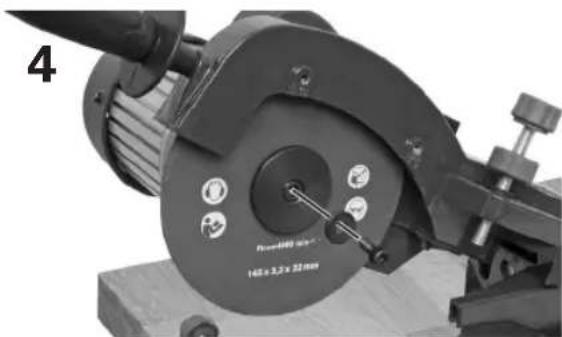
natural_image
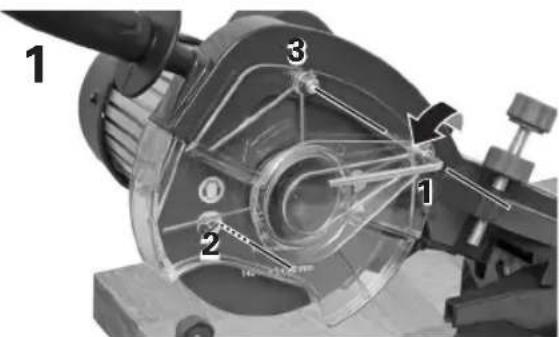
Close-up of a mechanical device with circular components and a central knob, no visible text or symbols.Use the 4 mm allen wrench to remove the three screws holding the guard and remove the guard downwards.
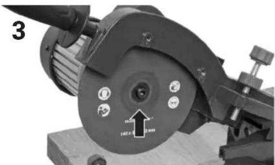
Reinstall the wheel flange with its washer and bolt.
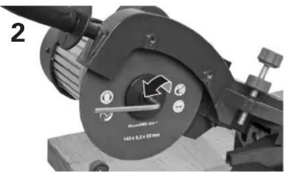
natural_image
Close-up of a mechanical device with a circular component and directional arrows indicating motion (no readable text or symbols)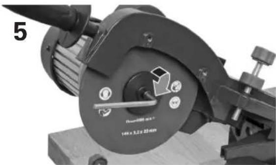
natural_image
Close-up of a mechanical device with a rotary knob and adjustment knob, no visible text or symbolsUse the 5 mm allen wrench to remove the screw holding the grinding wheel and remove the grinding wheel downwards.
Use the 5 mm allen wrench to tighten the screw holding the grinding wheel.
natural_image
Close-up of a mechanical device with circular components and a central dial, no visible text or symbols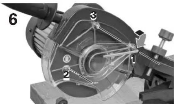
text_image
6 1 2 3Place a new grinding wheel on the spindle of the chain sharpener.
Use the 4 mm allen wrench to reinstall the guard at its three mounting positions.
Care & Maintenance

Warning! Make sure the machine is switched off and un-ged.
- Always keep the machine clean, dry and free of oil or grease.
- Wear safety glasses and gloves to protect your eyes and hands whilst cleaning.
- For safe and proper working, always keep the machine and ventilation slots clean.
- Regularly check for obvious defects and/or damaged components.
- Periodically check all fixings. These could become loose with time due to vibration.
- The most used part is the grinding wheel. Inspect the grinding wheel regularly. If the grinding wheel is worn or blunt, it must be replaced immediately.
- Replace any worn or damaged parts.
- If the body of the machine needs cleaning, wipe it with a brush or a soft damp cloth. A mild detergent can be used but nothing like alcohol, petrol or other cleaning agent.
- Never use caustic agents to clean plastic parts.
- Lubricate all moving parts at regular intervals.
- Store the machine in a dry place and out of the reach of children.

Danger! If the supply cord is damaged, it must be re-d by the manufacturer or its ce agent or similarly qualified on in order to avoid hazard.
Troubleshooting

Warning! Make sure the appliance is switched off and unplugged. Always wear protective gloves.
Problem Possible cause Solution
| Motor does not run | The machine is not properly plugged into the mains | Properly plug the machine to a suitable wall socket |
| Power turned off Turn power on | ||
| Strong vibration of the machine | The sharpener is not properly installed | Properly install the sharpener to a level and stable surface |
| The arm is not properly installed to the machine base | Properly install the arm to the machine base | |
| The vise is not properly installed to the machine base | Properly install the vise to the machine base | |
| The grinding wheel is not properly installed | Properly install the grinding wheel | |
Technical Data
Type FQ-SKS235
| Nominal voltage 230 V~ / 50 Hz | |
| Rated power S1: 235 W | |
| No-load speed n0 | 3000/min |
| Grinding wheel arbour ø 22 mm | |
| Grinding wheel outer ø max. 145 mm | |
| Grinding wheel thickness 3.2 mm | |
| Top blade angle adjustment + 40° to - 40° | |
| Cutting angle adjustment 90° to 40° | |
| Sharpenable chain types 1/4" - 0.325" - 3/8" - 0.404" - 3/4" | |
| Protection Class I | |
| Net weight 5.8 kg | |
| Sound pressure level LpA | 68.3 dB(A) / Uncertainty K = 3 dB(A) |
| Sound power level LWA | 81.3 dB(A) / Uncertainty K = 3 dB(A) |
| Max. vibration emission (ah) | 3,05 m/s2Uncertainty K = 1.5 m/s2 |
The values given are valid for nominal voltages U of 230 V. For lower voltage and models for specific countries, these values may vary.
Please observe the article number on the type plate of the machine. The trade names of the individual machine may vary.
Vibration
The declared vibration total value has been measured in accordance with a standard test method and may be used for comparing one tool with another.
The declared vibration total value may also be used in a preliminary assessment of exposure.

Warning! The vibration emission during actual use can
differ from the declared total value depending on the use of the tool.
Declaration of Conformity
CE We declare, that the product described in Technical Data:

Chain Sharpener 235 W FQ-SKS 235
manufactured for:
Hornbach Baumarkt AG Hornbachstraße 11 76879 Bornheim / Germany
is in conformity with the following directives:
Machinery Directive 2006/42/EC RoHS Directive 2011/65/EC EMC Directive 2014/30/EU
and in accordance to the following applicable harmonized standards:
EN 61029-1:2009+A11 EN 61029-2-10:2010 EN 55014-1:2006+A1+A2 EN 55014-2:1997+A1+A2 EN 61000-3-2:2014 EN 61000-3-3:2014
The conformity with the Noise Emission of Outdoor Equipment Directive is verified by the conformity assessment procedure according to annex VI, and the Directive 2005/88/EC.
Measured sound power level: 81.3 dB(A)
A. Indiana Fale
Andreas Back Head of Quality Management, environment & CSR Person authorised to compile the technical file
The crossed-out wheeled bin logo requires the separate collection of waste electric and electronic equipment (WEEE).
Such equipment may contain dangerous and hazardous substances. These machines must be returned to a designated collection point for the recycling of WEEE and must not be disposed as unsorted municipal waste. By doing so, you will help to conserve resources and protect the environment. Contact your local authorities for more information.
Children must not play with plastic bags and packaging material, due to possible injury or danger of suffocation. Store such material safely or dispose of environmentally friendly.